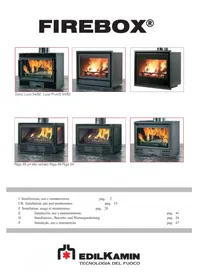
FIREBOX - Fireplace EDILKAMIN - Free user manual and instructions
Find the device manual for free FIREBOX EDILKAMIN in PDF.


| Product type | Closed fireplace |
| Brand | Edilkamin |
| Model | FIREBOX (DECO, RIGA, LUCE, LUCE PLUS ranges) |
| Rated power | 9 to 12 kW depending on model |
| Fuel | Wood logs (moisture < 20%) |
| Optimal hourly consumption | 2.5 to 3.6 kg/h depending on model |
| Weight with packaging | 111 to 144 kg depending on model |
| Flue diameter | 160 or 200 mm (depending on height) |
| External air intake section | 80 cm² |
| Hot air outlets | 2 x Ø 140 mm |
| Ventilation | Natural or forced (2 fans 160 m³/h each) |
| Heated volume | 235 to 315 m³ depending on insulation |
| Electrical supply | 230 V (for ventilated version) |
| Firebox material | Cast iron and vermiculite |
| Structure | Steel 30/10 |
| Glass | Ceramic resistant to 800 °C |
| Door | Automatic closing (except models with glass side) |
| Post-combustion system | Yes (except models with glass side) |
| Safety | Overheat thermostat, safety distance 80 cm, protective gloves |
| Maintenance | Annual sweeping, glass cleaning with specific product (Glasskamin) |
| Spare parts | Available from authorized dealer |
| Accessories | Hot air duct kits (1, 2 or 3 parts) |
Frequently Asked Questions - FIREBOX EDILKAMIN
User questions about FIREBOX EDILKAMIN
0 question about this device. Answer the ones you know or ask your own.
Ask a new question about this device
Download the instructions for your Fireplace in PDF format for free! Find your manual FIREBOX - EDILKAMIN and take your electronic device back in hand. On this page are published all the documents necessary for the use of your device. FIREBOX by EDILKAMIN.
USER MANUAL FIREBOX EDILKAMIN
natural_image
Exterior view of a modern industrial stove with visible flames and cooling fins (no text or symbols)Deco Luce 54/62 Luce Plus/S 54/62
natural_image
Exterior view of a modern fire extinguisher with visible flames and wood shavings (no text or symbols)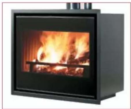
natural_image
Exterior view of a black industrial stove with visible flames and wood shavings (no text or symbols)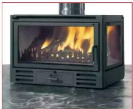
natural_image
Exterior view of a black portable stove with visible flames and smoke (no text or symbols)Riga 49 un lato vetrato Riga 49 Riga 54
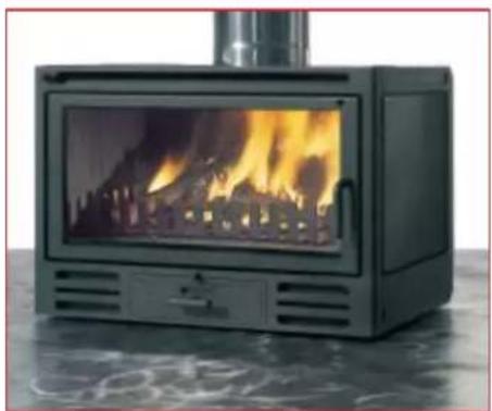
natural_image
Exterior view of a black portable stove with visible flames and smoke, placed on a reflective surface (no text or symbols)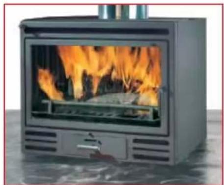
natural_image
Exterior view of a modern outdoor stove with visible flames and a lid (no text or symbols)UK Installation, use and maintenance
F Installation, usage et maintenance
natural_image
Exterior view of a modern industrial stove with visible flames and smoke (no text or symbols)natural_image
Exterior view of a black industrial stove burner with visible flames and wood shavings (no text or symbols)natural_image
Close-up of a metallic vehicle front panel with a circular emblem and a star symbol (no readable text or numbers)natural_image
Exterior view of a black industrial stove with visible flames and wood shavings (no text or symbols)natural_image
Close-up of a metallic rectangular device with a circular emblem and a star mark, no visible text or symbols.natural_image
Modern portable stove with visible flames and wood shavings (no text or symbols)natural_image
Modern portable stove with visible flames and wood shavings (no text or symbols)natural_image
Exterior view of a modern black utility stove with visible flames and internal structure (no text or symbols)Riga 49
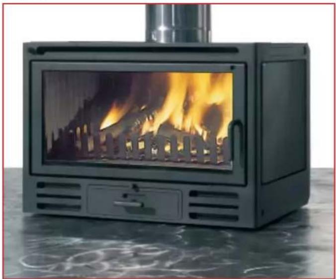
natural_image
Modern black portable stove with visible flames and smoke, placed on a reflective surface (no text or symbols)natural_image
Modern portable stove with visible flames inside, placed on a reflective surface (no text or symbols)natural_image
3D mechanical component diagram showing internal cavity with blue directional arrows and label 'fig. A' (no text or symbols on the object itself)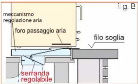
Thank you for purchasing an Edilkamin Firebox®.
The Edilkamin Firebox ^® is made from the finest materials using the most cutting-edge technologies.
For optimal use and to maximise advantages and comfort, please read the operating instructions carefully.
We wish you many happy, relaxing hours next to your new Firebox®. Please contact our specialized dealer where you purchased your Firebox® for anything you may require, detailing the warranty number and the type of the device.
General note Protections
Firebox ^® can work with the door open when it is installed with an external air intake of at least 200 cm ^2 .
If the external air intake has a smaller section the door must always be fully closed.
When operating with the door open, Firebox ^® must be constantly monitored to avoid fire hazards, due to the escape of sparks and embers.
During combustion, never leave the door and/or ash tray slightly open because this will cause a violent flame that will damage Firebox ^® and its covering.
Edilkamin will only be liable for the proper functioning of the Firebox ^® when operated according to the instructions in this manual and the product sheet attached to the product.
Edilkamin will not be liable if third parties modify or tamper with the product.
uel
Fire protection outside the range of the heat from the fireplace
Infl ammable objects (such as wooden shelves) must be kept at least 5 cm away from Firebox®.
Fire protection inside the range of the heat from the fireplace
Do not place infl ammable objects (such as furniture, rugs, fl owners, etc.) within a radius of 80 cm in front and to the sides of Firebox ^® .
Protection from burns
During operation the surfaces and handles of Firebox ^® become hot.
For any operation, always use the protective gloves provided.
Only enter the 80 cm radius to load fuel; spending a prolonged period in this area could lead to burns.
Keep children away from Firebox ^® .
Firebox ^® is built to burn logs.
Maximum efficiency is achieved with the mouth of the fireplace closed.
The wood must always burn with a flame, avoid a smouldering fire.
Do not exceed the hourly consumption of wood shown in the technical sheet provided. Using a greater amount of wood could damage Firebox ^® .
It is preferable not to burn an hour's worth of wood in a single load.
Burn only dry wood (maximum 20% moisture), without chemicals or plastic wrappers.
Dry branches, paper and wood chips can only be used for ignition.
Recommended wood types
(in descending order)
1 kg of dry wood (20% moisture equal to about two years of seasoning) generates 3500/3700 kcal/h
so, burning moist wood means obtaining less heat
Moreover, moist wood causes a smouldering fire with increased formation of tar and condensate, resulting in damage to the chimney.
In any case, the fi replace will be dirtier.
Burning of waste, especially plastic, packaging and painted or treated wood, will damage the chimney pot and generate harmful emissions.
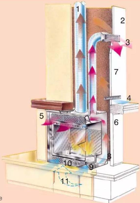
1 fl ue
2 mantel
3 hot-air outlet
4 air-intake slots for mantel ventilation
5 wooden beam to be protected with a protective screen
6 covering
7 wall insulation
8 Firebox®
9 fans
10 ash tray and grille shaker
11 external air intake
FIREBOX®
Quick installation one-piece fireplace:
- compact
■ square-shaped
■ very easy to cover
■ particularly suitable for insertion in old malfunctioning fi replaces to be renovated
Available in 5 series and 17 versions: with cast-iron front
■ DECO for a rustic decor:
1 model, 1 version
with steel front
■ RIGA 49 series, essential lines: 2 models, 3 versions
■ RIGA 54 series, essential lines: 1 model, 1 version
■ LUCE series, innovative design: 1 model, 4 versions
with glass front
■ LUCE PLUS series with total glass:
1 model, 8 versions
Technical features:
Single-piece, pre-assembled:
consisting of a double 30/10 steel structure that ensures a perfect seal against leaks of smoke between the combustion chamber and the cavity where the hot air circulates.
Cast-iron/vermiculite combustion chamber:
ensures long life.
Post combustion\*:
a system that makes it possible to re-burn combustion residue, reducing emissions and increasing thermal efficiency.
Hot-air ducting:
by means of fl exible aluminium tubes it is possible to duct the hot air produced, to also heat other rooms of the house.
External air-intake mechanism:
allows connection to the external air duct as required by UNI technical standards. It is equipped with a damper and fi tting.
Forced ventilation:
allows faster and more uniform air distribution. It consists of:
- a two-speed switch;
- a thermostat to prevent overheating of the fans;
- two fans housed behind the lower grille.
Very high efficiency and low consumption: the optimal consumption of firewood indicated for each model is sufficient to achieve maximum efficiency and therefore a considerable cost saving, less frequent reloading and a decrease in the space needed for wood storage.
Self-closing door\*:
hermetically seals the combustion chamber and is accompanied by a damper for
the intake of combustion air;
Allows extremely high efficiency to be achieved, and wood consumption to be halved.
Also reduces the need for air intake with consequent decrease in the cross-sectional area of the air-intake duct (80 cm ^2 instead of 200 cm ^2 ).
The door provides secure protection in case of unattended operation.
Glazed side:
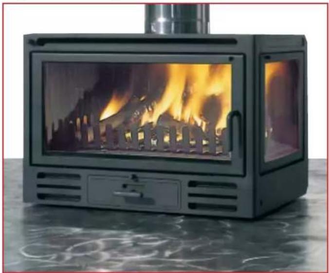
available on the Riga 49 model (both left and right versions) to provide a better view of the fi re.
Glazing:
exclusive use of ceramic glass, which is thermal-shock resistant up to 800°C.
A special air-distribution system greatly reduces soot deposits on the glass.
* not fitted on Riga 49 glazed-side versions
cast-iron front
DECO
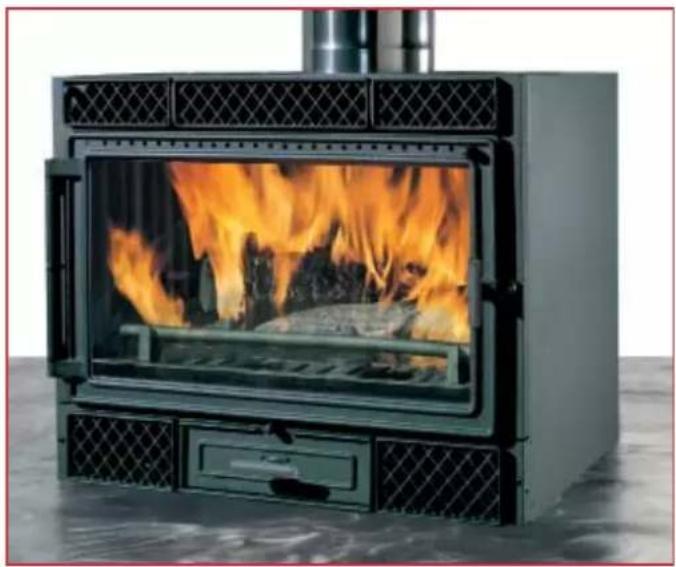
natural_image
Exterior view of a modern industrial stove with visible flames and smoke (no text or symbols)Three kits are available, complete with everything needed to duct the hot air (page 26):
kit one: only the fi replace room
kit two: fireplace room and 1 adjacent rooms
kit three: fireplace room and 2 adjacent rooms
Optional mouth surround frame
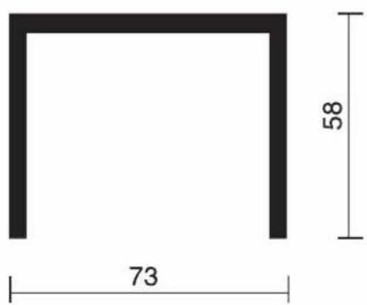
| Technical features: | ||
| Power output kW 9 | ||
| Optimal wood consumption kg/h 2,5 | ||
| Weight including packaging kg 124 | ||
| ∅ stainless steel flue (for minimum height of 2 m) cm 20 | ||
| ∅ stainless steel flue (for minimum height of 4 m) cm 16 | ||
| ∅ hot-air outlet cm 14 x 2 | ||
| External air intake (cross-sectional area) cm | ^2 | 80 |
| Fan flow rate (free flow) m | ^3/h 160 x 2 | |
| Fan power consumption W 20 x 2 | ||
| Heatable volume (insulated according to Italian Law 10/1991) | m^3 | 235 |
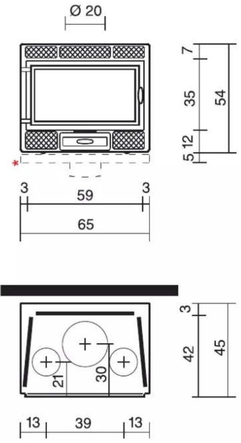
glass front
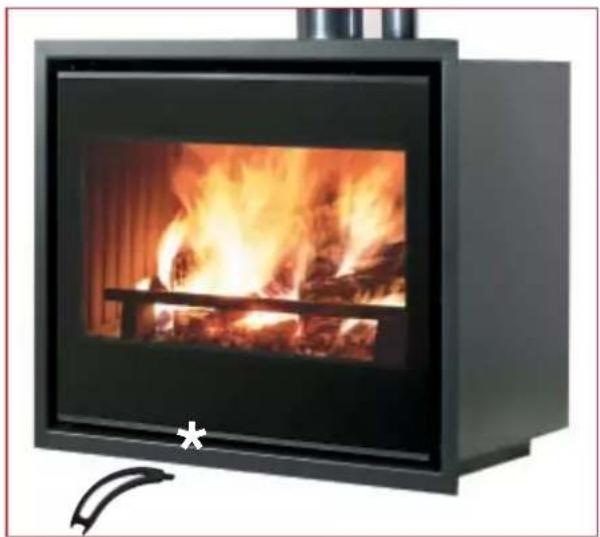
LUCE PLUS/S 62
ENGLISH
natural_image
Exterior view of a black industrial stove with visible flames and wood shavings (no text or symbols)Three kits are available, complete with everything needed to duct the hot air (page 26):
kit one: only the fi replace room
kit two: fi replace room and 1 adjacent rooms
kit three: fireplace room and 2 adjacent rooms
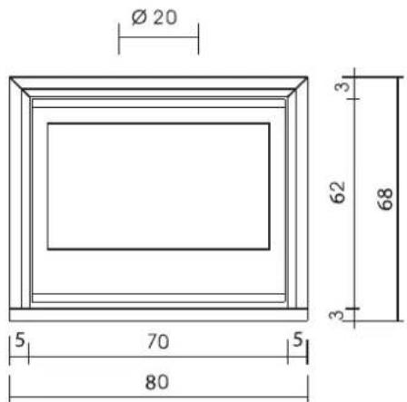
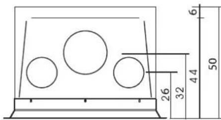

| Technical features: V | ||
| Power output kW 11 | ||
| Optimal wood consumption kg/h 3 | ||
| Weight including packaging kg 137 | ||
| ∅ stainless steel flue (for minimum height of 2 m) cm 20 | ||
| ∅ stainless steel flue (for minimum height of 4 m) cm 16 | ||
| ∅ hot-air outlet cm 14 x 2 | ||
| External air intake (cross-sectional area) cm | ^2 | 80 |
| Fan flow rate (free flow) m | ^3/h 160 x 2 | |
| Fan power consumption W 20 x 2 | ||
| Heatable volume (insulated according to Italian Law 10/1991) | m^3 | 285 |
natural_image
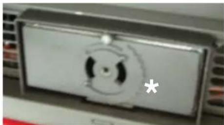
Close-up of a metallic vehicle front panel with a circular emblem and a star symbol (no readable text or numbers)Combustion-air adjustment valve, manoeuvrable with door closed using the "cold hand" handle
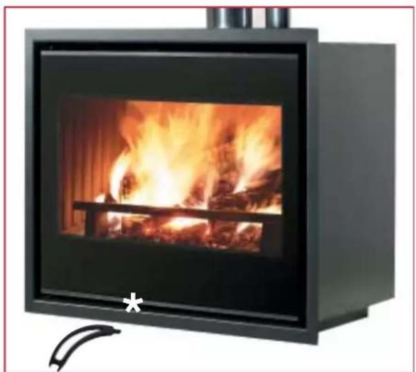
glass front
LUCE PLUS/S 54
natural_image
Modern black industrial stove with visible flames and a wooden frame (no text or symbols)Three kits are available, complete with everything needed to duct the hot air (page 26):
kit one: only the fireplace room
kit two: fireplace room and 1 adjacent rooms
kit three: fireplace room and 2 adjacent rooms
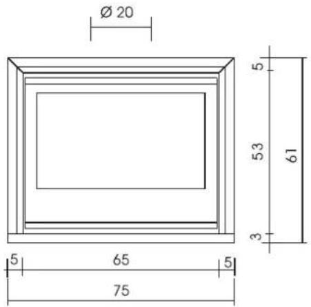
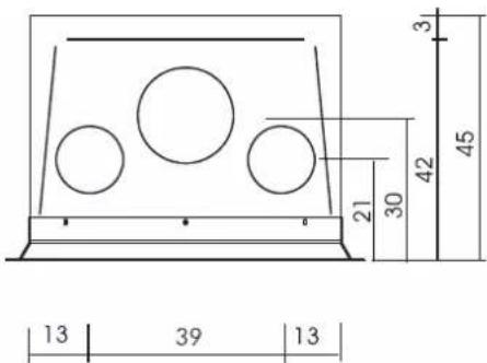
| Technical features: | ||
| Power output kW 9 | ||
| Optimal wood consumption kg/h 2,5 | ||
| Weight including packaging kg 120 | ||
| ∅ stainless steel flue (for minimum height of 2 m) cm 20 | ||
| ∅ stainless steel flue (for minimum height of 4 m) cm 16 | ||
| ∅ hot-air outlet cm 14 x 2 | ||
| External air intake (cross-sectional area) cm | ^2 | 80 |
| Fan flow rate (free flow) m | ^3/h 160 x 2 | |
| Fan power consumption W 20 x 2 | ||
| Heatable volume (insulated according to Italian Law 10/1991) | m^3 | 235 |
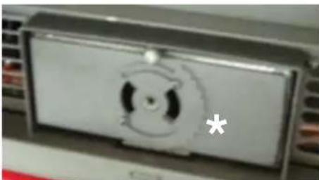
natural_image
Close-up of a metallic electronic device with a circular button and a star symbol (no readable text or labels)Combustion-air adjustment valve, manoeuvrable with door closed using the "cold hand" handle
steel front
LUCE 62
ENGLISH
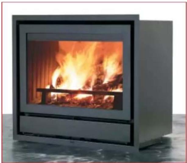
natural_image
Modern portable stove with visible flames and wood shavings (no text or symbols)Three kits are available, complete with everything needed to duct the hot air (page 26):
kit one: only the fi replace room
kit two: fi replace room and 1 adjacent rooms
kit three: fireplace room and 2 adjacent rooms
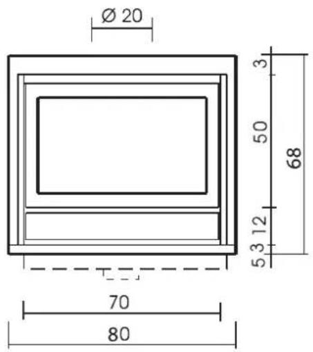
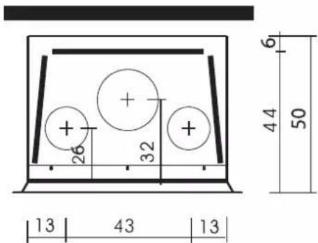
| Technical features: | ||
| Power output kW 11 | ||
| Optimal wood consumption kg/h 3 | ||
| Weight including packaging kg 144 | ||
| ∅ stainless steel flue (for minimum height of 2 m) cm 20 | ||
| ∅ stainless steel flue (for minimum height of 4 m) cm 16 | ||
| ∅ hot-air outlet cm 14 x 2 | ||
| External air intake (cross-sectional area) cm | ^2 | 80 |
| Fan flow rate (free flow) m | ^3/h 160 x 2 | |
| Fan power consumption W 20 x 2 | ||
| Heatable volume (insulated according to Italian Law 10/1991) | m^3 | 285 |
steel front
LUCE 54
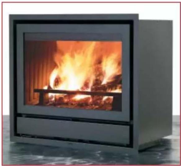
natural_image
Exterior view of a modern fire extinguisher with visible flames and wood inside (no text or symbols)Three kits are available, complete with everything needed to duct the hot air (page 26):
kit one: only the fi replace room
kit two: fi replace room and 1 adjacent rooms
kit three: fireplace room and 2 adjacent rooms
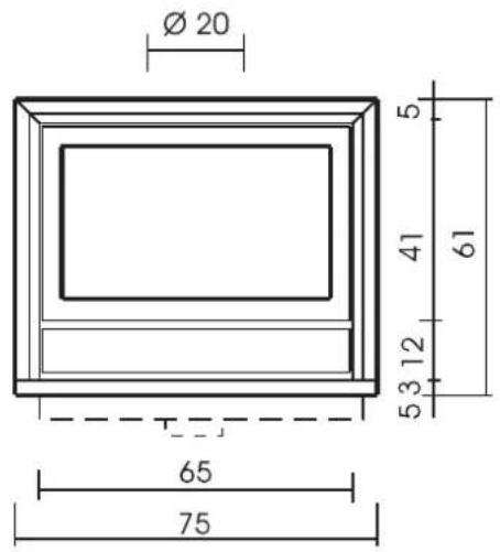
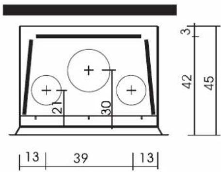
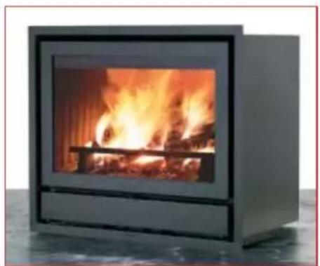
| Technical features: | ||
| Power output kW 9 | ||
| Optimal wood consumption kg/h 2.5 | ||
| Weight including packaging kg 126 | ||
| ∅ stainless steel flue (for minimum height of 2 m) cm 20 | ||
| ∅ stainless steel flue (for minimum height of 4 m) cm 16 | ||
| ∅ hot-air outlet cm 14 x 2 | ||
| External air intake (cross-sectional area) cm | ^2 | 80 |
| Fan flow rate (free flow) m | ^3/h | 160 x 2 |
| Fan power consumption W 20 x 2 | ||
| Heatable volume (insulated according to Italian Law 10/1991) | m^3 | 235 |
steel front
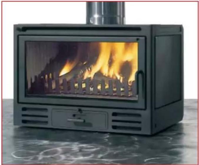
RIGA 49 - RIGA 49/1L
Riga 49 one side glazed
natural_image
Exterior view of a black portable stove with visible flames and metal chimney (no text or symbols)Riga 49
natural_image
Modern black portable stove with visible flames and smoke, placed on a reflective surface (no text or symbols)| Technical features: | ||
| Power output kW 12 | ||
| Optimal wood consumption kg/h 3,6 | ||
| Weight including packaging (RIGA 49 1 L) kg | 122-(119) | |
| ∅ stainless steel flue (for minimum height of 2 m) cm 20 | ||
| ∅ stainless steel flue (for minimum height of 4 m) cm 16 | ||
| ∅ hot-air outlet cm 14 x 2 | ||
| External air intake (cross-sectional area) cm | ^2 | 80 |
| Fan flow rate (free flow) m | ^3/h 160 x 2 | |
| Fan power consumption W 20 x 2 | ||
| Heatable volume (insulated according to Italian Law 10/1991) | m^3 | 315 |
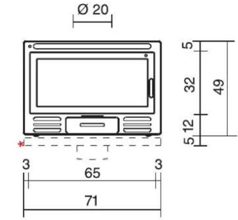
frontale
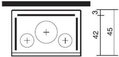
Three kits are available, complete with everything needed to duct the hot air (page 26):
kit one: only the fi replace room
kit two: fi replace room and 1 adjacent rooms
kit three: fi replace room and 2 adjacent rooms
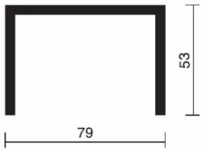
Optional mouth surround frame
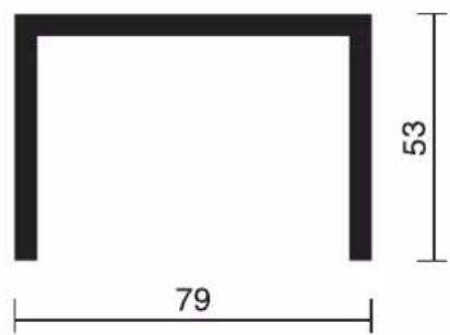
steel front
RIGA 54
natural_image
Modern portable stove with visible flames inside, placed on a tiled floor (no text or symbols)Optional mouth surround frame
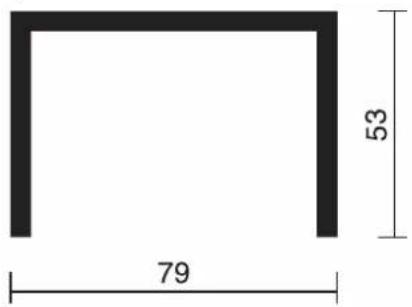
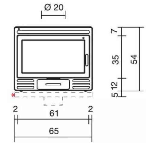
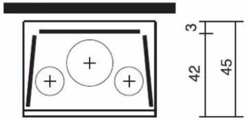
frontale
| Technical features: | ||
| Power output kW 9 | ||
| Optimal wood consumption kg/h 2,5 | ||
| Weight including packaging kg 111 | ||
| ∅ stainless steel flue (for minimum height of 2 m) cm 20 | ||
| ∅ stainless steel flue (for minimum height of 4 m) cm 16 | ||
| ∅ hot-air outlet cm 14 x 2 | ||
| External air intake (cross-sectional area) cm | ^2 | 80 |
| Fan flow rate (free flow) m | ^3/h | 160 x 2 |
| Fan power consumption W 20 x 2 | ||
| Heatable volume (insulated according to Italian Law 10/1991) | m^3 | 235 |
Three kits are available, complete with everything needed to duct the hot air (page 26):
kit one: only the fi replace room
kit two: fi replace room and 1 adjacent rooms
kit three: fi replace room and 2 adjacent rooms
WARNINGS
Installing Firebox®
Besides the contents of this document, please take into consideration the UNI standards:
- no. 10683 - Wood-Burning Heating Appliances: Installation Requirements.
- no. 9615/90 - calculation of the inner dimensions of fi replaces.
Specifically:
- before starting any installation operation, it is important to check the compatibility of the system as established by the UNI 10683 standard.
- after installation, the installer must "start-up" the system and issue the documentation required by the UNI 10683 standard.
Using Firebox®
Smoke damper adjustment: in the event of diffi culty clearing the smoke (low draught) evacuation can be improved by adjusting the screw on the damper control rod. By turning the screw (clockwise) and closing the door, the damper will remain slightly inclined, helping the smoke to flow out.
Ash tray: during operation, it must always be completely closed; otherwise a "forge effect" is created with consequent damage to the Firebox® structure and covering components.
Efficiency and fuel consumption: to obtain the declared efficiency, it is necessary to burn 3.5 - 4 kg/h of wood (depending on the model as shown in the technical specification table); use with an excessive amount of wood may cause damage.
When Firebox ^® is running at full power, it generates a signifi cant amount of heat. Therefore, during installation, carefully check that there are no areas of contact with wood or other combustible materials and that any such materials are out of range of the heat which radiates from the fi replace.
There should be insulation between Firebox® and these materials or a gap of at least 3 cm with free air flow, to prevent excessive heat build-up.
Special front protection panels are available for beams on request.
Electrical connections (for forced ventilation versions)
- These must conform to professional installation and construction standards.
- The electrical components are always live; before any maintenance, disconnect the plug and turn off the electrical panel of the dwelling.
- Avoid contact between electrical wires, Firebox ^® and the flue.
- The electrical equipment supplied with Firebox ^® must not be tampered with in any way.
For further details, con- sult the following document:
"Firebox® Instructions for use" attached to the product.
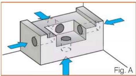
EXTERNAL AIR INTAKE (Figs. A-B)
The connection with the outside, made with a cross-sectional area of at least 80/200 cm ^2 (depending on the model) is absolutely essential, as prescribed by the standard governing installation requirements (UNI 10683). It must, therefore, be provided.
It is made with a duct that must bring outside air directly to the adjustment mechanism (Fig. B). The regulation mechanism must be attached to the bottom of Firebox ^® .
During installation, carefully seal the points where the external air may leak.
The external air duct may come from behind, from below, from the side, or consist of a fl ex-ible hose which runs directly from the outside to the mechanism vent (Fig. B).
It is advisable to apply a protection grille on the outside of the air-intake duct that does not, reduce the air-flow capacity.
The external air must be drawn in at floor level.
If it is not possible to do as described above, place the external air intake as near to Firebox® as possible.
natural_image
3D mechanical component diagram showing internal cavity and flow direction arrows (no text or symbols)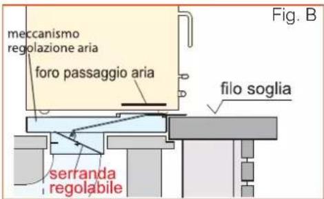
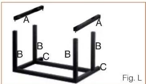
Screw the 2 frame-fastening brackets (A) to the bottom of the Firebox® structure, using the ø 3.6 holes and the six 4.8x13 screws provided.
At the pre-cuts, cut the vertical tubes of the support frame (B) to the desired height for positioning Firebox ^® .
Using the pins provided, fi t the frame (B) to the brackets (A) previously fastened to Firebox®.
Take care that the horizontal projections (C) of the frame are on the rear facing the wall.
Lock the support stand with the four 8x40 screws provided.
Position Firebox ^® with stand and fasten to the floor using the anchors and 8x70 screws provided.
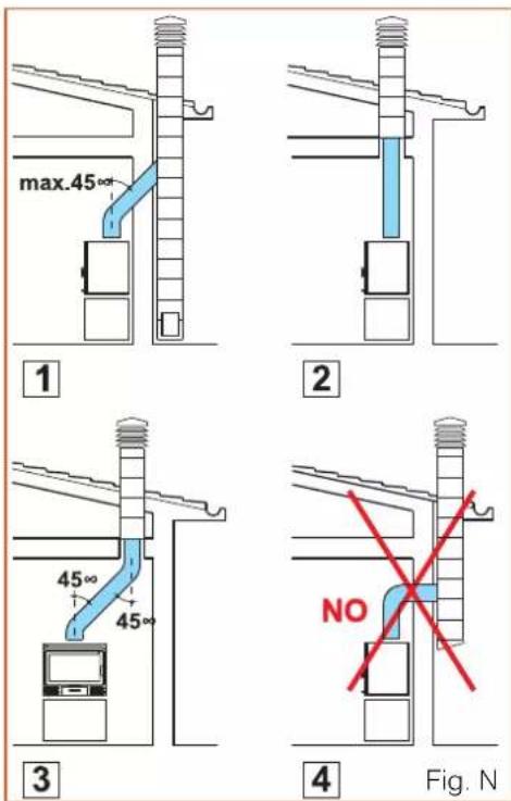
FLUES (Fig. N)
The Firebox® smoke outlet has a circular cross-section. It is provided to allow the use with EdilKamin stainless steel pipes (rigid single-wall or insulated rigid double-wall), that allow a quick, secure connection to the flue.
If the fl ue inlet is not vertical in relation to the fireplace, the connection between the fireplace and fl ue must not narrow or slope by more than 45° (1-3).
In the case of old or oversized fl ues, it is advisable to line them with stainless steel pipes of a suitable diameter and with suitable insulation. For fl ues located outside, we recommend using the stainless In the case of outdoor fl ues, it is advisable to use insulated double-wall stainless steel pipes.
The constructional features, in particular as regards mechanical strength, insulation and gas-tightness, must be able to withstand a smoke temperature of at least 450 °C.
Use high temperature mastic to seal where the steel pipe connects to the Firebox® smoke outlet.
Using the rigid, stainless steel fl ue requires a female-female fi tting on the smoke outlet of the fi replace.
The chimney pot should be placed in full wind.
INSTALLATION IN AN EXISTING FIREPLACE FITTED WITH EXTERNAL AIR INTAKE
(when part numbers are not specified, refer to the specification tables on the previous pages)
N.B.: if you do not want to alter the existing hood, the installation must be carried out without hot-air ducting (leaving the upper outlets closed). In this case, the hot air only enters the room through the slots on the front, above the door.
a) make a pit (Fig. A), in the basement of the existing fi replace, big enough to hold the external air intake mechanism (Fig. B)
b) this pit must communicate with an external air inlet duct through a passage with cross-sectional area of at least 80-200 cm² (depending on the model)
c) position the mechanism (Fig. B) flush with the upper face of the floor, carefully sealing the points where outside air may leak
d) make sure the damper moves correctly (Fig. B)
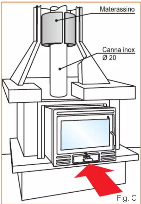
e) with a hose clamp ∅ 16-20 cm fit a length of at least 2 meters of stainless steel fl ue, with the fitting for a ∅ 16 cm flue or the fitting for a ∅ 20 cm fl ue (Fig. C)
f) wrap the section of steel pipe with a multi-layered ceramic fi bre mat or equivalent material (Fig. C)
g) slip the section into the flue of the existing fi replace and make sure the thickness of the ceramic fibre wrapping is sufficient to completely fi ll the space between the new steel pipe and the existing fl ue (Fig. C)
h) place Firebox ^® onto the mechanism (Fig. B) checking that:
- the lower fl ange has been removed to allow the flow of external air;
- The deflector is open, using the knob located at the top left on the front of Firebox®;
- a seam of high temperature mastic has been inserted where the flue attaches and on the smoke outlet collar;
i) lower the previously inserted stainless steel pipe until it fi ts into the Firebox® smoke outlet collar.
Do this by hand in the space between Firebox ^® and the top of the inlet to the existing chimney
I) if Firebox® is ventilated, leave a space for the fan power cord making sure it does not come into contact with hot parts
m) carefully close off the remaining space between Firebox® and the edges of the inlet to the existing chimney.
It can be closed off with a metal mantelpiece, brickwork or fire retardant plasterboard. Leave a slight space between the closing material and Firebox ^® to allow for expansion.
INSTALLATION IN AN EXISTING FIREPLACE WITHOUT EXTERNAL AIR INTAKE
Check for the possibility of making a pit inside the existing fi replace (Fig. A) by removing the fi re surface.
This pit must be big enough to hold the external air intake mechanism (Fig. A) and must be connected to the outside by a duct with cross-sectional area of 80/200 cm ^2 (according to model) (Fig. B).
If it is not possible to do as described above, place a 80/200 cm ^4 external air in-
take as near to Firebox® as possible. In this case, the mechanism is not used and the lower Firebox fl ange must not be removed.
Proceed with the installation as described in the previous section from point "e" onwards.
INSTALLATION WITH A NEW, SPECIALLY MADE COVERING
Position Firebox ^® according to the characteristics of the new covering with which it will be completed.
If the covering is produced by EdilKamin, you will find instructions for correctly positioning Firebox® in the packaging.
Place the external air-intake mechanism and connect the lower inlet directly with the outside using a fl exible aluminium tube or a specially made duct; Both having a minimum cross-sectional area of 80-200 cm² (Fig. B) (depending on model).
Place Firebox® onto the mechanism and make sure the lower fl ange has been removed to allow the flow of external air (Fig. B).
Connect Firebox to the fl ue with a ∅ 16 or ∅ 20 cm pipe.
Complete with the chosen covering and install the kits for hot-air circulation (see following instructions).
HOT-AIR CIRCULATION AND DUCTING (Fig. D, page 26)
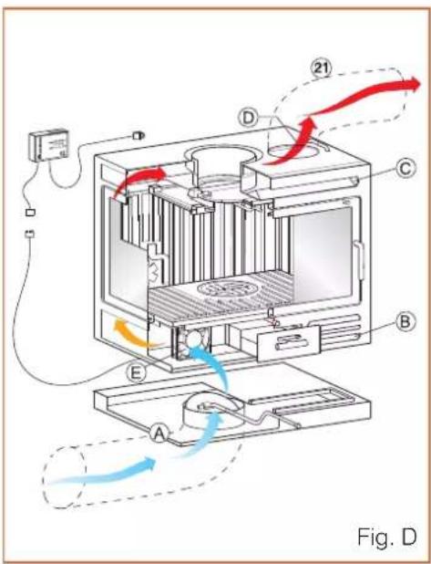
The air drawn from the outside through the special mechanism (A) is mixed with air drawn from the room through the lower grilles (B). The mixed air is then heated in the rear cavity and comes out into the room through the upper front grille (C).
This ensures replenishment of the air which leaves Firebox ^® through the fl ue during operation and at the same time heats the room.
Alternatively, the hot air may reach the room through an outlet connected to the holes in the upper part of Firebox® (D) with ∅ 14 cm aluminium pipes.
The air circulation described above may take place naturally by convection or with the help of two fans (E) housed in the base.
If the hot air is channelled into rooms other than the one in which Firebox ^® is installed, it is necessary to ensure an air return to the installation room through grilles at the bottom of the walls or gaps under the doors.
The pipe diameter must not be less than 14 cm so that the air does not exceed a speed of 5 m/s, thus avoiding irritating noises or excessive load losses owing to friction.
It is important that the path of the pipes is as straight as possible.
Aluminium pipes may be hidden within the ceiling or false beams, or built into walls; in
any case, they must be well insulated.
The ducting must be a maximum of 4 - 5 m long for Firebox ^® with natural convection and 6 - 7 m long for Firebox ^® with forced ventilation.
This length must be reduced by 1.2 m for each bend and for each outlet owing to load losses.
The product is supplied with two anti-corrosion discs (one on the outside and one on the inside of the combustion chamber). They must be removed during unpacking and disposed of as normal waste.
INSTALLATION OF HOT-AIR CIRCULATION KITS
There are three kits for ducting hot air that include everything necessary for the following three cases:
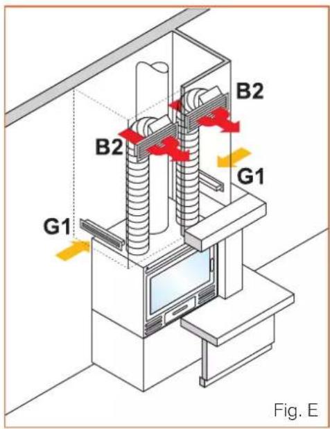
Kit one (Figs. D - E) only the fireplace room
- remove the two pre-cut plugs from the Firebox ^® cover by pressing inwards;
- fasten the two connectors on the holes in the hood;
- insert the two pipes and fi x them with the clamps provided;
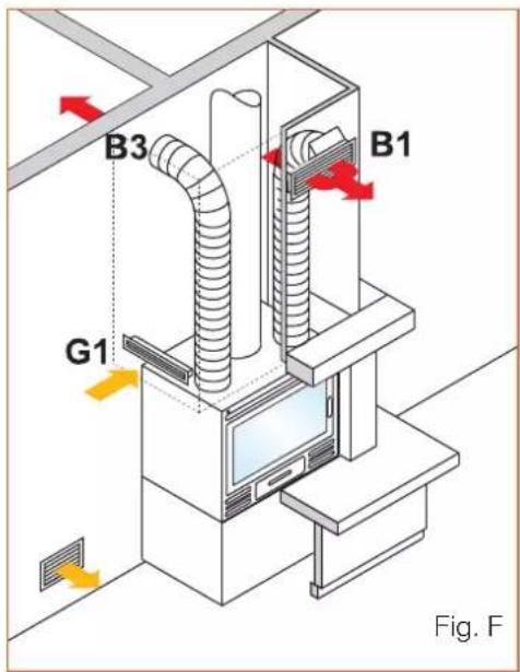
- attach the two outlet "B2" frames with connection pipe to the top of the mantel;
- attach the two slots "G1" to the bottom of the mantel;
- connect the two aluminium connection pipes and fasten with clamps; fit the two front grilles and click them into place.
Kit two (Fig. F) fireplace room, plus one adjacent room
Proceed as for kit one, fi tting one complete outlet "B1" to the top of the mantel instead of two "B2", and an outlet "B3" to the wall of the room to be heated. At the base of the mantel, only one slot "G1" is required.
Kit three (Fig. G) fireplace room, plus two adjacent rooms
Proceed as for kit one, fi tting the two "B3" outlets to the walls of the rooms to heat instead of the two "B2" outlets.
This kit entails the use of a slot (G1) in the top of the mantel to allow ventilation inside the mantel itself.
NATURAL CONVECTION
This occurs when the air circulates naturally in the cavity and ducting by exploiting convection (the physical principle that causes hot air to rise).
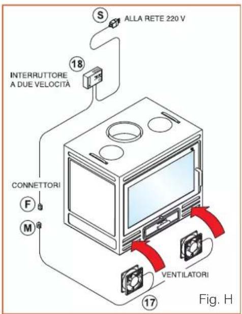
FORCED VENTILATION (Fig. H)
This is achieved with the use of two fans (17) inserted in the lower part of Firebox ^® , a temperature thermostat housed next to one of the two fans and a two-speed switch (18) to be placed near the fi replace.
Connecting the forced-ventilation equipment:
- connect the switch to the fans by inserting connector (M) into connector (F).
- connect the switch to the 230 VAC mains using the plug (S).
Operation of the two-speed switch:
- to start the fans, set the switch to "manual" (fi rst or second speed as desired).
- to stop the fans set the switch to "automatic"
N.B.: in the "automatic" position, the fans operate automatically when the air temperature is above 50°C, to prevent damage from excessive heat, and then they remain off at lower temperatures.

Start-up
During the initial start-up and after periods of inactivity, Firebox ^® must operate at moderate power; this in order to avoid damage due to too rapid a rise of temperature. During the first few ignitions, the paint and any processing oils may cause the formation of odour and smoke; in this case, ventilate the room well until the smell and smoke stop.
Hot-air circulation (convection air)
During operation, the grilles for the entry and exit of convection air must remain open to avoid the accumulation of heat in internal parts.
Ignition
1) do not use infl ammable liquids, such as gasoline or alcohol, for ignition. Always keep these liquids away from the body of Firebox®.
2) before ignition, check that:
▶ the damper for the entry of outside compensation air is fully open
▶ the smoke-outlet damper is completely open
▶ the grille for taking outdoor air into the room, generally installed on the mantel, is fully open
▶ the switch of the electronic equipment for the forced-ventilation models is on
Place crumpled paper on the fire surface.
Superimpose a first layer of smaller wood and a further layer of medium pieces (logs of ∅ 8-10 cm x 30-40 cm).
Light the paper and monitor combustion until the flame is well developed.
Close the door of the fi replace, tightening the handle; wait until a bed of embers has formed and then load the hourly quantity of wood required in two cycles.
Adjust combustion using the primary and secondary air dampers as required.
If there is not a suitable bed of embers, it must be created by burning small-medium pieces of wood and keeping the door completely open for the necessary time.
Forced ventilation (where applicable)
Before lighting Firebox ^® , set the switch to "ON".
The electrical components are always live so, before any maintenance, disconnect the plug and turn off the electrical panel of the dwelling.
Cleaning Firebox® and the fl ue
Have a specialized technician clean Firebox ^® , the smoke duct and the fl ue at least once a year and, if necessary, even more frequently.
Cleaning the glass
Firebox ^® is equipped with an air system for cleaning the glass to avoid premature dirtying.
To avoid excessive marking of the glass:
▶ never use moist wood as the water vapour is deposited on the glass, also holding particles of soot
▶ burn wood away from the glass to avoid contact with the flame
▶ clean the cold glass using special spray cleaner Glasskamin, marketed by Edilkamin
▶ avoid abrasive cleaners
Supply of external combustion air
During the operation of Firebox ^® , check that the room is continuously receiving sufficient outside air.
In fact, when operating with open or closed mouth, Firebox ^® requires a lot of air.
Do not modify the mechanisms for the intake of external combustion air.
You must check and ensure that, during the operation of Firebox ^® , the damper of the external air-intake mechanism is fully open.
Removing the ash
Empty the ash tray regularly.
Prevent the cone of ash from reaching the grill; this could damage the grille due to insufficient air cooling.
Never remove hot ashes using a vacuum cleaner and do not throw them in the garbage before they are completely cool.
natural_image
Exterior view of a modern industrial stove with visible flames and smoke (no text or symbols)natural_image
Exterior view of a black industrial stove burner with visible flames and wood shavings (no text or symbols)natural_image
Close-up of a metallic electronic component with a circular symbol and a star mark, no visible text or symbols.natural_image
Modern black industrial stove with visible flames and a metal frame (no text or symbols)natural_image
Close-up of a metallic rectangular object with a circular emblem and a star symbol, no readable text or symbols present.natural_image
Modern portable stove with visible flames and wood shavings (no text or symbols)natural_image
Exterior view of a modern fire extinguisher with visible flames and wood inside (no text or symbols)natural_image
Exterior view of a black portable stove with visible flames and smoke (no text or symbols)Riga 49
natural_image
Modern portable stove with visible flames and smoke, placed on a reflective surface (no text or symbols)natural_image
Modern portable stove with visible flames inside, placed on a reflective surface (no text or symbols)natural_image
3D mechanical component diagram with arrows indicating force or movement, no visible text or symbols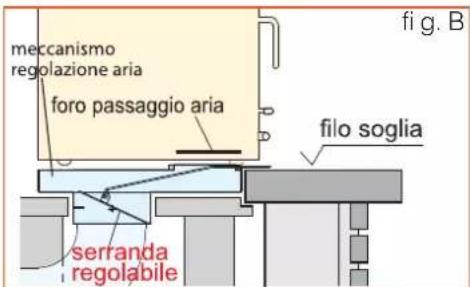
natural_image
Exterior view of a modern industrial stove with visible flames and smoke (no text or symbols)natural_image
Modern black industrial stove with visible flames and a metal frame (no text or symbols)natural_image
Close-up of a metallic electronic device with a circular emblem and a star symbol, no readable text or labels present.natural_image
Modern black box with visible flames inside, placed on a white surface (no text or symbols)natural_image
Close-up of a metallic rectangular device with a circular emblem and a star symbol, no readable text or labels present.natural_image
Modern portable stove with visible flames and wood shavings (no text or symbols)natural_image
Exterior view of a modern fire extinguisher with visible flames and smoke inside (no text or symbols)natural_image
Exterior view of a black portable stove with visible flames and cooling effect (no text or symbols)Riga 49
natural_image
Black portable stove with visible flames and cooling effect, placed on a reflective surface (no text or symbols)natural_image
Modern portable stove with visible flames inside, placed on a reflective surface (no text or symbols)natural_image
3D mechanical component diagram showing internal cavity and flow direction arrows (no text or symbols)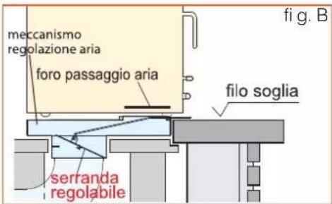
natural_image
Exterior view of a modern industrial stove with visible flames and smoke (no text or symbols)natural_image
Exterior view of a black industrial stove burner with visible flames and wood shavings (no text or symbols)natural_image
Close-up of a metallic rectangular object with a circular emblem and a star mark, no visible text or symbols.natural_image
Modern black box with visible flames inside, placed on a curved surface (no text or symbols)natural_image
Close-up of a metallic vehicle front panel with a circular emblem and a star symbol (no readable text or numbers)natural_image
Modern portable stove with visible flames and wood shavings (no text or symbols)natural_image
Exterior view of a modern fire extinguisher with visible flames and smoke inside (no text or symbols)natural_image
Exterior view of a black portable stove with visible flames and smoke, placed on a reflective surface (no text or symbols)Riga 49
natural_image
Modern portable stove with visible flames and smoke, placed on a reflective surface (no text or symbols)natural_image
Modern portable stove with visible flames inside, placed on a tiled floor (no text or symbols)natural_image
3D mechanical component diagram with blue arrows indicating force or movement, labeled Abb. A (no text or symbols on the object itself)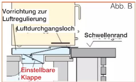
natural_image
Exterior view of a modern industrial stove with visible flames and smoke (no text or symbols)natural_image
Modern black industrial stove with visible flames and a metal frame (no text or symbols)natural_image
Close-up of a metallic device with a circular emblem and a star symbol, no readable text or labels present.natural_image
Modern black box with visible flames inside, placed on a white surface (no text or symbols)natural_image
Close-up of a metallic rectangular object with a circular emblem and a star symbol, no readable text or numbers present.natural_image
Modern portable stove with visible flames and wood shavings (no text or symbols)natural_image
Exterior view of a modern fire extinguisher with visible flames and smoke inside (no text or symbols)natural_image
Exterior view of a modern black portable stove with visible flames and internal structure (no text or symbols)Riga 49
natural_image
Modern portable stove with visible flames and smoke, placed on a reflective surface (no text or symbols)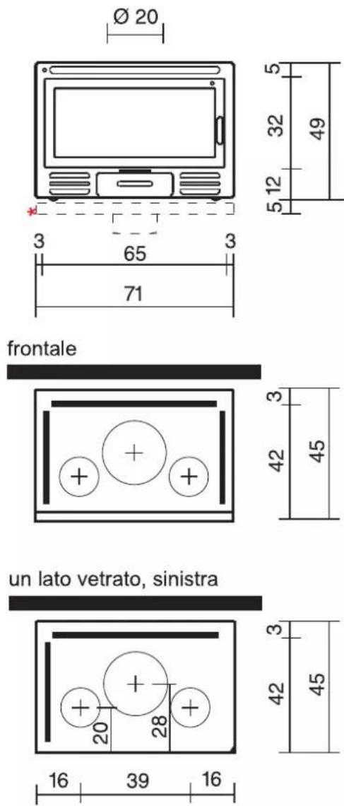
natural_image
Modern portable stove with visible flames inside, placed on a tiled floor (no text or symbols)Moldura de contorno da boca opcional.
natural_image
3D mechanical component diagram with arrows indicating force or movement, labeled 'fig. A' at bottom (no text or symbols on the object itself)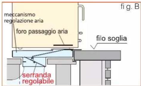

- General note Protections
- uel
- Protection from burns
- Recommended wood types
- so, burning moist wood means obtaining less heat
- FIREBOX®
- Quick installation one-piece fireplace:
- Available in 5 series and 17 versions: with cast-iron front
- with steel front
- with glass front
- Technical features:
- Single-piece, pre-assembled:
- Cast-iron/vermiculite combustion chamber:
- Post combustion\*:
- Hot-air ducting:
- External air-intake mechanism:
- Forced ventilation:
- Self-closing door\*:
- Glazed side:
- Glazing:
- cast-iron front
- DECO
- glass front
- LUCE PLUS/S 62
- LUCE PLUS/S 54
- steel front
- LUCE 62
- LUCE 54
- RIGA 49 - RIGA 49/1L
- RIGA 54
- WARNINGS
- Installing Firebox®
- Using Firebox®
- Electrical connections (for forced ventilation versions)
- EXTERNAL AIR INTAKE (Figs. A-B)
- FLUES (Fig. N)
- INSTALLATION IN AN EXISTING FIREPLACE FITTED WITH EXTERNAL AIR INTAKE
- INSTALLATION IN AN EXISTING FIREPLACE WITHOUT EXTERNAL AIR INTAKE
- If it is not possible to do as described above, place a 80/200 cm 4 external air in-
- INSTALLATION WITH A NEW, SPECIALLY MADE COVERING
- HOT-AIR CIRCULATION AND DUCTING (Fig. D, page 26)
- INSTALLATION OF HOT-AIR CIRCULATION KITS
- Kit one (Figs. D - E) only the fireplace room
- Kit two (Fig. F) fireplace room, plus one adjacent room
- Kit three (Fig. G) fireplace room, plus two adjacent rooms
- NATURAL CONVECTION
- FORCED VENTILATION (Fig. H)
- Connecting the forced-ventilation equipment:
- Operation of the two-speed switch:
- Start-up
- Hot-air circulation (convection air)
- Ignition
- Forced ventilation (where applicable)
- Cleaning Firebox® and the fl ue
- Cleaning the glass
- Supply of external combustion air
- Removing the ash
Brand : EDILKAMIN
Model : FIREBOX
Category : Fireplace