IDRO 50 - Fireplace EDILKAMIN - Free user manual and instructions
Find the device manual for free IDRO 50 EDILKAMIN in PDF.


User questions about IDRO 50 EDILKAMIN
0 question about this device. Answer the ones you know or ask your own.
Ask a new question about this device
Download the instructions for your Fireplace in PDF format for free! Find your manual IDRO 50 - EDILKAMIN and take your electronic device back in hand. On this page are published all the documents necessary for the use of your device. IDRO 50 by EDILKAMIN.
USER MANUAL IDRO 50 EDILKAMIN
natural_image
Exterior view of a black industrial stove with visible flames and vented door (no text or symbols)natural_image
Exterior view of a black industrial stove with visible flames and smoke (no text or symbols)UK Installation, use and maintenance pag. 18
F Installation, usage et maintenance pag. 34
natural_image
Exterior view of a portable industrial machine with visible internal components and labeled ports (E), no text or symbols present.natural_image
Technical line drawing of a mechanical assembly with no visible text or symbols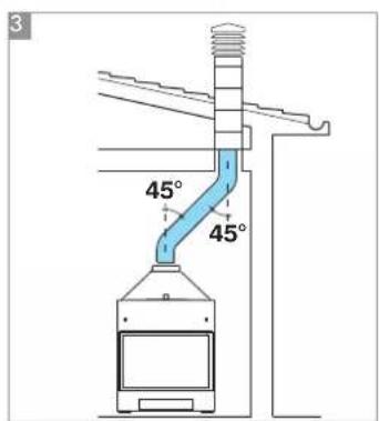
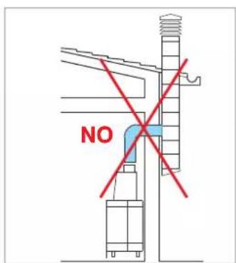
fig.A
natural_image
Mechanical assembly with pipes and housing components (no visible text or symbols)KIT 1
cod. 261880
ESEMPIO DI IMPIANTO IDRAULICO PER TERMOCAMINETTO SENZA PRODUZIONE DI ACQUA CALDA SANITARIA + CALDAIA MURALE CON UTILIZZO DI
KIT 2
flowchart
graph TD
    A["RE"] --> B["ST"]
    B --> C["TC"]
    C --> D["Ja"]
    D --> E["SC 30"]
    E --> F["VST"]
    F --> G["P"]
    G --> H["VSP"]
    H --> I["CA"]
    I --> J["MI"]
    J --> K["collettore"]
    K --> L["RA"]
    L --> M["RI"]
    M --> N["T"]
    N --> O["ACS"]
    O --> P["VA"]
    P --> Q["VR"]
    Q --> R["CA"]
    R --> S["AF"]
    S --> T["VI"]
    T --> U["VA"]
    U --> V["VR"]
    V --> W["CA"]
    W --> X["AF"]
    X --> Y["VI"]
    Y --> Z["VA"]
    Z --> AA["VR"]
    AA --> AB["CA"]
    AB --> AC["AF"]
    AC --> AD["VI"]
    AD --> AE["VA"]
    AE --> AF["VR"]
AF: Acqua Fredda
CA: Caldaia murale
6 Raccorderia in rame
natural_image
Industrial piping system with valves and a control panel, mounted on a metal frame (no visible text or symbols)KIT 2
cod. 261890
ESEMPIO DI IMPIANTO IDRAULICO PER TERMOCAMINETTO CON PRODUZIONE DI ACQUA CALDA SANITARIA + CALDAIA MURALE
CON UTILIZZO DI
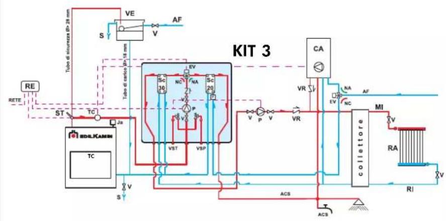
KIT 3
flowchart
graph TD
    A["RE"] --> B["ST"]
    B --> C["TC"]
    C --> D["Ja"]
    D --> E["SC 30"]
    E --> F["SC 20"]
    F --> G["P"]
    G --> H["VST"]
    H --> I["VSP"]
    I --> J["ACS"]
    J --> K["ACS"]
    K --> L["COLLETTORE"]
    L --> M["MI"]
    M --> N["RA"]
    N --> O["V"]
    O --> P["VI"]
    P --> Q["RI"]
    Q --> R["ACS"]
    R --> S["ACS"]
    S --> T["VA"]
    T --> U["CA"]
    U --> V["VR"]
    V --> W["NC"]
    W --> X["VA"]
    X --> Y["VA"]
    Y --> Z["VA"]
    Z --> AA["VA"]
    AA --> AB["VA"]
    AB --> AC["VA"]
    AC --> AD["VA"]
    AD --> AE["VA"]
    AE --> AF["VA"]
    AF --> AG["VA"]
    AG --> AH["VA"]
    AH --> AI["VA"]
    AI --> AJ["VA"]
    AJ --> AK["VA"]
    AK --> AL["VA"]
    AL --> AM["VA"]
    AM --> AN["VA"]
    AN --> AO["VA"]
    AO --> AP["VA"]
    AP --> AQ["VA"]
    AQ --> AR["VA"]
    AR --> AS["VA"]
    AS --> AT["VA"]
    AT --> AU["VA"]
    AU --> AV["VA"]
    AV --> AW["VA"]
    AW --> AX["VA"]
    AX --> AY["VA"]
    AY --> AZ["VA"]
    AZ --> BA["VA"]
    BA --> BB["VA"]
    BB --> BC["VA"]
    BC --> BD["VA"]
    BD --> BE["VA"]
    BE --> BF["VA"]
    BF --> BG["VA"]
    BG --> BH["VA"]
    BH --> BI["VA"]
    BI --> BJ["VA"]
    BJ --> BK["VA"]
    BK --> BL["VA"]
    BL --> BM["VA"]
    BM --> BN["VA"]
    BN --> BO["VA"]
    BO --> BP["VA"]
    BP --> BQ["VA"]
    BQ --> BR["VA"]
    BR --> BS["VA"]
    BS --> BT["VA"]
    BT --> BU["VA"]
    BU --> BV["VA"]
    BV --> BW["VA"]
    BW --> BX["VA"]
    BX --> BY["VA"]
    BY --> BZ["VA"]
ACS: Acqua Calda Sanitaria
AF: Acquo Fredda
CA: Caldaia murale
6 Raccorderia in rame
natural_image
Industrial piping system with valves and valves mounted on a metal frame (no visible text or labels)KIT 3
cod. 261900
PER IL CORRETTO FUNZIONAMENTO OCCORRE INCROCIARE I TUBI DI MANDATA E DI RITORNO
ESEMPIO DI IMPIANTO IDRAULICO PER TERMOCAMINETTO CON PRODUZIONE DI ACQUA CALDA SANITARIA + CALDAIA MURALE
CON UTILIZZO DI
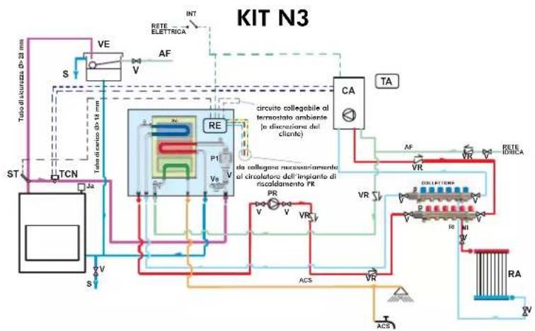
KIT N3
flowchart
graph TD
    A["TUBO di-scurezza D=22 mm"] --> B["VE"]
    B --> C["S"]
    C --> D["TCN"]
    D --> E["Ja"]
    E --> F["ST"]
    F --> G["RC"]
    G --> H["VA"]
    H --> I["RE"]
    I --> J["P1"]
    I --> K["Vs"]
    I --> L["VA"]
    L --> M["CA"]
    M --> N["TA"]
    N --> O["RETTE ELETTRICA"]
    O --> P["INT"]
    P --> Q["RA"]
    Q --> R["ACS"]
    R --> S["ACS"]
    S --> T["RC"]
    T --> U["VA"]
    U --> V["ACS"]
    V --> W["ACS"]
    W --> X["RC"]
    X --> Y["VA"]
    Y --> Z["ACS"]
    Z --> AA["ACS"]
    AA --> AB["RC"]
    AB --> AC["VA"]
    AC --> AD["ACS"]
    AD --> AE["ACS"]
    AE --> AF["RC"]
    AF --> AG["VA"]
    AG --> AH["ACS"]
    AH --> AI["ACS"]
    AI --> AJ["RC"]
    AJ --> AK["VA"]
    AK --> AL["ACS"]
    AL --> AM["ACS"]
    AM --> AN["RC"]
    AN --> AO["VA"]
    AO --> AP["ACS"]
    AP --> AQ["ACS"]
    AQ --> AR["RC"]
    AR --> AS["VA"]
    AS --> AT["ACS"]
    AT --> AU["ACS"]
    AU --> AV["RC"]
    AV --> AW["VA"]
    AW --> AX["ACS"]
natural_image
Pure electrical circuit lines without any symbolsKIT N3
cod. 627690
IMPIANTO PER INSTALLAZIONE A VASO APERTO
ESEMPIO DI IMPIANTO IDRAULICO PER TERMOCAMINETTO CON PRODUZIONE DI ACQUA CALDA SANITARIA + CALDAIA MURALE
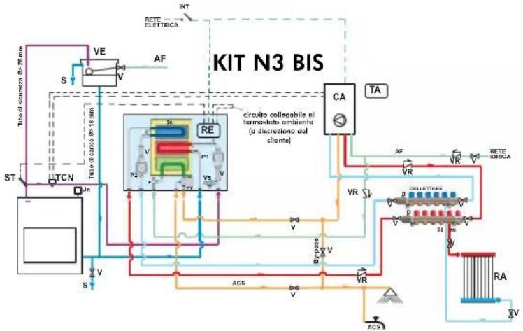
CON UTILIZZO DI KIT N3 BIS
flowchart
graph TD
    A["Tube di sciametta 0-71 mm"] --> B["VE"]
    B --> C["S"]
    C --> D["TCN"]
    D --> E["Jn"]
    E --> F["S"]
    F --> G["Re"]
    G --> H["P2"]
    H --> I["P1"]
    I --> J["V1"]
    J --> K["V2"]
    K --> L["CA"]
    L --> M["TA"]
    M --> N["RETTE ETRICA"]
    N --> O["RA"]
    O --> P["V"]
    Q["BY pass"] --> R["V"]
    S["ACS"] --> T["V"]
    U["VR"] --> V["RELATIONS"]
    W["RF"] --> X["RE"]
    Y["ACS"] --> Z["ACS"]
    AA["RF"] --> AB["RF"]
    AC["RF"] --> AD["RF"]
    AE["RF"] --> AF["RF"]
    AG["RF"] --> AH["RF"]
    AI["RF"] --> AJ["RF"]
    AK["RF"] --> AL["RF"]
    AM["RF"] --> AN["RF"]
    AO["RF"] --> AP["RF"]
    AQ["RF"] --> AR["RF"]
    AS["RF"] --> AT["RF"]
    AU["RF"] --> AV["RF"]
    AW["RF"] --> AX["RF"]
CA Caldaia murale
natural_image
Pure electrical circuit lines without any symbolsKIT N3 BIS
cod. 627860
ESEMPIO DI IMPIANTO IDRAULICO PER TERMOCAMINETTO CON PRODUZIONE DI ACQUA CALDA SANITARIA IN ACCUMULO + CALDAIA MURALE
CON UTILIZZO D
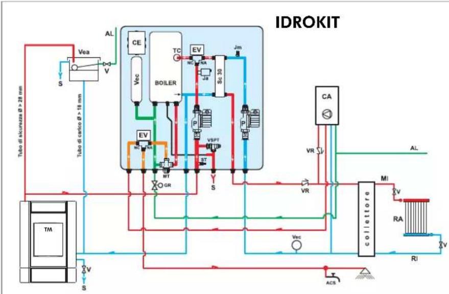
IDROKIT
flowchart
graph TD
    A["Tubo di carico @ > 18 mm"] --> B["VEa"]
    B --> C["S"]
    C --> D["TC"]
    D --> E["BOILER"]
    E --> F["EV"]
    F --> G["SC 30"]
    G --> H["Jm"]
    H --> I["VA"]
    I --> J["CA"]
    J --> K["AL"]
    K --> L["Collettore"]
    L --> M["MI"]
    M --> N["RA"]
    N --> O["RI"]
    O --> P["V"]
    P --> Q["ACS"]
    Q --> R["Valve"]
    R --> S["Valve"]
    S --> T["Valve"]
    T --> U["Valve"]
    U --> V["Valve"]
    V --> W["Valve"]
    W --> X["Valve"]
    X --> Y["Valve"]
    Y --> Z["Valve"]
    Z --> AA["Valve"]
    AA --> AB["Valve"]
    AB --> AC["Valve"]
    AC --> AD["Valve"]
    AD --> AE["Valve"]
    AE --> AF["Valve"]
    AF --> AG["Valve"]
    AG --> AH["Valve"]
    AH --> AI["Valve"]
    AI --> AJ["Valve"]
    AJ --> AK["Valve"]
    AK --> AL["Valve"]
    AL --> AM["Valve"]
ACS: Acqua Calda Sanitaria
AF: Acqua Fredda
natural_image
Industrial equipment setup with pressure regulator and piping (no visible text or symbols)KIT 5
cod. 280590
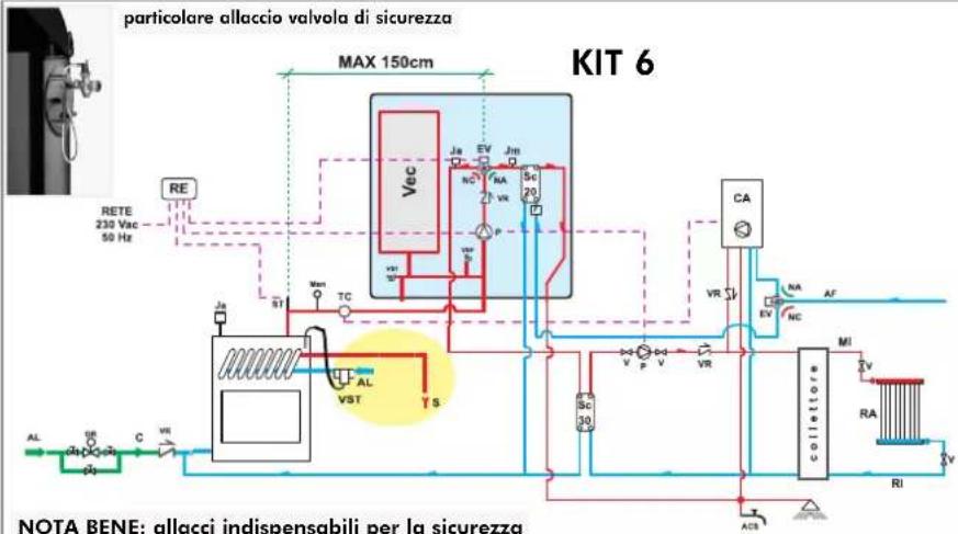
ACS: Acqua Caldo Sanitaria
AF: Acqua Fredda
natural_image
Industrial equipment setup with pressure vessel, pipes, and control panel (no visible text or symbols)KIT 6
cod. 280600
REGOLATORE ELETTRONICO (KIT 1-2-3-5-6)
natural_image
Front view of a handheld electronic device with control knobs and display (no visible text or symbols)natural_image
Three different types of industrial valve fittings (no text or symbols visible)natural_image
Close-up of a metallic T-joint valve with coiled cable (no text or symbols visible)natural_image
Exterior view of a handheld electronic device with control panel and wiring (no visible text or symbols)natural_image
Mechanical sensor device with black housing and coiled cable (no visible text or symbols)natural_image
Close-up of a mechanical component with metallic and black casing (no visible text or symbols)Circolatore UPS 25-50 cod. 219660 UPS 25-60 cod. 238270
natural_image
Two metallic rectangular electronic components with four mounting holes (no text or symbols visible)natural_image
Black rectangular electronic component with three ports and a label (no readable text or symbols)natural_image
Simple line drawing of a resistor and a plug (no text or symbols)Girarrosto Idro 50-70 cod. 234560 Idro 100 cod. 236710
Dear Sir / Madam,
Thank you for having chosen IDRO 50-70-100.
You are kindly asked to read through this information booklet before using the fireplace in order for you to make use of all its features in total safety.
For further clarification or assistance, please contact the Dealer.
Please note that a qualified dealer MUST install the fireplace as is stipulated in the Italian Ministerial Decree No. 37 ex Italian Law No. 46/90.
For installations implemented outside Italy, please refer to the local regulations in the country of use. The manufacturer cannot be held liable for any damage caused as a result of incorrect installation, incorrect maintenance procedures and improper use.
IMPORTANT WARNINGS:
The thermo fireplace must never function without water in the system.
It can be damaged if it is ignited with no water in the system.
- The thermo fireplace is designed to heat water by means of automatic combustion of wood in the hearth.
- The only hazards that can derive from using the thermo fireplace pertain to non-compliance with the installation regulations, direct contact with live electrical parts (external), contact made with the fire and hot parts or foreign substances being put in the fireplace.
- No flammable products are to be used to clean the smoke channel.
- The hearth must only be cleaned with a vacuum cleaner when COLD.
- The glass can be cleaned when COLD with a suitable product (e.g. GlassKamin) and a cloth. Do not clean when hot.
- The exhaust pipes and the door become very hot when the thermo fireplace is used.
- Do not place anything, which is not heat resistant close to the thermo fireplace.
- NEVER use liquid fuel to ignite the thermo fireplace or to rekindle the embers.
- Do not obstruct the air inlets in the room where the fireplace is installed or the air inlets of the thermo fireplace itself.
- Do not wet the thermo fireplace and do not go near electrical parts with wet hands.
- Do not use reducers on the smoke exhaust pipes.
- The thermo fireplace must be installed in a place which is suitable for fire prevention and equipped with all that is required (power and air inlets/outlets) for it to function properly and safely (refer to the indications given in these technical specifications).
WARNING:
In the list of parts, a code number is given and this must be quoted if a request for spare parts is made.
The undersigned EDILKAMIN S.p.a. with head offi ce headquarters at Via Vincenzo Monti 47 - 20122 Milano - Italy - VAT 0192220192
Declares under its own responsibility as follows:
The wood Thermo Fireplaces illustrated below conforms to Regulation EU 305/2011 (CPR) and to the harmonised European Standard EN 13229:2001 - A1:2003 - A2:2004 - AC:2006 - AC:2007
THE WOOD THERMO FIREPLACES, trademark ITALIANA CAMINI, called IDRO 50-70-100
YEAR OF MANUFACTURE: Ref. Data nameplate
Declaration of performance (DoP - EK 004-005-006) Ref. Data nameplate
EDILKAMIN S.p.a. will decline all responsibility of malfunctioning or damage to the equipment in case of unauthorized substitution, assembly or modifications of any sort on the said equipment on the part of non-EDILKAMIN personnel.
TECHNICAL DATA
| Specifications | 50/50CS | 70 | 100 | |
| Thermal output (burnt) kW 23 29,4 34,5 | ||||
| Power output | kW 18 23 27 | |||
| Overall efficiency % 78,3 78,3 78,3 | ||||
| Efficiency to the water % ~ 70 ~ 70 ~ 70 | ||||
| Optimal wood consumption kg/h 5 6,4 7,5 | ||||
| Total weight including the packaging (min-max) | kg | 171/189 | 184/230 | 251/302 |
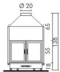
| ø female smoke outlet | cm 18 20 25 | |||
| ø stainless steel chimney flue for a height ranging from 3 to 5 m | cm | 20 | 25 | 25 |
| ø stainless steel chimney flue for a height ranging from 5 to 7 m | cm | 18 | 22 | 25 |
| ø stainless steel chimney flue for a height exceeding 7 m | cm | 18 | 20 | 22 |
| ø external air inlet | cm 10 10 10 | |||
| Water capacity | litres 60 70 90 | |||
| Maximum operating pressure | bar 1,5 1,5 1,5 | |||
| Hot sanitary water production (kit 1-3-n3-n3bis-6)* | l/min** | 10 12 14 | ||
| Heating capacity *** | m3 | 470 | 600 | 705 |
| System return | inches | 1" | 1"/4 | 1"/4 |
| System flow | inches | 1" | 1"/4 | 1"/4 |
* boiler temperature is 70°
** (ΔT=25K)
*** Insulation in accordance with the Legislative Decree 192/2005 ex Italian Law 10/91 and subsequent changes together with an expected heat output of 35 Kcal/m³ per hour.

IDRO 50 IDRO 50 CS fixed door leaf
GENERAL SAFETY REGULATIONS
(VALID ONLY FOR IDRO 50/CS)
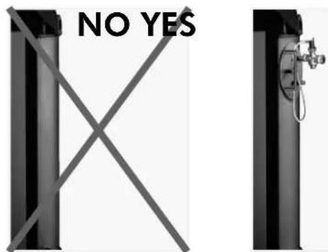
ONLY THERMO FIREPLACES THAT HAVE A THERMAL RELIEF VALVE WHICH ACTUATES THE COIL CAN BE INSTALLED ON CLOSED TANK SYSTEMS
Installations with a closed tank:
- The installer is responsible for the correct installation of the system, which is to be compliant with UNI standards 10683/2005 - 9615/90 - 10412:2
• The entire process must be carried out by qualified personnel in accordance with Italian Law No. 46/90
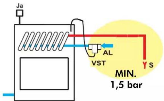
• The thermal relief valve (supplied by Italiana Camini) must be connected to the cooling circuit with a minimum pressure of 1.5 bar.
AL=P= coil power supply, always with a minimum pressure of 1.5 bar
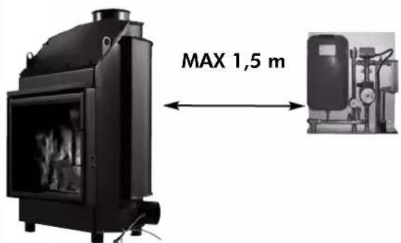
- KITS 5 and 6 must be installed within a MAX distance of 150 cm from the fireplace.
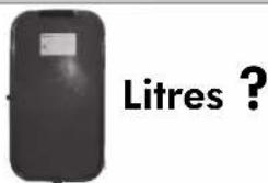
- Another expansion tank must be installed specifically for the thermo fireplace in accordance with the volume of water of the system.
1 Year
• The safety valve and the thermal relief valve must be checked at least once a year by qualified personnel in accordance with Italian Law No. 46/90
- THE THERMO FIREPLACE MUST NEVER FUNCTION WITHOUT WATER IN THE SYSTEM.
- THE THERMO FIREPLACE CAN BE DAMAGED IF IT IS IGNITED WITH NO WATER IN THE SYSTEM.
- The thermo fireplace is designed to heat water by means of wood combustion in the hearth.
- The only hazards that can derive from using the thermo fireplace pertain to non-compliance with the installation instructions, direct contact with live electrical parts (inside), contact made with the fire and hot parts or foreign substances being put in the fireplace.
- For the thermo fireplace to function properly installation must be carried out according to the instructions given in this booklet and the door must only be opened to refill the hearth with wood.
- Never put foreign substances in the hearth or in the tank.
- No flammable products are to be used to clean the smoke outlet channel.
- The glass can be cleaned when COLD with a suitable product (e.g. GlassKamin) and a cloth. Do not clean when hot.
- The exhaust pipes and the door become very hot when the thermo fireplace is used.
- Do not place anything that is not heat resistant close to the thermo fireplace.
- NEVER use liquid fuel to ignite the thermo fireplace or to rekindle the embers.
- Do not obstruct the external air inlets in the room where the fireplace is installed or the air inlets of the thermo fireplace itself.
- Do not wet the thermo fireplace and do not go near the electrical parts of the system with wet hands.
- Do not use reducers on the smoke exhaust pipes.
- The thermo fireplace must be installed in a place that is suitable against fire hazards and equipped with all that is required (power and air inlets/outlets) for it to function properly and safely.
OPEN TANK
- The connections, commissioning and verification of proper operation of the fireplace must be carried out by qualified personnel, who can implement all connections in accordance with the laws in force, particularly with Italian D.M 37 Law No. 46/90, apart from complying with these instructions.
- The thermo fireplace and the system are filled with water that flows from the water inlet pipe (the diameter must not be less than 18 mm) to the open expansion tank.
- All the vents of the radiators must be opened during this phase so as to prevent air pockets from forming in the system, which would obstruct the circulation of water.
NB:
- The open tank should be placed higher than 3 m from the highest radiator and lower than 15 m from the thermo fireplace outlet.
- In any case, the tank must be high enough to create a greater pressure than that produced by the pump (circulator).
- The system must never be filled directly from the water mains as the pressure may be greater than that stipulated on the data plate of the thermo fireplace.
- The safety pipe to the expansion tank must allow the water to flow freely, must not have taps and must be insulated properly.
- The water inlet pipe must not have taps nor curves.
- The maximum operating pressure must not exceed 1.5 bar
- The testing pressure is 3 bar.
- In places that reach very low temperatures, antifreeze liquid must be added to the water in the system.
-
Never ignite the fire in the thermo fireplace (not even as a test) unless the system is filled with water as this could cause irreparable damage.
-
Connect the drains of the thermal relief valve (TRV) and the safety valve (SV) (diagrams are found on the following pages).
- The flow test of the system must be carried out with the expansion tank open.
- It is recommended to install a 6 bar safety valve on the hot sanitary water circuit so as to drain any excessive increase in the volume of the water in the heat exchanger.
- Place all the components of the system (circulator, heat exchanger, valves, etc.) in easily accessible points for routine and special maintenance procedures.
- It is recommended to prepare thermal insulation on the vaulted top part of the boiler.
WATER TREATMENT
- If need be, antifreeze, descaling and anticorrosive solutions are to be added to the water. A softener must be used if the hardness of the water used to refill and top-up the system exceeds 35^ f (French degrees).
Please refer to UNI 8065-1989 standard (water treatment in domestic heating systems).
CLOSED TANK additional regulations to those specified above (VALID ONLY FOR IDRO 50/CS)
- Be careful not to exceed 1.5 bar when filling the system.
- All the vents of the radiators must be opened during this phase so as to prevent air pockets from forming in the system, which would obstruct the circulation of water.
- Only if a thermal relief valve actuates the coil can the fireplace be installed on a CLOSED TANK system.
- Consider the necessity of installing another CLOSED TANK.
- Make sure the drain is connected to the coil and the power supply is at least 1.5 bar.
- The upstream pressure of the cooling circuit must be at least 1.5 bar (UNI 10412/2 point 6.2).
Important advice regarding the installation
Other than that described in this documentation, you are also asked to note the following UNI standards:
- No. 10683 - firewood heat generators: installation requirements
- No. 9615/90 - calculating the internal dimensions of fireplaces
- No. 10412:2 - hot water heating systems. Specific safety requirements for systems provided with residential solid fuel burning appliances and combined boiler, not exceeding a total nominal heat input of 35 kW.
Particularly:
- Before carrying out any assembly it is important to verify compatibility of the appliance, as stipulated in UNI 10683 standard, paragraphs 4.1 / 4.1.1 / 4.1.2.
- When assembly is completed, the installer must implement "start-up operations" and issue documentation as required by UNI 10683 standard in paragraphs 4.6 and 5, respectively.
- The connections, commissioning and verification of proper operation of the fireplace must be carried out by qualified personnel, who can implement the electrical and plumbing connections as required by UNI standards 10683, paragraph 4.5 and 10412:2, apart from complying with these assembly instructions.
- Verification must be carried out with the fireplace on and after having been on for a couple of hours, before covering the fireplace, so that you can intervene if need be. After which, the finishing operations such as:
- setting-up the fireplace mantel
- mounting the fireplace covering
- pilasters, painting, etc.
are carried out, once the tests are completed successfully.
Consequently, Italiana Camini does not accept responsibility for expenses deriving from demolition as well as construction even if either occurs as a result, after having replaced any damaged parts of the fireplace.
External air inlet (optional)
An external connection with a 10 cm diameter crosssection throughout (refer to the technical table) is absolutely necessary for the thermo fireplace to function properly and is therefore imperative for this to be implemented.
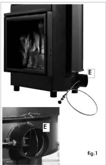
This connection must link the air adjustment mechanism (E), delivered separately. It can be installed on either the left side or the right side of the thermo fireplace.
This can be made of a flexible aluminium pipe.
Ensure that the points where there may be dispersion of air are sealed well.
The air adjustment mechanism (E) can be removed and mounted on the right side of the thermo fireplace.
It is recommended to place a protection grille on the outer part of the air inlet channel, however, ensure that this does not reduce the cross-section.
For distances longer than 3 m or with bends, increase the given cross-section by a minimum of 10% to a maximum of 20%.
The intake of external air must enter at floor level (it cannot enter from above).
natural_image
Exterior view of a portable industrial machine with internal components and labeled ports (E), shown from two angles (no text or symbols on the device itself)Note: The product is supplied with two anti-corrosion discs (one on the outside and one on the inside of the combustion chamber). They must be removed during unpacking and disposed of as normal waste.
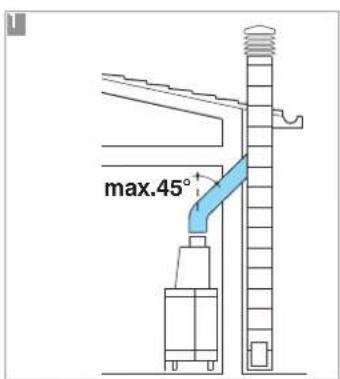
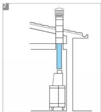
Chimney flues and chimneypot
The thermo fireplace smoke outlet has a circular crosssection so that stainless steel pipes can be used.
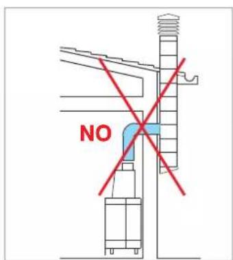
If the chimney flue inlet is not vertically above the thermo fireplace, the connection from the fireplace to the flue must not have a narrowing section or inclinations greater than 45^
(fig. A 1-2-3).
If the chimney flue is not brand new or too big, it is recommended to fit in stainless tubes of an appropriate diameter and with suitable insulation.
If the chimney flue is installed outside, it is recommended to use an insulated, double walled, stainless steel flue.
The characteristics of the construction must be suitable to withstand a smoke temperature of at least 450°C, with particular reference to the mechanical resistance, insulation and the gas tight sealing.
The junction of the steel flue inlet and the smoke outlet of the fireplace must be sealed with high temperature mastic.
The fundamental characteristics of the chimney pot are:
- an internal cross-section at the base, which is the same as that of the chimney flue.
- an outlet cross-section which is no smaller than twice that of the chimney flue.
- its position must be high enough to catch the wind and avoid downdraft areas in turbulent wind.
In addition to that mentioned above, please consider the indications stipulated in UNI 10683 standard, paragraph 4.2: "connection to the smoke outlet system" and its subsections.
natural_image
Technical line drawing of a mechanical assembly with no visible text or symbols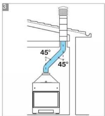
Transporting the fireplace
In order to facilitate transportation, the fireplace can be made lighter by removing the following:
- the base of the hearth and the ash grill made of cast iron and the ash-pan.
- the door.
Fireplace
To decide upon the exact positioning of the fireplace, it is important to verify which covering will be applied.
The positioning is implemented according to the model chosen (refer to the installation instructions found inside the packaging of each fireplace covering).
Always ensure the thermo fireplace is level during the installation process.
- Drill a hole into the wall or the flooring for the external air intake and connect the air adjustment mechanism to the hole as described in the chapter called "external air inlet".
- Use a stainless steel flue to connect the fireplace to the chimney flue, adhering with the diameters indicated in the specifications table and the guidelines given in the chapter called "chimney flues".
- Verify that all moving parts function properly before setting the thermo fireplace covering in place.
- This system must be tested and ignited for the first time before the covering is set in place.
Installation of the fireplace covering, fireplace mantel and ventilation outlets (Fig. F)
The base of the fireplace covering must allow the internal air to be recycled. Failing to do so, the fireplace will not function properly with possible smoke backflow.
Therefore, suitable slots or apertures must be made for the air to pass through.
Parts of the fireplace covering that are made of marble, stone and bricks must be mounted with a small gap between them and the fireplace so as to prevent possible breakage due to expansion and excessive overheating.
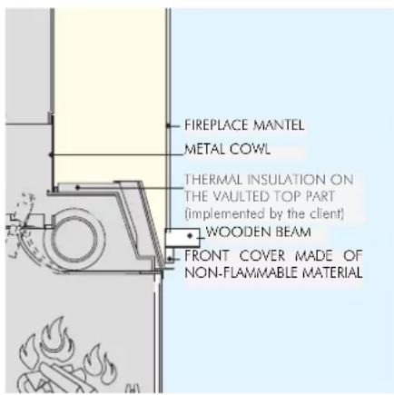
Wooden parts must be protected by fire resistant panels and no part must touch the thermo fireplace,
on the contrary, there must be an appropriate distance of at least 1 cm to allow the air to flow, preventing heat accumulation.
The fireplace mantel can be made of fireproof plasterboard panels or gypsum board.
Air should be allowed to flow inside the fireplace mantel (through the gap between the door and the beam). Through convective motion, the air will flow out from the grille installed at the top, resulting in heat recovery and preventing excessive overheating.
The fireplace mantel must have appropriate openings to carry out maintenance on the fittings.
In addition to that mentioned above, please consider the indications stipulated in the UNI 10683 standard, paragraphs 4.4 and 4.7: "insulation, finishing, fireplace covering and safety recommendations".
Insulating mats must be applied when using an installation KIT so as to protect it from the heat radiation emitted by the fireplace.
Important advice when using the fireplace
- It is important to ensure that there is water in the thermo fireplace and the system before igniting the fireplace. It is recommended to connect the inlet and outlet pipes as shown in the diagrams.
- The maximum operating pressure must not exceed 1.5 bar
- The Company is responsible for the proper functioning of the product only if this is handled in accordance with the documentation supplied with the product itself.
- First ignition (or re-igniting): remove any ash residue from the hearth.
Practical advice
- It is recommended to keep the radiators closed in the room where the thermo fireplace is installed since the heat radiated from the opening of the fireplace itself is enough.
- An incomplete combustion process causes excessive fouling on the heat exchanger pipe. To prevent this you must:
- burn dry wood.
- ensure the hearth contains a bed of embers and burning carbon before adding more wood.
- place larger logs together with smaller ones.
Igniting the fireplace
- Ensure that at least one radiator is always open.
- Actuate the switches of the electronic regulator.
- Place a pile of medium-thin dry wood in the thermo fireplace and ignite the fire.
-
Wait a few minutes until it reaches sufficient combustion.
-
Close the door
- Adjust the combustion setting via the damper control at the front.
- Set the thermostat on the electronic regulator (*) at a temperature between 50 and 70°C.
- The 3-way valve (*) diverts the water flow directly to the thermo fireplace; when the set temperature is reached, the 3-way valve (*) diverts the flow to the system.
- When the door is closed, the damper by-pass automatically diverts the combustion smoke, thus improving the efficiency.
- When the door is opened, the damper bypass opens automatically, allowing the smoke to reach the smoke flue directly, preventing it from coming out of the inlet.
(*) these components of the system are to be provided by the installer.
During the combustion process
If the water temperature exceeds 90^ C because of too much wood being placed in the hearth, the thermal relief valve will be activated and the acoustic signal heard.
In this case you must proceed as follows:
- Wait until the temperature is lower than 80^ C; check the warning lights on the electronic regulator.
- The hot water tap can be opened to speed up the cooling process if the thermo fireplace is equipped with hot sanitary water.
Adjusting the air
- The damper control found on the external air inlet (refer to Fig. 1 on pg. 6), regulates the amount of primary air that is necessary for the combustion process. Pushing the knob will close the external air inlet and pulling the knob will open it.
Maintenance
Cleaning the hearth
- Fouling that tends to accumulate on the internal walls of the thermo fireplace decreases the efficiency of heat transfer.
- It is therefore necessary to clean the fireplace regularly, by bringing the water temperature to 80 / 85°C to soften the fouling and then remove this with a steel spatula.
Cleaning and replacing the glass
- Use an appropriate spray for ceramic glass to clean the glass.
- The glass must be cleaned when cold.
- If the glass must be replaced, remove the self-tapping screws and fibreglass gasket before removing the glass holder profiles.
- Ensure the gasket is inserted in place before setting the glass back in place.
\* optional components
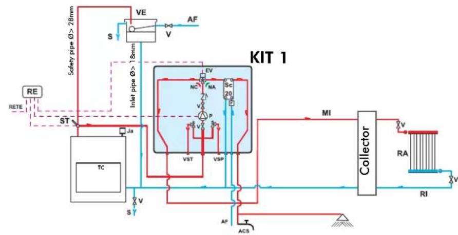
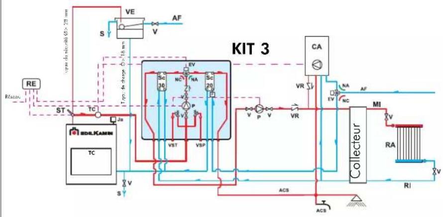
AN EXAMPLE OF A HYDRAULIC SYSTEM FOR A THERMO FIREPLACE WITH HOT SANITARY WATER PRODUCTION
USING
KIT 1
flowchart
graph TD
    A["RE"] --> B["ST"]
    B --> C["Ja"]
    C --> D["TC"]
    D --> E["S"]
    E --> F["VE"]
    F --> G["S"]
    G --> H["Inlet pipe Ø > 18mm"]
    H --> I["SC"]
    I --> J["VST"]
    I --> K["VSP"]
    J --> L["MC"]
    K --> M["NC"]
    L --> N["PA"]
    M --> O["PA"]
    N --> P["ACS"]
    O --> Q["ACS"]
    P --> R["MT"]
    Q --> S["MT"]
    R --> T["Collector"]
    S --> T
    T --> U["RA"]
    U --> V["RI"]
    V --> W["v"]
    W --> X["MT"]
    X --> Y["ACS"]
    Y --> Z["ACS"]
    Z --> AA["MT"]
    AA --> AB["ACS"]
    AB --> AC["MT"]
    AC --> AD["ACS"]
    AD --> AE["MT"]
    AE --> AF["ACS"]
    AF --> AG["MT"]
    AG --> AH["ACS"]
    AH --> AI["MT"]
    AI --> AJ["ACS"]
    AJ --> AK["MT"]
    AK --> AL["ACS"]
    AL --> AM["MT"]
    AM --> AN["ACS"]
    AN --> AO["MT"]
ACS: Hot Sanitary Water
AF: Cold Water
EV: 3-way Solenoid Valve
F: Flow Switch
MI: System Flow
NA: Normally Open
NC: Normally Closed
P: Pump (circulator)
RA: Radiators
RE: Electronic Regulator
RI: System Return
S: Drain
Sc 20: 20-plate Heat Exchanger
ST: Temperature Sensor
TC: Thermo Fireplace
V: Valve
VE: Open Expansion Tank
VSP: 1.5 bar Pressurized Safety Valve
VST: Thermal Relief Valve
Ja: Automatic Relief Valve
Kit 1 is designed to facilitate the work carried out by the installers. In fact, it consists of all the necessary components for the product to be properly installed.
NB: insulating mats must be applied so that the components of the kit are well-protected from the heat radiation emitted by the fireplace.
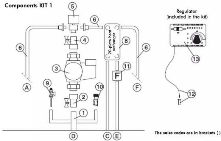
1 1" Male-Female Brass Collector
2 1" Ball Valve
3 Circulator with 1½" Fasteners (219660)
4 1" Check Valve (261910)
5 1" Male-Female 3-way Solenoid Valve (143330)
6 Copper Fittings
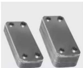
7 30-plate Heat Exchanger for heat transfer with the gas boiler circuit (216620)
8 20-plate Heat Exchanger for hot sanitary water production (205270)
9 3/4" Thermal Relief Valve (72940)
10 3/4" 1.5 bar Safety Valve (143260)
11 Flussostato (220830)
12 1/2" Thermometer Well + Sensor (175960)
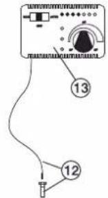
13 Electronic Regulator (220780)
A 3/4" System Return
B 3/4" System Flow
c 3/4" Fireplace Return
D 1" Fireplace Flow
E 1/2" Cold Sanitary Water
F 1/2" Hot Sanitary Water
Electrical Connections
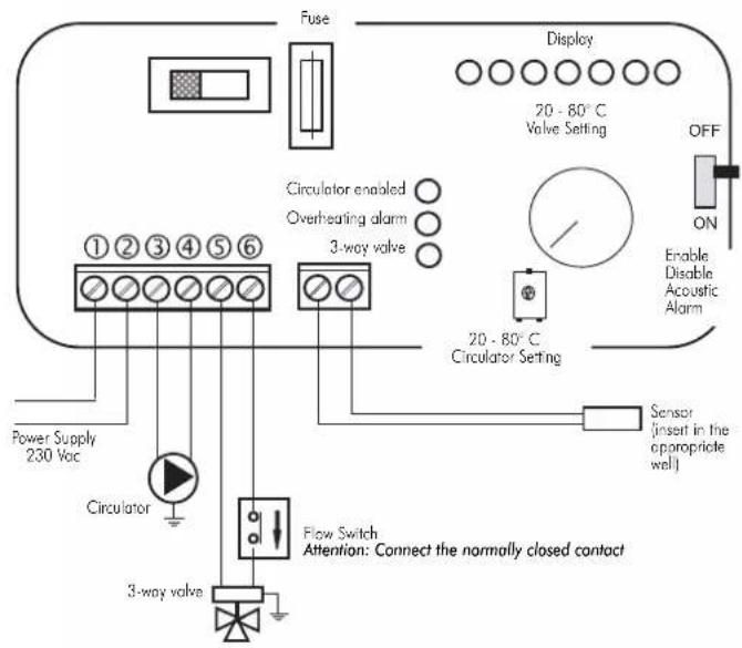
SELECTOR FUNCTIONS
Selector: OFF Everything is switched off
Selector: MAN Driven Circulator
Valve is set
Selector: AUTO Circulator is set
Valve is set
Alarm selection No acoustic signal in the
OFF position
natural_image
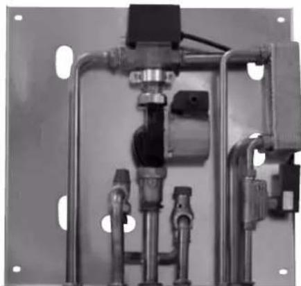
Mechanical assembly with pipes and housing components (no visible text or symbols)KIT 1
code 261880
THE INLET AND OUTLET PIPES MUST BE CROSSED FOR THE KIT TO FUNCTION PROPERLY
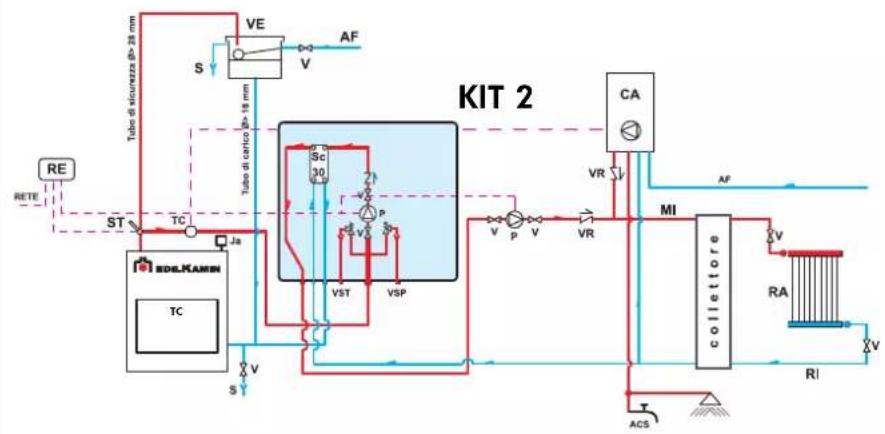
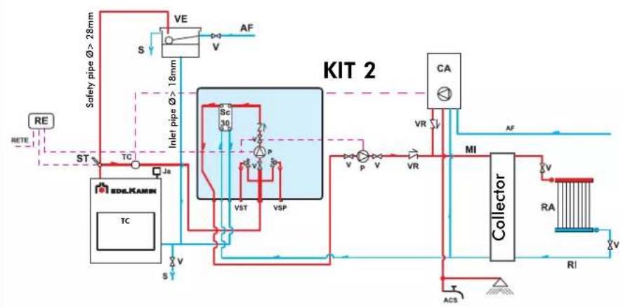
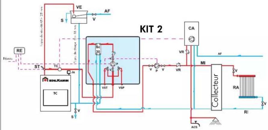
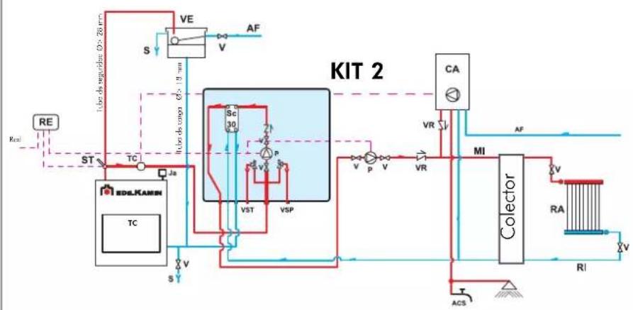
AN EXAMPLE OF A HYDRAULIC SYSTEM FOR A THERMO FIREPLACE THAT DOES NOT PRODUCE HOT SANITARY WATER BUT HAS A WALL MOUNTED BOILER USING KIT 2
KIT 2
flowchart
graph TD
    A["RE"] --> B["ST"]
    B --> C["TC"]
    C --> D["Ja"]
    D --> E["Inlet pipe Ø > 18mm"]
    E --> F["VE"]
    F --> G["S"]
    G --> H["VA"]
    H --> I["AF"]
    I --> J["CA"]
    J --> K["MI"]
    K --> L["Collector"]
    L --> M["RA"]
    M --> N["T"]
    N --> O["ACS"]
    O --> P["RI"]
    P --> Q["V"]
    Q --> R["VA"]
    R --> S["VR"]
    S --> T["VA"]
    T --> U["VA"]
    U --> V["VA"]
    V --> W["VA"]
    W --> X["VA"]
    X --> Y["VA"]
    Y --> Z["VA"]
    Z --> AA["VA"]
    AA --> AB["VA"]
    AB --> AC["VA"]
    AC --> AD["VA"]
    AD --> AE["VA"]
    AE --> AF["VA"]
    AF --> AG["VA"]
    AG --> AH["VA"]
    AH --> AI["VA"]
    AI --> AJ["VA"]
    AJ --> AK["VA"]
    AK --> AL["VA"]
    AL --> AM["VA"]
    AM --> AN["VA"]
    AN --> AO["VA"]
    AO --> AP["VA"]
    AP --> AQ["VA"]
    AQ --> AR["VA"]
    AR --> AS["VA"]
    AS --> AT["VA"]
    AT --> AU["VA"]
    AU --> AV["VA"]
    AV --> AW["VA"]
    AW --> AX["VA"]
    AX --> AY["VA"]
    AY --> AZ["VA"]
AF: Cold Water
CA: Wall Mounted Boiler
MI: System Flow
P: Pump (circulator)
RA: Radiators
RE: Electronic Regulator
RI: System Return
S: Drain
Ja: Automatic Relief Valve
Sc 30: 30-plate Heat Exchanger
ST: Temperature Sensor
TC: Thermo Fireplace
V: Valve
VE: Open Expansion Tank
VR: Check Valve
VSP: 1.5 bar Pressurized Safety Valve
VST: Thermal Relief Valve
NB: insulating mats must be applied so that the components of the kit are well-protected from the heat radiation emitted by the fireplace.
Kit 2 is designed to facilitate the work carried out by the installers. In fact, it consists of all the necessary components for the product to be properly installed.
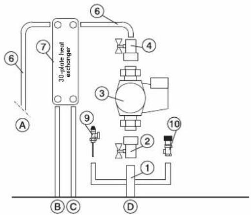
Components KIT 2
Regulator
(included in the kit)
The sales codes are in brackets ( )
1 1" Male-Female Brass Collector
2 1" Ball Valve
3 Circulator with 1½" Fasteners (219660)
4 1" Check Valve (261910)
5 1" Male-Female 3-way Solenoid Valve (143330)
6 Copper Fittings
7 30-plate Heat Exchanger for heat transfer with the gas boiler circuit (216620)
8 20-plate Heat Exchanger for hot sanitary water production (205270)
9 3/4" Thermal Relief Valve (72940)
10 3/4" 1.5 bar Safety Valve (143260)
1 Flow Switch (220830)
12 1/2" Thermometer Well + Sensor (175960)
13 Electronic Regulator (220780)
A 3/4" System Return
B 34 " System Flow
C 3/4" Fireplace Return
D 1" Fireplace Flow
E 1/2" Cold Sanitary Water
F 1/2" Hot Sanitary Water
Electrical Connections
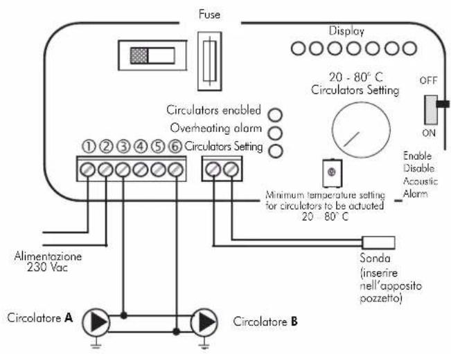
SELECTOR FUNCTIONS
Selector: OFF Everything is switched off
Selector: MAN Driven Circulator
Valve is set
Selector: AUTO Circulator is set
Valve is set
Alarm selection No acoustic signal in the
OFF position
natural_image
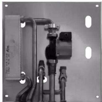
Industrial piping system with valves and a control panel, mounted on a metal frame (no visible text or symbols)KIT 2
code 261890
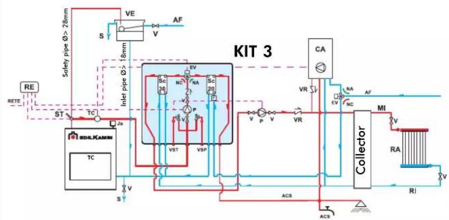
AN EXAMPLE OF A HYDRAULIC SYSTEM FOR A THERMO FIREPLACEITH HOT SANITARY WATER PRODUCTION AND A WALL MOUNTED BOILER
USING
KIT 3
flowchart
graph TD
    A["RE"] --> B["ST"]
    B --> C["TC"]
    C --> D["Ja"]
    D --> E["TC"]
    E --> F["S"]
    F --> G["VE"]
    G --> H["V"]
    H --> I["AF"]
    I --> J["SA"]
    J --> K["CA"]
    K --> L["Collector"]
    L --> M["MI"]
    M --> N["RA"]
    N --> O["RI"]
    O --> P["ACS"]
    P --> Q["T"]
    Q --> R["ACS"]
    R --> S["VA"]
    S --> T["P"]
    T --> U["V"]
    U --> V["P"]
    V --> W["V"]
    W --> X["V"]
    X --> Y["VR"]
    Y --> Z["CA"]
    Z --> AA["Collector"]
    AA --> AB["MI"]
    AB --> AC["RA"]
    AC --> AD["RI"]
    AD --> AE["T"]
    AE --> AF["ACS"]
    AF --> AG["VST"]
    AG --> AH["VSP"]
    AH --> AI["P"]
    AI --> AJ["SC 10"]
    AJ --> AK["NC"]
    AK --> AL["SA 20"]
    AL --> AM["SA 30"]
    AM --> AN["SA 40"]
    AN --> AO["SA 50"]
    AO --> AP["SA 60"]
    AP --> AQ["SA 70"]
    AQ --> AR["SA 80"]
    AR --> AS["SA 90"]
    AS --> AT["SA 100"]
    AT --> AU["SA 110"]
    AU --> AV["SA 120"]
    AV --> AW["SA 130"]
    AW --> AX["SA 140"]
    AX --> AY["SA 150"]
    AY --> AZ["SA 160"]
    AZ --> BA["SA 170"]
    BA --> BB["SA 180"]
    BB --> BC["SA 190"]
    BC --> BD["SA 200"]
    BD --> BE["SA 210"]
    BE --> BF["SA 220"]
    BF --> BG["SA 230"]
    BG --> BH["SA 240"]
    BH --> BI["SA 250"]
    BI --> BJ["SA 260"]
    BJ --> BK["SA 270"]
    BK --> BL["SA 280"]
    BL --> BM["SA 290"]
    BM --> BN["SA 300"]
    BN --> BO["SA 310"]
    BO --> BP["SA 320"]
    BP --> BQ["SA 330"]
    BQ --> BR["SA 340"]
    BR --> BS["SA 350"]
    BS --> BT["SA 360"]
    BT --> BU["SA 370"]
    BU --> BV["SA 380"]
    BV --> BW["SA 390"]
    BW --> BX["SA 400"]
    BX --> BY["SA 410"]
    BY --> BZ["SA 420"]
    BZ --> CA["SA 430"]
    CA --> CB["SA 440"]
    CB --> CC["SA 450"]
    CC --> CD["SA 460"]
    CD --> CE["SA 470"]
    CE --> CF["SA 480"]
    CF --> CG["SA 490"]
    CG --> CH["SA 500"]
    CH --> CI["SA 510"]
    CI --> CJ["SA 520"]
    CJ --> CK["SA 530"]
    CK --> CL["SA 540"]
    CL --> CM["SA 550"]
    CM --> CN["SA 560"]
    CN --> CO["SA 570"]
    CO --> CP["SA 580"]
    CP --> CQ["SA 590"]
    CQ --> CR["SA 600"]
    CR --> CS["SA 610"]
    CS --> CT["SA 620"]
    CT --> CU["SA 630"]
    CU --> CV["SA 640"]
    CV --> CW["SA 650"]
    CW --> CX["SA 660"]
    CX --> CY["SA 670"]
    CY --> CZ["SA 680"]
    CZ --> DA["SA 690"]
    DA --> DB["SA 700"]
    DB --> DC["SA 710"]
    DC --> DD["SA 720"]
    DD --> DE["SA 730"]
    DE --> DF["SA 740"]
    DF --> DG["SA 750"]
    DG --> DH["SA 760"]
    DH --> DI["SA 770"]
    DI --> DJ["SA 780"]
    DJ --> DK["SA 790"]
ACS: Hot Sanitary Water
AF: Cold Water
CA: Wall Mounted Boiler
EV: 3-way Solenoid Valve
F: Flow Switch
MI: System Flow
NA: Normally Open
NC: Normally Closed
P: Pump (circulator)
RA: Radiators
RE: Electronic Regulator
RI: System Return
S: Drain
Sc 20: 20-plate Heat Exchanger
Sc 30: 30-plate Heat Exchanger
TC: Thermo Fireplace
V: Valve
VE: Open Expansion Tank
VR: Check Valve
VSP: 1.5 bar Pressurized Safety Valve
VST: Thermal Relief Valve
Ja: Automatic Relief Valve
Kit 3 is designed to facilitate the work carried out by the installers. In fact, it consists of all the necessary components for the product to be properly installed.
NB: insulating mats must be applied so that the components of the kit are well-protected from the heat radiation emitted by the fireplace.
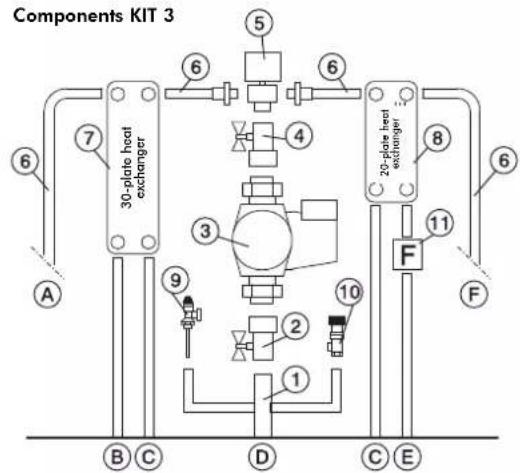
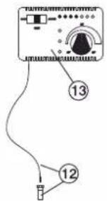
Regulator
(included in the kit)
The sales codes are in brackets ( )
1" Male-Female Brass Collector
1" Ball Valve
2 Circulator with 1½" Fasteners (219660)
1" Check Valve (261910)
1" Male-Female 3-way Solenoid Valve (143330)
Copper Fittings
30-plate Heat Exchanger for heat transfer with
the gas boiler circuit
(216620)
8 20-plate Heat Exchanger for hot sanitary water production (205270)
9 3/4" Thermal Relief Valve (72940)
10 3/4" 1.5 bar Safety Valve (143260)
11 Flow Switch (220830)
12 1/2" Thermometer Well + Sensor (175960)
13 Electronic Regulator (220780)
A 3/4" System Return
B 3/4" System Flow
C 3/4" Fireplace Return
D 1" Fireplace Flow
E 1/2" Cold Sanitary Water
F 1/2" Hot Sanitary Water
Electrical Connections
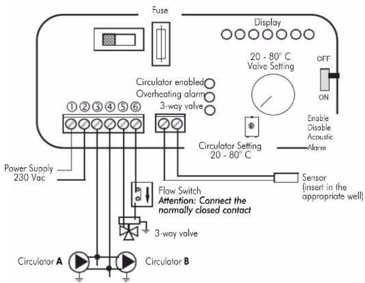
SELECTOR FUNCTIONS
Selector: OFF Everything is switched off
Selector: MAN Driven Circulator
Valve is set
Selector: AUTO Circulator is set
Valve is set
Alarm selection No acoustic signal in the
OFF position
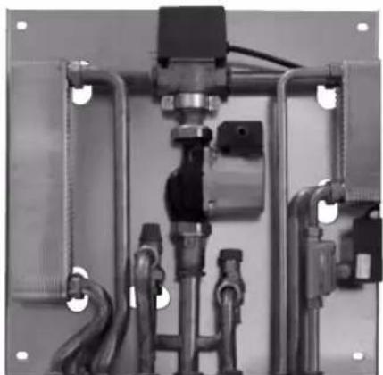
natural_image
Industrial piping system with valves and valves mounted on a metal frame (no visible text or labels)KIT 3
code 261900
THE INLET AND OUTLET PIPES MUST BE CROSSED FOR THE KIT TO FUNCTION PROPERLY
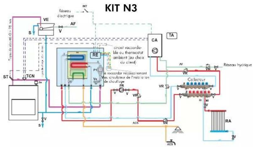
AN EXAMPLE OF A HYDRAULIC SYSTEM FOR A THERMO FIREPLACEITH HOT SANITARY WATER PRODUCTION AND A WALL MOUNTED BOILER
USING KIT N3
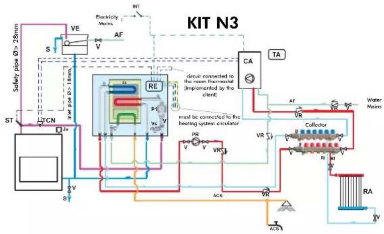
flowchart
graph TD
    A["Safety pipe Ø > 28mm"] --> B["TCN"]
    B --> C["IEC"]
    C --> D["RE"]
    D --> E["CA"]
    E --> F["Collector"]
    F --> G["Water Mains"]
    C --> H["PE"]
    H --> I["PR"]
    I --> J["VR"]
    J --> K["ACS"]
    K --> L["RA"]
    L --> M["ACS"]
    M --> N["VA"]
    style A fill:#f9f,stroke:#333
    style B fill:#ccf,stroke:#333
    style C fill:#cfc,stroke:#333
    style D fill:#fcc,stroke:#333
    style E fill:#cff,stroke:#333
    style F fill:#ffc,stroke:#333
    style G fill:#cfc,stroke:#333
    style H fill:#fcc,stroke:#333
    style I fill:#cfc,stroke:#333
    style J fill:#cfc,stroke:#333
    style K fill:#cfc,stroke:#333
    style L fill:#cfc,stroke:#333
    style M fill:#cfc,stroke:#333
    style N fill:#cfc,stroke:#333
CA: Wall Mounted Boiler
PR: Pump (circulator)
P1: Primary circuit pump
RE: Electronic regulator
TA: Room thermostat
VE: Expansion Tank
Ja: Air refief Valve
V: Intercept valve
VR: Retaining valve
ST: Temperature Sensor
F: Flow switch
Sc: Heat plate exchanger
EV: 3-way solenoid valve
RI: Heating system return
RA: Radiators
MI: Heating system flow
AF: Cold water
ACS: Hot sanitary water
S: Drain
Kit N3 is designed to facilitate the work carried out by the installers. In fact, it consists of all the necessary components for the product to be properly installed.
NB: insulating mats must be applied so that the components of the kit are well-protected from the heat radiation emitted by the fireplace.
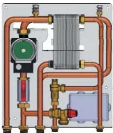
Components KIT N3
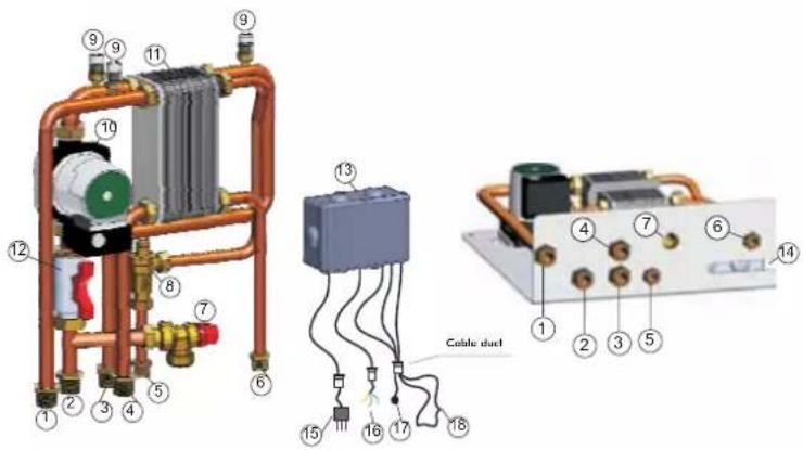
1 Heating system return G 3/4"
2 EDILKAMIN generator flow G 3/4"
3 EDILKAMIN generator return G 3/4"
4 Heating system flow G 3/4"
5 Cold sanitary water inlet G 1/2"
6 Hot water return to the sanitary system G 1/2"
7 Safety valve - temperature and pressure (90 °C - 3bar)
8 Flow Switch
9 Air relief valve G 3/8"
10 EDILKAMIN generator circuit circulator
11 3-way heat exchanger
12 Intercept valve G 1"
13 Electronic regulator with wiring
14 Appropriate aperture for the cable duct to pass through
15 Power cable
16 Cables for the heating system circulator (phase, neutral, earth)
17 Temperature sensor
18 Room thermostat circuit
Electrical Connections
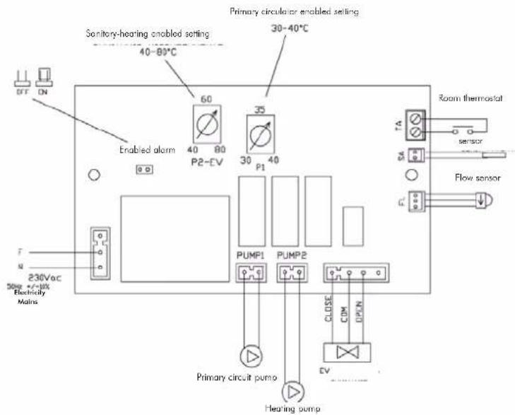
natural_image
Pure mechanical piping diagram without any text, numbers, or symbolsKIT N3
code 627690
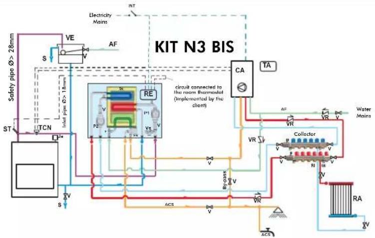
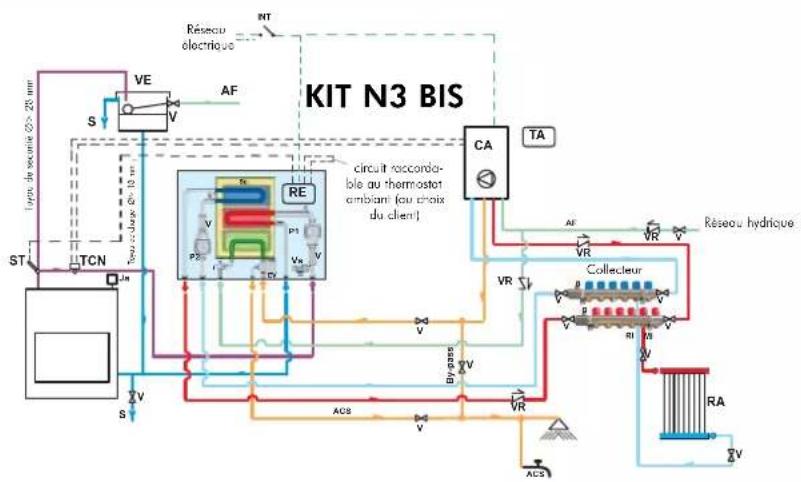
AN EXAMPLE OF A HYDRAULIC SYSTEM FOR A THERMO FIREPLACE WITH HOT SANITARY WATER PRODUCTION AND A WALL MOUNTED BOILER
USING KIT N3 BIS
flowchart
graph TD
    A["Safety pipe Ø> 28mm"] --> B["TCN"]
    B --> C["PTA"]
    C --> D["RE"]
    D --> E["CA"]
    E --> F["TA"]
    F --> G["Water Mains"]
    G --> H["Collector"]
    H --> I["V"]
    H --> J["V"]
    H --> K["V"]
    H --> L["V"]
    H --> M["V"]
    H --> N["V"]
    H --> O["V"]
    H --> P["V"]
    H --> Q["V"]
    H --> R["V"]
    H --> S["V"]
    H --> T["V"]
    H --> U["V"]
    H --> V["V"]
    H --> W["V"]
    H --> X["V"]
    H --> Y["V"]
    H --> Z["V"]
    H --> AA["V"]
    H --> AB["V"]
    H --> AC["V"]
    H --> AD["V"]
    H --> AE["V"]
    H --> AF["V"]
    H --> AG["V"]
    H --> AH["V"]
    H --> AI["V"]
    H --> AJ["V"]
    H --> AK["V"]
    H --> AL["V"]
    H --> AM["V"]
    H --> AN["V"]
    H --> AO["V"]
    H --> AP["V"]
    H --> AQ["V"]
    H --> AR["V"]
    H --> AS["V"]
    H --> AT["V"]
    H --> AU["V"]
    H --> AV["V"]
CA Wall Mounted Boiler
P2 Pump (circulator)
P1 Primary circuit pump
RE Electronic regulator
TA Room Thermostat
VE Expansion Tank
Ja Air Relief Valve
V Intercept valve
VR Retaining valve
ST Temperature Sensor
F Flow switch
Sc Heat Plate Exchanger
EV 3-way Solenoid Valve
RI Heating system return
RA Radiators
MI Heating system flow
AF Cold Water
ACS Hot Sanitary Water
S Drain
INT Main switch
TCN Contact Thermostat
Kit N3 BIS is designed to facilitate the work carried out by the installers. In fact, it consists of all the necessary components for the product to be properly installed.
NB: insulating mats must be applied so that the components of the kit are well-protected from the heat radiation emitted by the fireplace.
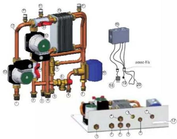
Components KIT N3 BIS
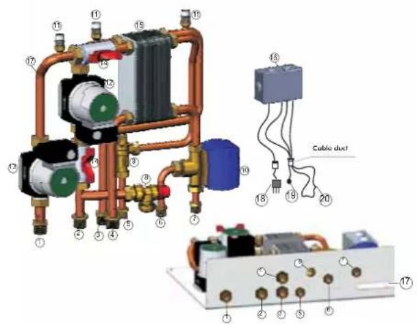
1 Heating system return G 3/4"
2 EDILKAMIN generator flow G 3/4"
3 EDILKAMIN generator return G 3/4"
4 Heating system flow G 3/4"
5 Cold sanitary water inlet G 1/2"
6 Hot water return to the sanitary system G 1/2"
7 Sanitary hot water inlet to the gas boiler G 1/2"
8 Safety valve - temperature and pressure (90 °C - 3bar)
9 Flow Switch
10 3-way deviation solenoid valve
11 Air relief valve G 3/8"
12 EDILKAMIN generator circuit circulator
13 Heating system circuit circulator
14 Intercept valve G 1"
15 3-way heat exchanger
16 Electronic regulator with wiring
17 Appropriate aperture for the cable duct to pass through
18 Power cable
19 Temperature sensor
20 Room thermostat circuit
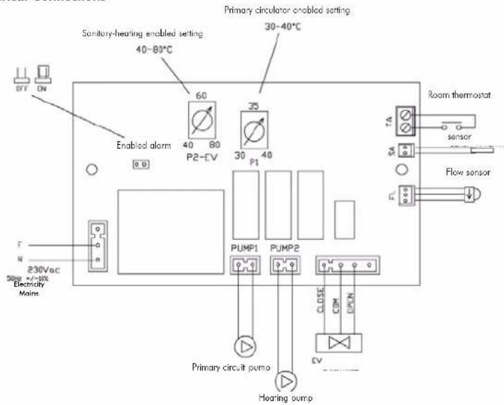
Electrical Connections
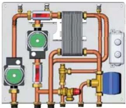
natural_image
Pure electrical circuit lines without any symbolsKIT N3 BIS
code 627860
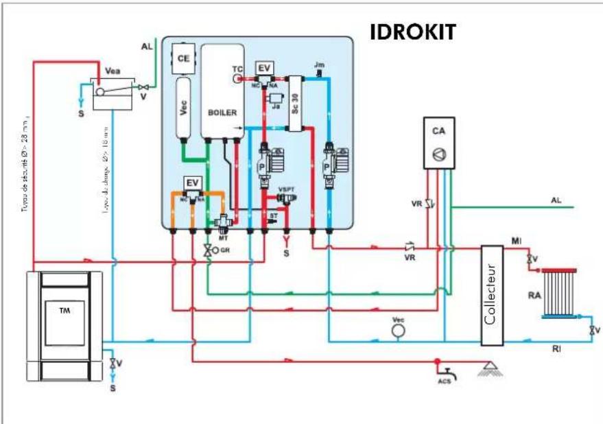
AN EXAMPLE OF A HYDRAULIC SYSTEM FOR A THERMO FIREPLACE THAT PRODUCES AND STORES HOT SANITARY WATER AND HAS A WALL MOUNTED BOILER
USING IDROKIT
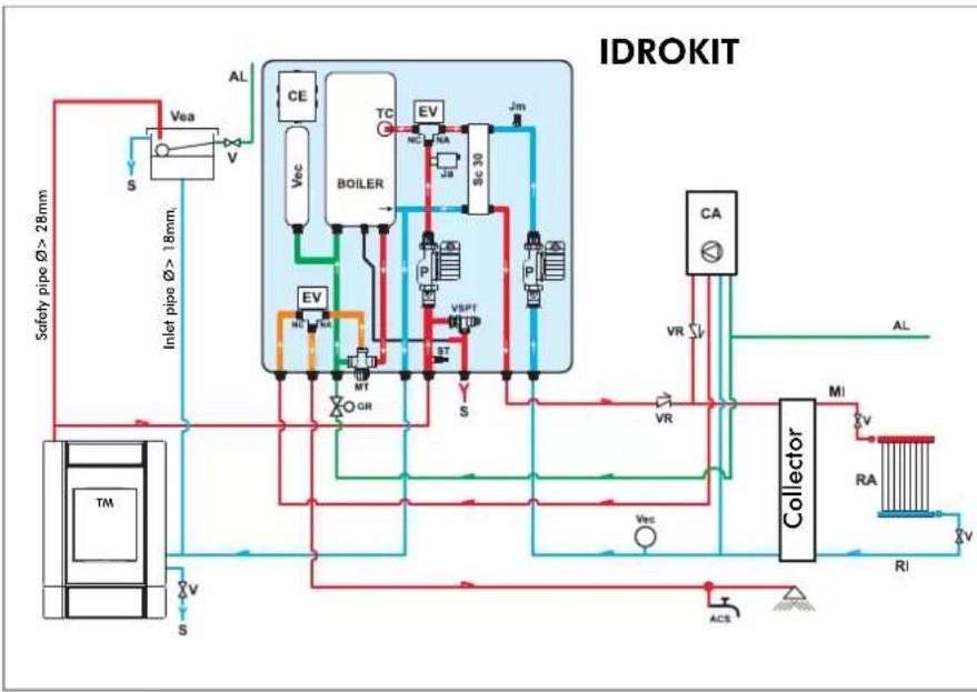
flowchart
graph TD
    A["Safety pipe Ø > 28mm"] --> B["Vea"]
    B --> C["Vea"]
    C --> D["V"]
    D --> E["S"]
    E --> F["Inlet pipe Ø > 18mm"]
    F --> G["MT"]
    G --> H["GEV"]
    H --> I["BOILER"]
    I --> J["TC"]
    J --> K["EV"]
    K --> L["SC 30"]
    L --> M["Jm"]
    M --> N["P"]
    N --> O["P"]
    O --> P["VSPT"]
    P --> Q["BT"]
    Q --> R["S"]
    R --> S["ACS"]
    S --> T["Collector"]
    T --> U["MI"]
    U --> V["RA"]
    V --> W["RI"]
    W --> X["V"]
    X --> Y["S"]
    Y --> Z["V"]
    Z --> A
    style A fill:#f9f,stroke:#333
    style T fill:#ccf,stroke:#333
ACS: Hot Sanitary Water
AF: Cold Water
AL: Water Mains Supply
C: Filling/Top-Up Section
CE: Electronic Panel
EV: 3-way Solenoid Valve
NA: Normally Open
NC: Normally Closed
GR: Pressure Reducer
Ja: Automatic Relief Valve
Jm: Manual Relief Valve
MI: System Flow
MT: Thermostatic Mixer
P: Pump (circulator)
RA: Radiators
RI: System Return
S: Drain
SC30: 30-plate Heat Exchanger
ST: Temperature Sensor
TC: Contact Thermostat
TM: Thermo Fireplace
V: Ball Valve
Vea: Open Expansion Tank
Vec: Closed Expansion Tank
VR: Check Valve
VSPT: Safety Pressure and Temperature Valve
VCA: Boiler
IDROKIT is designed to facilitate the work carried out by the installers. In fact, it consists of all the necessary components for the product to be properly installed.
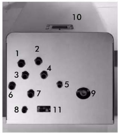
1 heating return
2 gas boiler hot sanitary water
3 thermo fireplace flow
4 drain
5 hot sanitary water
6 thermo fireplace return
7 heating flow
8 water mains
9 thermostatic mixer setting
10 synoptic panel
11 auxiliary socket for a room thermostat

SYSTEM FOR A CLOSED TANKINSTALLATION
(VALID ONLY FOR IDRO 50/CS)
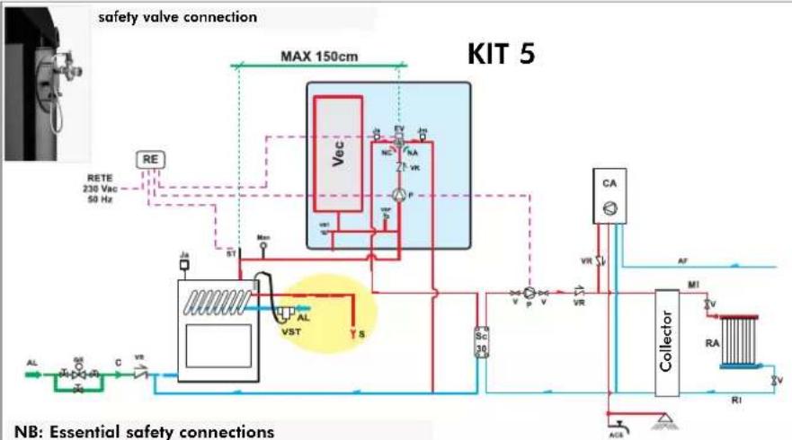
AN EXAMPLE OF A HYDRAULIC SYSTEM FOR A THERMO FIREPLACE - ONLY HEATING
USING KIT 5
flowchart
graph TD
    A["RETE 230 Vac 50 Hz"] --> B["Max 150cm"]
    B --> C["VST"]
    C --> D["Spec"]
    D --> E["Collector"]
    E --> F["RA"]
    F --> G["RI"]
    G --> H["ACR"]
    H --> I["SC 30"]
    I --> J["VR"]
    J --> K["CA"]
    K --> L["AF"]
    L --> M["M1"]
    M --> N["VA"]
    N --> O["RA"]
    O --> P["RI"]
    P --> Q["ACR"]
    Q --> R["SC 30"]
    R --> S["VR"]
    S --> T["CA"]
    T --> U["AF"]
    U --> V["M1"]
    V --> W["RA"]
    W --> X["RI"]
    X --> Y["ACR"]
AL: Water Mains Supply
C: Filling/Top-Up Section
EV: 3-way Solenoid Valve
NA: Normally Open
NC: Normally Closed
GR: Filling unit
Ja: Automatic Relief Valve
Jm: Manual Relief Valve
MAN: Manometer
MI: System Flow
P: Pump (circulator)
RA: Radiators
RE: Electronic Regulator
RI: System Return
S: Drain
ST: Temperature Sensor
V: Ball Valve
Vec: Closed Expansion Tank
VR: Check Valve
VSP: Pressurised Safety Valve
VST: Thermal Relief Valve
Kit 5 is designed to facilitate the work carried out by the installers. In fact, it consists of all the necessary components for the product to be properly installed.
NB: insulating mats must be applied so that the components of the kit are well protected from the heat radiation emitted by the fireplace.
Components KIT 5
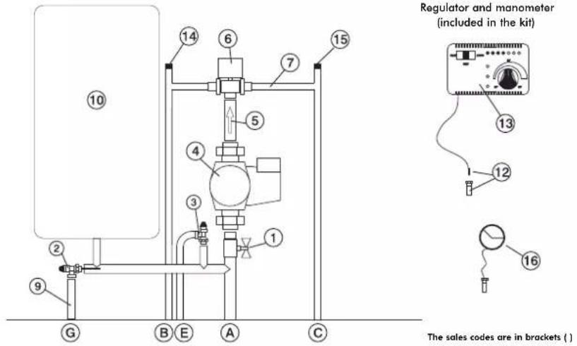
1 1" Ball Valve
2 Thermal Relief Valve (72940)
3 Pressure Relief Valve (284220)
4 Circulator (219660)
5 Fittings with 1' Check Valve (284180)
6 3/4" Male 3-way Solenoid Valve (283690)
7 Fittings
9 Temperature Relief Valve Nozzle
10 Closed Expansion Tank (283680)
12 1/2" Thermometer Well + Sensor (175960)
13 Electronic Regulator (220780)
14 3/8" Automatic Relief Valve (284150)
15 1/4" Manual Relief Valve (284)70)
16 Manometer (269590)
A Fireplace Flow
B System return
c Fireplace Return
E Pressure Relief Valve
G Temperature Relief Valve
Electrical Connections
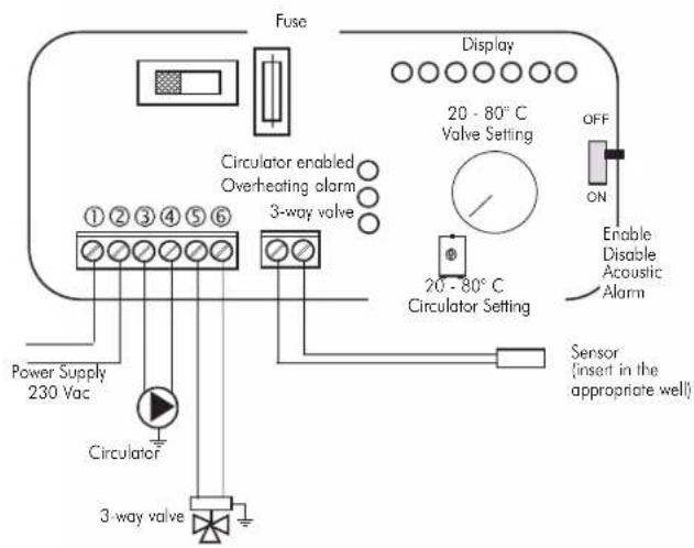
SELECTOR FUNCTIONS
Selector: OFF Everything is switched off
Selector: MAN Driven Circulator
Valve is set
Selector: AUTO Circulator is set
Valve is set
Alarm selection No acoustic signal in the
OFF position
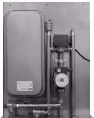
natural_image
Industrial pressure pump unit with control panel and piping (no visible text or symbols)KIT 5
code 280590
SYSTEM FOR A CLOSED TANKINSTALLATION
(VALID ONLY FOR IDRO 50/CS)
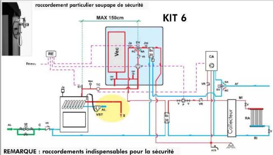
AN EXAMPLE OF A HYDRAULIC SYSTEM FOR A THERMO FIREPLACE WITH HOT SANITARY WATER PRODUCTION
USING KIT 6
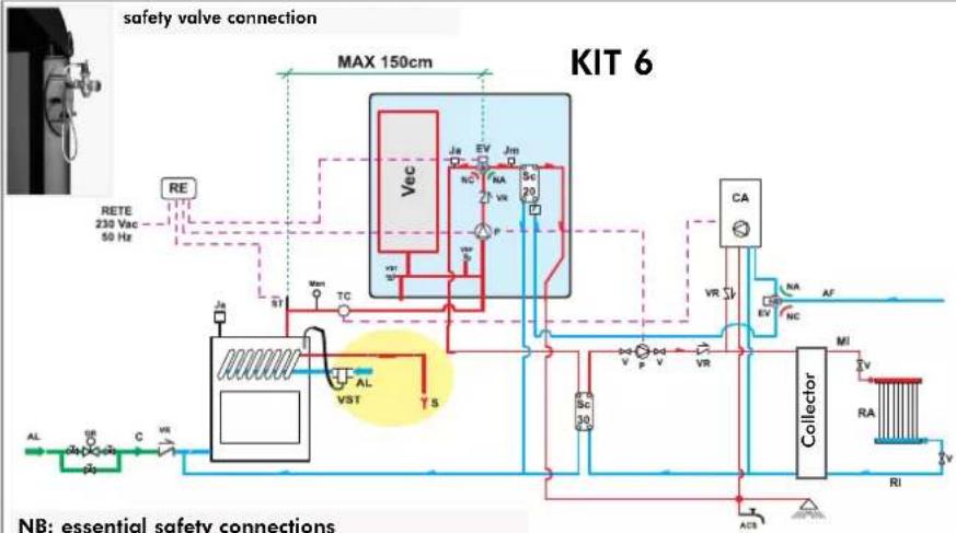
flowchart
graph TD
    A["RETE 230 Vac 50 Hz"] --> B["Max 150cm"]
    B --> C["Vec"]
    C --> D["VA"]
    D --> E["SC 20"]
    E --> F["Collector"]
    F --> G["RA"]
    G --> H["RI"]
    H --> I["MI"]
    I --> J["Collector"]
    J --> K["RA"]
    K --> L["MI"]
    L --> M["Collector"]
    M --> N["RA"]
    N --> O["MI"]
    O --> P["Collector"]
    P --> Q["RA"]
    Q --> R["MI"]
    R --> S["Collector"]
    S --> T["RA"]
    T --> U["MI"]
    U --> V["Collector"]
    V --> W["RA"]
    W --> X["MI"]
    X --> Y["Collector"]
    Y --> Z["RA"]
    Z --> AA["MI"]
    AA --> AB["Collector"]
    AB --> AC["RA"]
    AC --> AD["MI"]
    AD --> AE["Collector"]
    AE --> AF["RA"]
    AF --> AG["MI"]
ACS: Hot Sanitary Water
AF: Cold Water
AL: Water Mains Supply
C: Filling/Top-Up Section
EV: 3-way Solenoid Valve
NA: Normally Open
NC: Normally Closed
F: Flow Switch
GR: Filling unit
Ja: Automatic Relief Valve
Jm: Manual Relief Valve
MAN: Manometer
MI: System Flow
P: Pump (circulator)
RA: Radiators
RE: Electronic Regulator
RI: System Return
S: Drain
SC: Plate Exchanger
ST: Temperature Sensor
V: Ball Valve
Vec: Closed Expansion Tank
VR: Check Valve
VSP: Pressurised Safety Valve
VST: Thermal Relief Valve
Kit 6 is designed to facilitate the work carried out by the installers. In fact, it consists of all the necessary components for the product to be properly installed.
NB: insulating mats must be applied so that the components of the kit are well protected from the heat radiation emitted by the fireplace.
Componenti KIT 6
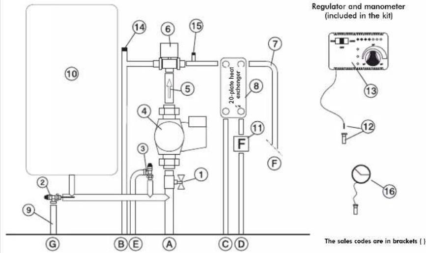
1 1" Ball Valve
2 Thermal Relief Valve (72940)
3 Pressure Relief Valve (284220)
4 Circulator (219660)
5 Fittings with 1' Check Valve (284180)
6 3/4" Male 3-way Solenoid Valve (283690)
7 Fittings
8 20-plate Heat Exchanger for hot sanitary water production (284300)
9 Temperature Relief Valve Nozzle
10 Closed Expansion Tank (283680)
11 Flow Switch (220830)
12 1/2" Thermometer Well + Sensor (175960)
13 Electronic Regulator (220780)
14 3/8" Automatic Relief Valve (284150)
15 1/4" Manual Relief Valve (284170)
16 Manometer (269590)
A Fireplace Return
B System Return
C Fireplace Return
D Cold Sanitary Water
E Pressure Relief Valve
F Hot Sanitary Water
G Temperature Relief Valve
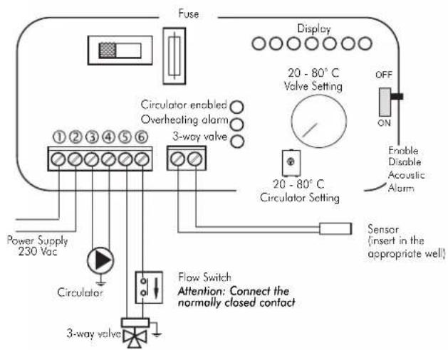
Electrical Connections
SELECTOR FUNCTIONS
Selector: OFF Everything is switched off
Selector: MAN Driven Circulator
Valve is set
Selector: AUTO Circulator is set
Valve is set
Alarm selection No acoustic signal in the
OFF position
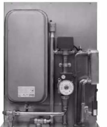
natural_image
Industrial equipment setup with pressure vessel, tubing, and control panel (no visible text or symbols)KIT 6
code 280600
electronic regulator
IMPORTANT ADVICE REGARDING THE INSTALLATION
The connections, commissioning and verification of proper operation of the fireplace must be carried out by qualified personnel, who can implement all connections in accordance with the laws in force, particularly with Italian Law No. 46/90, apart from complying with these instructions.
Compliance with regulations regarding the earth connection is fundamental for the safety of people.
It is obligatory to install a differential circuit breaker switch before the device and the entire electrical circuit of the thermo fireplace. It is also obligatory to connect the pump, valve and metal parts of the thermo fireplace to an earthing system.
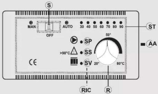
LEGEND
AA acoustic alarm switch
R way valve opening setting (KITS 1-3-5-6)
R circulators operation setting (KIT 2)
RIC internal pump setting
S MAN-OFF-AUTO selector
SP pump light
SS overheating light
ST temperature scale
SV 3-way valves light (KITS 1-3-5-6)
SV circulators setting (KIT 2)
fig. M
| Technical Data | |
| Power Supply (+15 – 10%) Vac 230 | |
| Degree of protection IP 40 | |
| Min/Max Room Temperature °C 0 to+50 | |
| Sensor range m 1,2 | |
| Thermometer °C 30 to 90 | |
| Maximum contact rating of the circulator W 400 | |
| Maximum contact rating of the 3-way valve W 250 | |
| Fuse mA 500 |
The electric control regulator allows you to monitor the operating conditions and is equipped with:
- MAN-OFF-AUTO selector (S)
- temperature scale (ST)
- acoustic alarm (AA)
- 3-way valve opening setting (R) (KIT1-3)
- circulators operation setting (R) (KIT2)
- internal pump setting (RIC)
- 3-way valve light (SV) (KIT1-KIT3)
- circulators setting light (SV) (KIT2)
- overheating pump (SS)
- pump light (SP)
Operation
- Control device:
- Thermometer
- Protection device
(acoustic alarm system):
• Acoustic alarm (AA)
• Overheating alarm (SS)
This system intervenes when the water temperature exceeds 90^ C and warns the user to stop adding fuel.
The acoustic alarm can be disabled from the switch (AA).
However, the alarm remains enabled by means of the
overheating light (SS).
To restore the initial settings, the switch (AA) must be enabled after the water temperature in the thermo fireplace has cooled down.
- Power supply device
(circulation system):
• MAN-OFF-AUTO selector (S)
- Pump light (SP)
The pump remains on when in manual mode and off when in
OFF mode. When in AUTO mode, the pump is activated by the system when the desired temperature is reached, by means of the internal setting (RIC), which ranges from 20 to 80^ (this is pre-set at 20^ ).
- Operation device (setting system):
• 3-way valve opening setting (R)
•3-way valve operating light (SV)
When the fluid reaches the temperature set through the regulator, the 3-way valve diverts the fluid to the radiators and the operating light (SV) goes on.
When the temperature of the fluid drops below the set value, the system opens the electrical circuit and the 3-way valve bypasses the fluid directly to the thermo fireplace.
Attention:
During normal operation check that the warning lights (SV) and (SP) are lit.
Positioning
The electronic regulator must be installed close to the thermo fireplace.
The sensor of the operation, protection and control devices must be placed directly on the thermo fireplace or at most on the flow pipe, no more than 5 cm away from the thermo fireplace and in any case before any intercepting device.
The sensor must be immersed in the well.
Installation
Follow this procedure to install the electronic regulator correctly: loosen the fastening screw, remove the cover and fasten it in place against the wall with the dowels supplied.
Then make the connections, paying utmost attention to the wiring diagram and pass the wires through ducts that are in conformity with the regulations in force. Put the cover back in place and tighten the screw.
The power supply must be disconnected from the mains and the AUTO-OFF-MAN selector (S) must be in the OFF position when all these operations are carried out.
Connect the brown wire (phase) and blue wire (neutral) of the 3-way
Valve, respectively, to terminals 5 and 6 of the regulator.
Connect the yellow/green wire to the earth.
Follow the assembly instructions contained in the package to connect the regulator to the system properly.
ELECTRONIC REGULATOR (Optional)
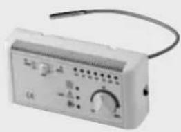
This lets you monitor the operating conditions and is equipped with:
- MAN-OFF-AUTO selector
- temperature scale
- acoustic alarm
- 3-way valve opening setting
- internal pump setting
- pump light
- 3-way valve light
- overheating light
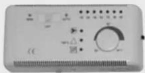
natural_image
Front view of a control panel with display and rotary dial (no visible text or symbols)Electronic Regulator (220780)
HEAT EXCHANGER FOR SANITARY WATER (Optional)
This is a very simple and inexpensive device with guaranteed performance that produces 13-14 litres of hot water per minute.
It is easily installed on the flow pipe to the radiators, in the most suitable position according to the layout of the system.
Alternatively, it can be purchased as part of installation KITS 1/3/6 offered by Italiana CAmini. This has the great advantage of being removed for maintenance or replacement without affecting the thermo fireplace.
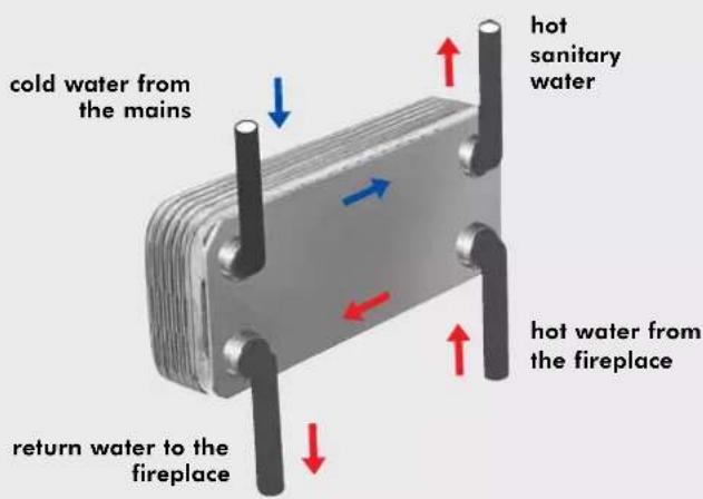
The electronic regulator and the plate exchanger are included in the installation KITS (supplied as optional extras)
natural_image
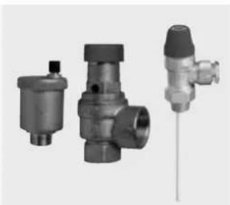
Three industrial valve components shown from different angles (no text or labels visible)Valves Kit (421600) consisting of: automatic air relief valve, 1.5 bar safety valve, 90 °C thermal relief valve
natural_image
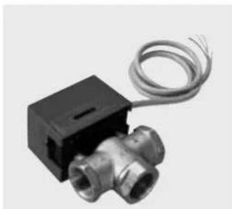
Close-up of a metallic T-shaped valve with coiled cable, no visible text or symbols1 " 3-way valve (143330) to set the water flow to the system
natural_image
White electronic device with control panel and wiring (no visible text or symbols)Electronic Regulator (220780)
natural_image
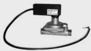
Mechanical sensor device with black housing and coiled cable (no visible text or symbols)Flow Switch (220830)
natural_image
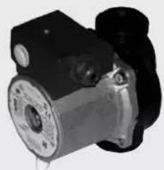
Close-up of a mechanical pump or motor component (no visible text or symbols)Circulator UPS 25-50 code 219660 UPS 25-60 code 238270
natural_image
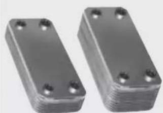
Two metallic rectangular electronic components with four mounting holes (no text or symbols visible)20-plate Heat 30-plate Heat Exchanger for sanitary water (262570) Exchanger for sanitary water (216620)
natural_image
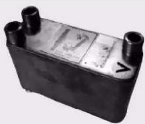
Black rectangular electronic component with two cylindrical ports and a labeled section (no readable text or symbols)Exchanger 3-way code 627780
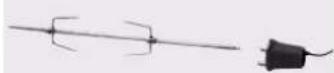
Roaster
Idro 50-70 cod. 234560
Idro 100 cod. 236710
Madame, Monsieur,
natural_image
Technical diagram of a portable electrical enclosure with labeled components and a close-up view of its internal structure (no text or symbols present)natural_image
Technical line drawing of a mechanical assembly with no visible text or symbols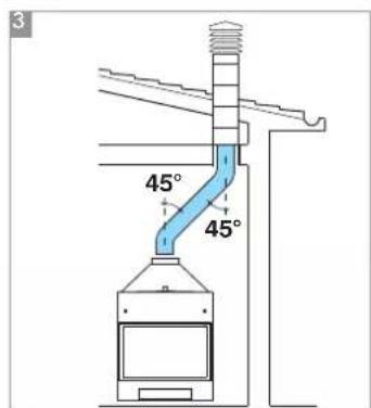
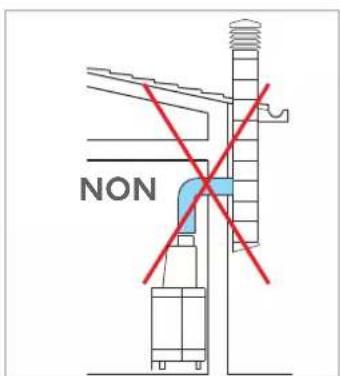
fig.A
INSTRUCTIONS POUR L'INSTALLATION ET L'UTILISATION
natural_image
Mechanical assembly with pipes and housing components (no visible text or symbols)KIT 1
code 261880
EXEMPLE DE SYSTÈME HYDRAULIQUE POUR THERMOCHEMINÉE SANS PRODUCTION D'EAU CHAUDE SANITAIRE + CHAUDIÈRE MURALE
AVEC UTILISATION DU
KIT 2
flowchart
graph TD
    RE["RE"] --> ST["ST"]
    ST --> TC["TC"]
    TC --> Ja["Ja"]
    Ja --> S["S"]
    S --> VE["VE"]
    VE --> V["AF"]
    V --> V
    V --> VSP["VSP"]
    VSP --> Sc["Sc 30"]
    Sc --> VST["VST"]
    VST --> V
    VSP --> VSP
    VSP --> VSP
    VSP --> V
    VSP --> VSP
    VSP --> CA["CA"]
    CA --> VR["VR"]
    VR --> MI["MI"]
    MI --> Collecteur["Collecteur"]
    Collecteur --> RA["RA"]
    Collecteur --> RI["RI"]
    Collecteur --> AV["AV"]
    AV --> T["ACS"]
    T --> V
    V --> VSP
    VSP --> VST
    VST --> V
    VSP --> VSP
    VSP --> VSP
    VSP --> V
    VSP --> VSP
    style KIT2 fill:#f9f,stroke:#333,stroke-width:2px
AF: Eau Froide
CA: Chaudière murale
natural_image
Industrial piping system with valves and a control panel, mounted on a metal frame (no visible text or symbols)KIT 2
code 261890
EXEMPLE DE SYSTÈME HYDRAULIQUE POUR THERMOCHEMINÉE AVEC PRODUCTION D'EAU CHAUDE SANITAIRE + CHAUDIÈRE MURALE
AVEC UTILISATION DU
KIT 3
flowchart
graph TD
    A["RE"] --> B["ST"]
    B --> C["TC"]
    C --> D["Ja"]
    D --> E["SC 30"]
    E --> F["VST"]
    F --> G["VSP"]
    G --> H["ACS"]
    H --> I["ACS"]
    I --> J["Collecteur"]
    J --> K["MI"]
    K --> L["RA"]
    L --> M["RI"]
    M --> N["VA"]
    N --> O["VA"]
    O --> P["VA"]
    P --> Q["VA"]
    Q --> R["VA"]
    R --> S["VA"]
    S --> T["VA"]
    T --> U["VA"]
    U --> V["VA"]
    V --> W["VA"]
    W --> X["VA"]
    X --> Y["VA"]
    Y --> Z["VA"]
    Z --> AA["VA"]
    AA --> AB["VA"]
    AB --> AC["VA"]
    AC --> AD["VA"]
    AD --> AE["VA"]
    AE --> AF["VA"]
    AF --> AG["VA"]
    AG --> AH["VA"]
    AH --> AI["VA"]
    AI --> AJ["VA"]
    AJ --> AK["VA"]
    AK --> AL["VA"]
    AL --> AM["VA"]
    AM --> AN["VA"]
    AN --> AO["VA"]
    AO --> AP["VA"]
    AP --> AQ["VA"]
    AQ --> AR["VA"]
    AR --> AS["VA"]
    AS --> AT["VA"]
    AT --> AU["VA"]
    AU --> AV["VA"]
    AV --> AW["VA"]
    AW --> AX["VA"]
    AX --> AY["VA"]
    AY --> AZ["VA"]
    AZ --> BA["VA"]
    BA --> BB["VA"]
    BB --> BC["VA"]
    BC --> BD["VA"]
    BD --> BE["VA"]
    BE --> BF["VA"]
    BF --> BG["VA"]
    BG --> BH["VA"]
    BH --> BI["VA"]
    BI --> BJ["VA"]
    BJ --> BK["VA"]
    BK --> BL["VA"]
    BL --> BM["VA"]
    BM --> BN["VA"]
    BN --> BO["VA"]
    BO --> BP["VA"]
    BP --> BQ["VA"]
    BQ --> BR["VA"]
    BR --> BS["VA"]
    BS --> BT["VA"]
    BT --> BU["VA"]
    BU --> BV["VA"]
    BV --> BW["VA"]
    BW --> BX["VA"]
    BX --> BY["VA"]
    BY --> BZ["VA"]
CA: Chaudière murale
natural_image
Industrial piping system with valves and valves mounted on a metal frame (no visible text or labels)KIT 3
code 261900
POUR UN FONCTIONNEMENT CORRECT, IL FAUT CROISER LES TUYAUX D'ALIMENTATION ET DE RETOUR
EXEMPLE DE SYSTÈME HYDRAULIQUE POUR THERMOCHEMINÉE AVEC PRODUCTION D'EAU CHAUDE SANITAIRE + CHAUDIÈRE MURALE
AVEC UTILISATION DU
KIT N3
flowchart
graph TD
    A["Top qu de desiril G > 28 km"] --> B["VE"]
    B --> C["S"]
    C --> D["TCN"]
    D --> E["ST"]
    E --> F["VA"]
    F --> G["RE"]
    G --> H["CA"]
    H --> I["TA"]
    I --> J["RA"]
    J --> K["V"]
    K --> L["ACS"]
    L --> M["Collecteur"]
    M --> N["VR"]
    N --> O["VA"]
    O --> P["VA"]
    P --> Q["VA"]
    Q --> R["VA"]
    R --> S["VA"]
    S --> T["VA"]
    T --> U["VA"]
    U --> V["VA"]
    V --> W["VA"]
    W --> X["VA"]
    X --> Y["VA"]
    Y --> Z["VA"]
    Z --> AA["VA"]
    AA --> AB["VA"]
    AB --> AC["VA"]
    AC --> AD["VA"]
    AD --> AE["VA"]
    AE --> AF["VA"]
    AF --> AG["VA"]
    AG --> AH["VA"]
    AH --> AI["VA"]
    AI --> AJ["VA"]
    AJ --> AK["VA"]
    AK --> AL["VA"]
    AL --> AM["VA"]
    AM --> AN["VA"]
    AN --> AO["VA"]
    AO --> AP["VA"]
    AP --> AQ["VA"]
    AQ --> AR["VA"]
    AR --> AS["VA"]
    AS --> AT["VA"]
    AT --> AU["VA"]
    AU --> AV["VA"]
    AV --> AW["VA"]
    AW --> AX["VA"]
    AX --> AY["VA"]
    AY --> AZ["VA"]
    AZ --> BA["VA"]
    BA --> BB["VA"]
    BB --> BC["VA"]
    BC --> BD["VA"]
    BD --> BE["VA"]
    BE --> BF["VA"]
    BF --> BG["VA"]
    BG --> BH["VA"]
    BH --> BI["VA"]
    BI --> BJ["VA"]
    BJ --> BK["VA"]
    BK --> BL["VA"]
    BL --> BM["VA"]
    BM --> BN["VA"]
    BN --> BO["VA"]
    BO --> BP["VA"]
    BP --> BQ["VA"]
    BQ --> BR["VA"]
    BR --> BS["VA"]
    BS --> BT["VA"]
    BT --> BU["VA"]
    BU --> BV["VA"]
    BV --> BW["VA"]
    BW --> BX["VA"]
    BX --> BY["VA"]
    BY --> BZ["VA"]
CA: Chaudière murale
natural_image
Pure electrical circuit lines without any symbolsKIT N3
code 627690
EXEMPLE DE SYSTÈME HYDRAULIQUE POUR THERMOCHEMINÉE AVEC PRODUCTION D'EAU CHAUDE SANITAIRE + CHAUDIÈRE MURALE
AVEC UTILISATION DU
KIT N3 BIS
flowchart
graph TD
    A["Input"] --> B["TS"]
    B --> C["TCN"]
    C --> D["VE"]
    D --> E["S"]
    E --> F["Output"]
    G["Reservoir électrique"] --> H["NT"]
    H --> I["CA"]
    I --> J["TA"]
    J --> K["VR"]
    K --> L["Collecteur"]
    L --> M["RA"]
    M --> N["VA"]
    N --> O["ACS"]
    O --> P["V"]
    P --> Q["BYBASS"]
    Q --> R["V"]
    R --> S["ACS"]
    S --> T["V"]
    T --> U["VA"]
    U --> V["BYBASS"]
    V --> W["V"]
    W --> X["VA"]
    X --> Y["BYBASS"]
    Y --> Z["V"]
    Z --> AA["VA"]
    AA --> AB["BYBASS"]
    AB --> AC["V"]
    AC --> AD["VA"]
    AD --> AE["BYBASS"]
    AE --> AF["V"]
    AF --> AG["VA"]
    AG --> AH["BYBASS"]
    AH --> AI["V"]
    AI --> AJ["VA"]
    AJ --> AK["BYBASS"]
    AK --> AL["V"]
    AL --> AM["VA"]
    AM --> AN["BYBASS"]
    AN --> AO["V"]
    AO --> AP["VA"]
    AP --> AQ["BYBASS"]
    AQ --> AR["V"]
    AR --> AS["VA"]
    AS --> AT["BYBASS"]
    AT --> AU["V"]
    AU --> AV["VA"]
    AV --> AW["BYBASS"]
    AW --> AX["V"]
    AX --> AY["VA"]
    AY --> AZ["BYBASS"]
CA Chaudière murale
Composants KIT N3 BIS
natural_image
Pure electrical circuit lines without any symbolsKIT N3 BIS
code 627860
flowchart
graph TD
    A["Topso de scrités 01-23 mm"] --> B["VEA"]
    B --> C["S"]
    C --> D["V"]
    D --> E["Boiler"]
    E --> F["TC"]
    F --> G["EV"]
    G --> H["SC 30"]
    H --> I["Jm"]
    I --> J["P"]
    J --> K["P"]
    K --> L["VA"]
    L --> M["CA"]
    M --> N["Collecteur"]
    N --> O["MI"]
    O --> P["RA"]
    P --> Q["RI"]
    Q --> R["ACS"]
    R --> S["Accumulate Valve"]
    S --> T["Valve"]
    T --> U["Valve"]
    U --> V["Valve"]
    V --> W["Valve"]
    W --> X["Valve"]
    X --> Y["Valve"]
    Y --> Z["Valve"]
    Z --> AA["Valve"]
    AA --> AB["Valve"]
    AB --> AC["Valve"]
    AC --> AD["Valve"]
    AD --> AE["Valve"]
    AE --> AF["Valve"]
    AF --> AG["Valve"]
    AG --> AH["Valve"]
    AH --> AI["Valve"]
    AI --> AJ["Valve"]
    AJ --> AK["Valve"]
    AK --> AL["Valve"]
    AL --> AM["Valve"]
    AM --> AN["Valve"]
    AN --> AO["Valve"]
    AO --> AP["Valve"]
    AP --> AQ["Valve"]
    AQ --> AR["Valve"]
    AR --> AS["Valve"]
    AS --> AT["Valve"]
    AT --> AU["Valve"]
    AU --> AV["Valve"]
C: Charge/ Compensation
C: Charge/Compensation
natural_image
Industrial equipment setup with pressure regulator and piping (no visible text or symbols)SYSTÈME POUR INSTALLATION À VASE FERMÉ
(VALABLE UNIQUEMENT POUR IDRO 50/CS)
EXEMPLE DE SYSTÈME HYDRAULIQUE POUR THERMOCHEMINÉE AVEC PRODUCTION D'EAU CHAUDE SANITAIRE
AVEC UTILISATION DU
KIT 6
flowchart
graph TD
    A["RE"] --> B["Valve"]
    B --> C["VA"]
    C --> D["Collecteur"]
    D --> E["RA"]
    E --> F["MI"]
    F --> G["VA"]
    G --> H["VA"]
    H --> I["VA"]
    I --> J["VA"]
    J --> K["VA"]
    K --> L["VA"]
    L --> M["VA"]
    M --> N["VA"]
    N --> O["VA"]
    O --> P["VA"]
    P --> Q["VA"]
    Q --> R["VA"]
    R --> S["VA"]
    S --> T["VA"]
    T --> U["VA"]
    U --> V["VA"]
    V --> W["VA"]
    W --> X["VA"]
    X --> Y["VA"]
    Y --> Z["VA"]
    Z --> AA["VA"]
    AA --> AB["VA"]
    AB --> AC["VA"]
    AC --> AD["VA"]
    AD --> AE["VA"]
    AE --> AF["VA"]
    AF --> AG["VA"]
    AG --> AH["VA"]
    AH --> AI["VA"]
    AI --> AJ["VA"]
    AJ --> AK["VA"]
    AK --> AL["VA"]
    AL --> AM["VA"]
    AM --> AN["VA"]
    AN --> AO["VA"]
    AO --> AP["VA"]
    AP --> AQ["VA"]
    AQ --> AR["VA"]
    AR --> AS["VA"]
    AS --> AT["VA"]
    AT --> AU["VA"]
    AU --> AV["VA"]
    AV --> AW["VA"]
    AW --> AX["VA"]
    AX --> AY["VA"]
    AY --> AZ["VA"]
    AZ --> BA["VA"]
    BA --> BB["VA"]
    BB --> BC["VA"]
    BC --> BD["VA"]
    BD --> BE["VA"]
    BE --> BF["VA"]
    BF --> BG["VA"]
    BG --> BH["VA"]
    BH --> BI["VA"]
    BI --> BJ["VA"]
    BJ --> BK["VA"]
    BK --> BL["VA"]
    BL --> BM["VA"]
    BM --> BN["VA"]
    BN --> BO["VA"]
    BO --> BP["VA"]
    BP --> BQ["VA"]
    BQ --> BR["VA"]
    BR --> BS["VA"]
    BS --> BT["VA"]
    BT --> BU["VA"]
    BU --> BV["VA"]
    BV --> BW["VA"]
    BW --> BX["VA"]
    BX --> BY["VA"]
    BY --> BZ["VA"]
ACS: Eau Choude Sanitaire
AF: Eau Froide
C: Charge/ Compensation
natural_image
Industrial equipment setup with pressure vessel, tubing, and control panel (no visible text or symbols)KIT 6
code 280600
SS voyant surchauffe
natural_image
Front view of a white electronic device with control panel and indicator lights (no visible text or symbols)natural_image
Three industrial valve components shown from different angles (no text or labels visible)natural_image
Close-up of a metallic T-shaped valve with coiled cable, no visible text or symbolsnatural_image
Exterior view of a handheld electronic device with a coiled cable and control panel (no visible text or symbols)natural_image
Mechanical pressure sensor device with coiled cable and terminal block (no visible text or symbols)Fluxostat (220830)
natural_image
Mechanical component with metallic shaft and mounting holes (no visible text or symbols)Circulateur UPS 25-50 code 219660 UPS 25-60 code 238270
natural_image
Two metallic rectangular electronic components with four mounting holes (no text or symbols visible)natural_image
Black rectangular electronic component with three cylindrical ports and a small label on its side (no readable text or symbols)natural_image
Simple line drawing of a pair of electrical probes with a separate terminal block (no text or symbols)Tournebroche Idro 50-70 cod. 234560 Idro 100 cod. 236710
Estimado Sr./Sra.
natural_image
Industrial equipment setup with labeled components and a magnified inset showing internal structure (no readable text or symbols)natural_image
Technical line drawing of a mechanical assembly with no visible text or symbols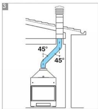

natural_image
Mechanical assembly with pipes and housing components (no visible text or symbols)KIT 1
cod. 261880
flowchart
graph TD
    RE["RE"] --> ST["ST"]
    ST --> TC["TC"]
    TC --> Ja["Ja"]
    Ja --> S["S"]
    S --> VE["VE"]
    VE --> V["AF"]
    V --> SC["Sc 30"]
    SC --> P["P"]
    P --> VST["VST"]
    VST --> VSP["VSP"]
    VSP --> V
    VSP --> VSP
    VSP --> CA["CA"]
    CA --> VI["VR"]
    VI --> MI["MI"]
    MI --> Colector["Colector"]
    Colector --> RA["RA"]
    Colector --> RI["RI"]
    COlector --> T["ACS"]
    COlector --> V
    COlector --> V
    COlector --> V
    COlector --> V
    COlector --> V
    COlector --> V
    COlector --> V
    COlector --> V
    COlector --> V
    COlector --> V
    COlector --> V
    COlector --> V
    COlector --> V
    COlector --> V
    COULTER["EDLKAMIN"] --> TC
    style KIT2 fill:#f9f,stroke:#333,stroke-width:2px
natural_image
Industrial piping system mounted on a metal frame, no visible text or symbolsKIT 2
cod. 261890
flowchart
graph TD
    A["RE"] --> B["ST"]
    B --> C["TC"]
    C --> D["Ja"]
    D --> E["TC"]
    E --> F["S"]
    F --> G["V"]
    G --> H["ACS"]
    H --> I["Colector"]
    I --> J["MI"]
    J --> K["RA"]
    K --> L["RI"]
    L --> M["v"]
    M --> N["ACS"]
    N --> O["VST"]
    O --> P["VSP"]
    P --> Q["SC 30"]
    Q --> R["CA"]
    R --> S["VR"]
    S --> T["NC"]
    T --> U["SA"]
    U --> V["SA"]
    V --> W["SA"]
    W --> X["SA"]
    X --> Y["SA"]
    Y --> Z["SA"]
    Z --> AA["SA"]
    AA --> AB["SA"]
    AB --> AC["SA"]
    AC --> AD["SA"]
    AD --> AE["SA"]
    AE --> AF["SA"]
    AF --> AG["SA"]
    AG --> AH["SA"]
    AH --> AI["SA"]
    AI --> AJ["SA"]
    AJ --> AK["SA"]
    AK --> AL["SA"]
    AL --> AM["SA"]
    AM --> AN["SA"]
    AN --> AO["SA"]
    AO --> AP["SA"]
    AP --> AQ["SA"]
    AQ --> AR["SA"]
    AR --> AS["SA"]
    AS --> AT["SA"]
    AT --> AU["SA"]
    AU --> AV["SA"]
    AV --> AW["SA"]
    AW --> AX["SA"]
    AX --> AY["SA"]
    AY --> AZ["SA"]
    AZ --> BA["SA"]
    BA --> BB["SA"]
    BB --> BC["SA"]
    BC --> BD["SA"]
    BD --> BE["SA"]
    BE --> BF["SA"]
    BF --> BG["SA"]
    BG --> BH["SA"]
    BH --> BI["SA"]
    BI --> BJ["SA"]
    BJ --> BK["SA"]
    BK --> BL["SA"]
    BL --> BM["SA"]
    BM --> BN["SA"]
    BN --> BO["SA"]
    BO --> BP["SA"]
    BP --> BQ["SA"]
    BQ --> BR["SA"]
    BR --> BS["SA"]
    BS --> BT["SA"]
    BT --> BU["SA"]
    BU --> BV["SA"]
    BV --> BW["SA"]
    BW --> BX["SA"]
    BX --> BY["SA"]
    BY --> BZ["SA"]
ACS: Agua caliente Sanitaria
AF: Agua fria
CA: Caldera mural
EV: Electroválvula de 3 vias
F: Fluxostato
natural_image
Industrial piping system with valves and valves mounted on a metal frame (no visible text or labels)KIT 3
cod. 261900
natural_image
Pure electrical circuit lines without any symbolsKIT N3
cod. 627690
INT: interruptor general
TCN: Termostato de contacto
natural_image
Pure electrical circuit lines without any symbolsKIT N3 BIS
cod. 627860
natural_image
Industrial equipment setup with pressure regulator and piping (no visible text or symbols)KIT 5
cod. 280590
natural_image
Industrial equipment unit labeled 'KIT 6' with no visible text or symbols on the main bodynatural_image
Front view of a control panel with buttons and display (no visible text or symbols)natural_image
Three different types of industrial valve fittings (no text or symbols visible)natural_image
Close-up of a metallic valve fitting with coiled cable, no visible text or symbolsnatural_image
White portable electronic device with control panel and cable (no visible text or symbols)natural_image
Mechanical sensor device with black housing and cable, no visible text or symbolsFluxostato (220830)
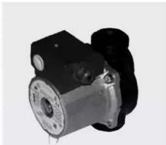
natural_image
Close-up of a mechanical pump or motor component (no visible text or symbols)Circulador UPS 25-50 cod. 219660 UPS 25-60 cod. 238270
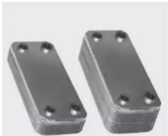
natural_image
Two metallic rectangular electronic components with four mounting holes, shown side by side (no text or symbols visible)natural_image
Black rectangular electronic component with two cylindrical ports and a small label on its side (no readable text or symbols)natural_image
Simple line drawing of a wire with two curved ends and a small black plug attached (no text or symbols)Rustidor Idro 50-70 cod. 234560 Idro 100 cod. 236710
natural_image
Exterior view of a portable electrical enclosure with labeled components (E), showing internal wiring and a close-up of a mechanical component (no readable text or symbols)natural_image
Technical line drawing of a mechanical assembly with no visible text or symbols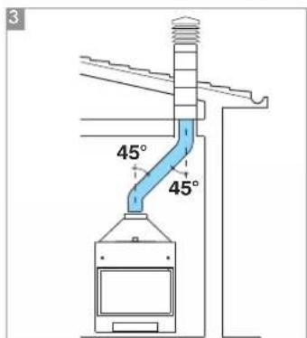
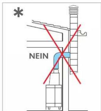
natural_image
Industrial piping system with valves and valves mounted on a metal frame (no visible text or labels)natural_image
Industrial piping system mounted on a metal enclosure, no visible text or symbolsnatural_image
Industrial piping system with valves and valves mounted on a metal frame (no visible text or labels)flowchart
graph TD
    A["Stromnetz 028 cm"] --> B["S"]
    B --> C["TCN"]
    C --> D["ST"]
    D --> E["VE"]
    E --> F["AF"]
    F --> G["VA"]
    G --> H["RE"]
    H --> I["P1"]
    I --> J["V"]
    J --> K["VA"]
    K --> L["CA"]
    L --> M["TA"]
    M --> N["WR"]
    N --> O["Sammelleitung"]
    O --> P["RA"]
    P --> Q["V"]
    Q --> R["ACS"]
    R --> S["ACS"]
    S --> T["VR"]
    T --> U["VR"]
    U --> V["VR"]
    V --> W["WR"]
    W --> X["WR"]
    X --> Y["WR"]
    Y --> Z["WR"]
    Z --> AA["WR"]
    AA --> AB["WR"]
    AB --> AC["WR"]
    AC --> AD["WR"]
    AD --> AE["WR"]
    AE --> AF["WR"]
    AF --> AG["WR"]
    AG --> AH["WR"]
    AH --> AI["WR"]
    AI --> AJ["WR"]
    AJ --> AK["WR"]
    AK --> AL["WR"]
    AL --> AM["WR"]
    AM --> AN["WR"]
    AN --> AO["WR"]
    AO --> AP["WR"]
    AP --> AQ["WR"]
    AQ --> AR["WR"]
    AR --> AS["WR"]
    AS --> AT["WR"]
    AT --> AU["WR"]
    AU --> AV["WR"]
    AV --> AW["WR"]
    AW --> AX["WR"]
    AX --> AY["WR"]
    AY --> AZ["WR"]
CA: Wandheizkessel
PR: Umwälzpumpe
natural_image
Pure electrical circuit lines without any symbolsnatural_image
Pure electrical circuit lines without any symbolsnatural_image
Industrial pressure pump unit with control panel and piping (no visible text or symbols)natural_image
Industrial equipment setup with pressure vessel, tubing, and control panel (no visible text or symbols)natural_image
Front view of a control panel with buttons and display (no visible text or symbols)natural_image
Three different types of industrial valve fittings (no text or symbols visible)natural_image
Close-up of a metallic T-shaped valve with coiled cable, no visible text or symbolsnatural_image
White electronic device with analog buttons and a coiled cable (no visible text or symbols)natural_image
Mechanical pressure sensor device with black housing and coiled cable (no visible text or symbols)natural_image
Mechanical component with black and metallic parts, no visible text or symbolsnatural_image
Two metallic rectangular electronic components with four mounting holes (no text or symbols visible)natural_image
Black rectangular electronic device with three cylindrical ports and a small label on the side (no readable text or symbols)natural_image
Simple line drawing of a pair of electrical components (no text or symbols)Bratspieß Idro 50-70 cod. 234560 Idro 100 cod. 236710
natural_image
Exterior view of a portable industrial machine with internal components and labeled ports (E), no readable text or symbols beyond labelsRookgaskanalen en schoorsteen
natural_image
Technical line drawing of a mechanical assembly with no visible text or symbols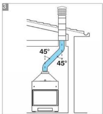
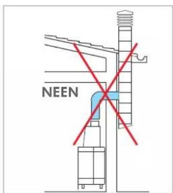
INSTRUCTIES VOOR INSTALLATIE EN GEBRUIK
natural_image
Industrial piping system mounted on a metal frame, no visible text or symbolsPAKKET 1
cod. 261880
VOOR EEN CORRECTE WERKING MOET U DE BUIZEN VOOR TOEVOER EN RETOUR KRUISEN.
VOORBEELD VAN EEN HYDRAULISCHE INSTALLATIE VOOR INBOUWHAARD ZONDER PRODUCTIE VAN WARM TAPWATER+WANDKETEL
MET GEBRUIK VAN
PAKKET 2
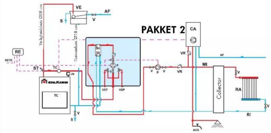
flowchart
graph TD
    A["RE"] --> B["ST"]
    B --> C["TC"]
    C --> D["Ja"]
    D --> E["SC 30"]
    E --> F["P"]
    F --> G["VST"]
    G --> H["VSP"]
    H --> I["VA"]
    I --> J["CA"]
    J --> K["MI"]
    K --> L["Collector"]
    L --> M["RA"]
    M --> N["RI"]
    N --> O["T"]
    O --> P["ACS"]
    P --> Q["VA"]
    Q --> R["VA"]
    R --> S["VA"]
    S --> T["VA"]
    T --> U["VA"]
    U --> V["VA"]
    V --> W["VA"]
    W --> X["VA"]
    X --> Y["VA"]
    Y --> Z["VA"]
    Z --> AA["VA"]
    AA --> AB["VA"]
    AB --> AC["VA"]
    AC --> AD["VA"]
    AD --> AE["VA"]
    AE --> AF["VA"]
    AF --> AG["VA"]
    AG --> AH["VA"]
    AH --> AI["VA"]
    AI --> AJ["VA"]
    AJ --> AK["VA"]
    AK --> AL["VA"]
    AL --> AM["VA"]
    AM --> AN["VA"]
    AN --> AO["VA"]
    AO --> AP["VA"]
    AP --> AQ["VA"]
    AQ --> AR["VA"]
    AR --> AS["VA"]
    AS --> AT["VA"]
    AT --> AU["VA"]
    AU --> AV["VA"]
    AV --> AW["VA"]
    AW --> AX["VA"]
AF: Koud water
CA: Wandketel
P: Pomp (circulator)
RA: Radiators
natural_image
Industrial piping system mounted on a metal frame, no visible text or symbolsPAKKET 2 cod. 261890
VOORBEELD VAN EEN HYDRAULISCHE INSTALLATIE VOOR INBOUWHAARD MET PRODUCTIE VAN WARM TAPWATER+WANDKETEL
MET GEBRUIK VAN
PAKKET 3
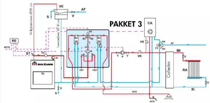
flowchart
graph TD
    A["RE"] --> B["ST"]
    B --> C["TC"]
    C --> D["SC 30"]
    D --> E["VST"]
    E --> F["VSP"]
    F --> G["PAKKET 3"]
    G --> H["Collector"]
    H --> I["MI"]
    I --> J["RA"]
    J --> K["RI"]
    K --> L["ACS"]
    L --> M["ACS"]
    M --> N["S"]
    N --> O["VE"]
    O --> P["S"]
    P --> Q["AF"]
    Q --> R["TC"]
    R --> S["Tcvoertouin Ø28 cm"]
    S --> T["VE"]
    T --> U["S"]
    U --> V["VE"]
    V --> W["AF"]
    W --> X["CA"]
    X --> Y["VR"]
    Y --> Z["NI"]
    Z --> AA["RA"]
    AA --> AB["RI"]
    AB --> AC["ACS"]
ACS: Warm tapwater
AF: Koud water
CA: Wandketel
P: Pomp (circulator)
RA: Radiators
natural_image
Industrial piping system with valves and valves (no visible text or labels)PAKKET 3 cod. 261900
VOOR EEN CORRECTE WERKING MOET U DE BUIZEN VOOR TOEVOER EN RETOUR KRUISEN
VOORBEELD VAN EEN HYDRAULISCHE INSTALLATIE VOOR INBOUWHAARD MET PRODUCTIE VAN WARM TAPWATER+WANDKETEL MET GEBRUIK VAN PAKKET N3
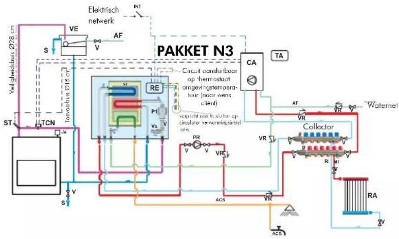
flowchart
graph TD
    A["Verlighedstuis Ø28 cm"] --> B["TCN"]
    B --> C["St"]
    C --> D["VA"]
    D --> E["S"]
    E --> F["VE"]
    F --> G["AF"]
    G --> H["V"]
    H --> I["RE"]
    I --> J["P1"]
    J --> K["Vs V"]
    K --> L["CA"]
    L --> M["TA"]
    M --> N["VR"]
    N --> O["Woternet"]
    O --> P["Collector"]
    P --> Q["RA"]
    Q --> R["V"]
    R --> S["ACS"]
    S --> T["ACS"]
    T --> U["VR"]
    U --> V["VR"]
    V --> W["VR"]
    W --> X["VR"]
    X --> Y["VR"]
    Y --> Z["VR"]
    Z --> AA["VR"]
    AA --> AB["VR"]
    AB --> AC["VR"]
    AC --> AD["VR"]
    AD --> AE["VR"]
    AE --> AF["VR"]
    AF --> AG["VR"]
    AG --> AH["VR"]
    AH --> AI["VR"]
    AI --> AJ["VR"]
    AJ --> AK["VR"]
    AK --> AL["VR"]
    AL --> AM["VR"]
    AM --> AN["VR"]
    AN --> AO["VR"]
    AO --> AP["VR"]
    AP --> AQ["VR"]
    AQ --> AR["VR"]
    AR --> AS["VR"]
    AS --> AT["VR"]
    AT --> AU["VR"]
    AU --> AV["VR"]
natural_image
Pure electrical circuit lines without any symbolsPAKKET N3 cod. 627690
VOORBEELD VAN EEN HYDRAULISCHE INSTALLATIE VOOR INBOUWHAARD MET PRODUCTIE VAN WARM TAPWATER+WANDKETEL
MET GEBRUIK VAN PAKKET N3 BIS
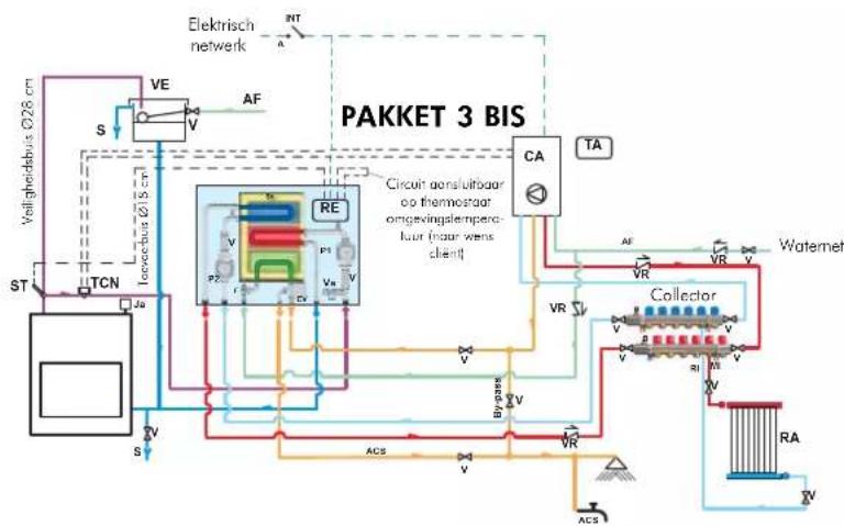
flowchart
graph TD
    A["St"] --> B["TCN"]
    B --> C["Toorbus Ø15 cm"]
    C --> D["VE"]
    D --> E["S"]
    E --> F["Re"]
    F --> G["P2"]
    F --> H["P1"]
    F --> I["Va"]
    F --> J["V"]
    F --> K["Va"]
    F --> L["Va"]
    F --> M["Va"]
    F --> N["Va"]
    F --> O["Va"]
    F --> P["Va"]
    F --> Q["Va"]
    F --> R["Va"]
    F --> S["Va"]
    F --> T["Va"]
    F --> U["Va"]
    F --> V["Va"]
    F --> W["Va"]
    F --> X["Va"]
    F --> Y["Va"]
    F --> Z["Va"]
    F --> AA["Va"]
    F --> AB["Va"]
    F --> AC["Va"]
    F --> AD["Va"]
    F --> AE["Va"]
    F --> AF["Va"]
    F --> AG["Va"]
    F --> AH["Va"]
    F --> AI["Va"]
    F --> AJ["Va"]
    F --> AK["Va"]
    F --> AL["Va"]
    F --> AM["Va"]
    F --> AN["Va"]
    F --> AO["Va"]
    F --> AP["Va"]
    F --> AQ["Va"]
    F --> AR["Va"]
    F --> AS["Va"]
    F --> AT["Va"]
    F --> AU["Va"]
    F --> AV["Va"]
    F --> AW["Va"]
    F --> AX["Va"]
    F --> AY["Va"]
    F --> AZ["Va"]
    F --> BA["Va"]
    F --> BB["Va"]
    F --> BC["Va"]
    F --> BD["Va"]
    F --> BE["Va"]
    F --> BF["Va"]
    F --> BG["Va"]
    F --> BH["Va"]
    F --> BI["Va"]
    F --> BJ["Va"]
    F --> BK["Va"]
    F --> BL["Va"]
    F --> BM["Va"]
    F --> BN["Va"]
    F --> BO["Va"]
    F --> BP["Va"]
    F --> BQ["Va"]
    F --> BR["Va"]
    F --> BS["Va"]
    F --> BT["Va"]
    F --> BU["Va"]
    F --> BV["Va"]
    F --> BW["Va"]
    F --> BX["Va"]
    F --> BY["Va"]
    F --> BZ["Va"]
CA Muurketel
P2 Pomp (circulator)
P1: Pomp primair circuit
natural_image
Pure electrical circuit lines without any symbolsPAKKET N3 BIS cod. 627860
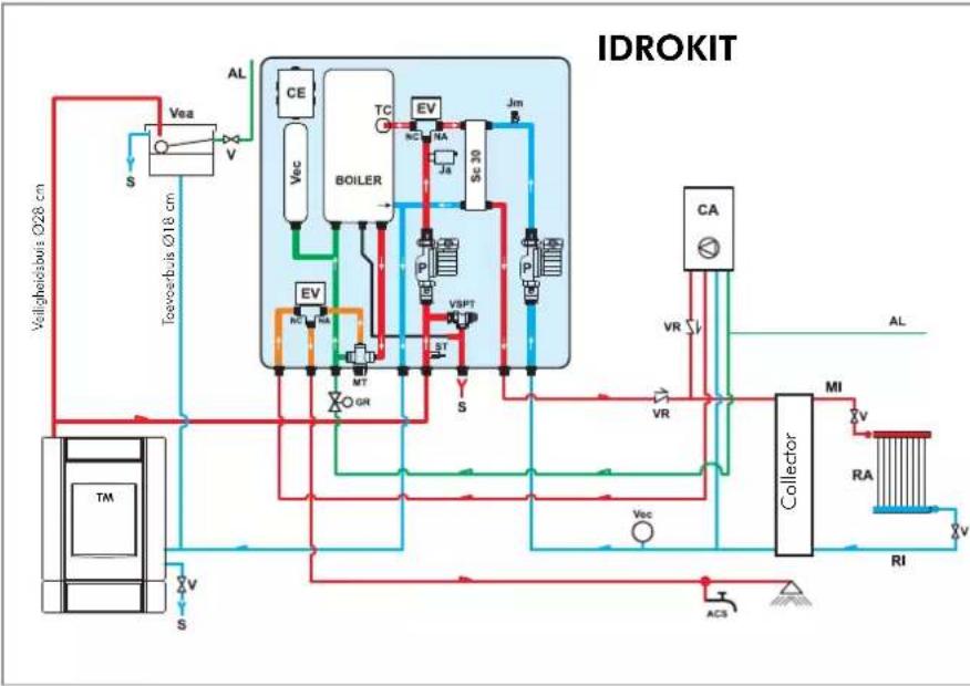
flowchart
graph TD
    A["Valighoebuis Ø28 cm"] --> B["Vea"]
    B --> C["S"]
    C --> D["Toevoorbis Ø18 cm"]
    D --> E["VEa"]
    E --> F["VEc"]
    F --> G["BEILER"]
    G --> H["TC"]
    H --> I["EV"]
    I --> J["SC 30"]
    J --> K["Jm"]
    K --> L["P"]
    L --> M["P"]
    M --> N["VA"]
    N --> O["VR"]
    O --> P["Collector"]
    P --> Q["MI"]
    Q --> R["RA"]
    R --> S["RI"]
    S --> T["AC3"]
    T --> U["Valighoebuis Ø28 cm"]
    U --> V["S"]
    V --> W["VEa"]
    W --> X["V"]
    X --> Y["VEc"]
    Y --> Z["BEILER"]
    Z --> AA["TC"]
    AA --> AB["EV"]
    AB --> AC["SC 30"]
    AC --> AD["Jm"]
    AD --> AE["P"]
    AE --> AF["P"]
    AF --> AG["VA"]
    AG --> AH["VA"]
    AH --> AI["VA"]
    AI --> AJ["VA"]
    AJ --> AK["VA"]
    AK --> AL["VA"]
    AL --> AM["VA"]
    AM --> AN["VA"]
    AN --> AO["VA"]
    AO --> AP["VA"]
    AP --> AQ["VA"]
    AQ --> AR["VA"]
    AR --> AS["VA"]
    AS --> AT["VA"]
    AT --> AU["VA"]
    AU --> AV["VA"]
ACS: Warm tapwater
AF: Koud water
P: Pomp (circulator)
RA: Radiators
RI: Retour installatie
S: Afvoer
2 warm tapwater gasketel
P: Pomp (circulator)
RA: Radiators
natural_image
Industrial piping and valve assembly (no visible text or symbols)PAKKET 5 cod. 280590
INSTALLATIE VOOR MONTAGE MET GESLOTEN VAT
P: Pomp (circulator)
RA: Radiators
natural_image
Industrial equipment setup with pressure vessel, tubing, and control panel (no visible text or symbols)PAKKET 6 cod. 280600
R reg. opening driewegklep (KIT 1 - 3 - 5 - 6)
R reg. werking circulators (PAKKET 2)
RIC interne afstelling pomp
S keuzeschakelaar MAN-OFF-AUTO
SP controlelamp pomp
natural_image
Front view of a white electronic device with control panel and indicator lights (no visible text or symbols)natural_image
Three different types of industrial valve fittings (no text or symbols visible)natural_image
Close-up of a metallic T-joint valve with coiled cable (no text or symbols visible)natural_image
White portable electronic device with control panel and cable (no visible text or symbols)natural_image
Close-up of a mechanical pressure sensor with a black housing and cable (no visible text or symbols)Debietregelaar (220830)
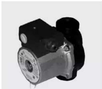
natural_image
Close-up of a mechanical pump or motor component (no visible text or symbols)Circulator UPS 25-50 code 219660 UPS 25-60 code 238270
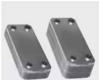
natural_image
Two metallic rectangular electronic components with four mounting holes (no text or symbols visible)natural_image
Black rectangular electronic component with three cylindrical ports and a small label (no readable text or symbols)3-wegs warmteuitwisselaar code 627780
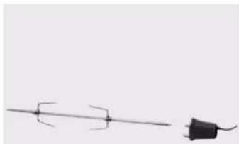
natural_image
Simple line drawing of a pair of wires with a separate plug (no text or symbols)Spit Idro 50-70 cod. 234560 Idro 100 cod. 236710

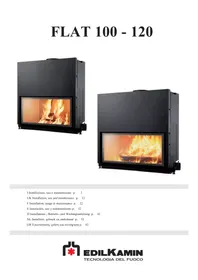
- IMPIANTO PER INSTALLAZIONE A VASO APERTO
- REGOLATORE ELETTRONICO (KIT 1-2-3-5-6)
- IMPORTANT WARNINGS:
- The thermo fireplace must never function without water in the system.
- It can be damaged if it is ignited with no water in the system.
- WARNING:
- TECHNICAL DATA
- GENERAL SAFETY REGULATIONS
- Year
- OPEN TANK
- NB:
- WATER TREATMENT
- CLOSED TANK additional regulations to those specified above (VALID ONLY FOR IDRO 50/CS)
- Chimney flues and chimneypot
- (fig. A 1-2-3).
- The fundamental characteristics of the chimney pot are:
- Transporting the fireplace
- Fireplace
- Practical advice
- Igniting the fireplace
- During the combustion process
- Adjusting the air
- Maintenance
- Cleaning the hearth
- Cleaning and replacing the glass
- \* optional components
- SELECTOR FUNCTIONS
- SYSTEM FOR A CLOSED TANKINSTALLATION
- electronic regulator
- IMPORTANT ADVICE REGARDING THE INSTALLATION
- Compliance with regulations regarding the earth connection is fundamental for the safety of people.
- LEGEND
- Operation
- - Control device:
- - Protection device
- (acoustic alarm system):
- - Power supply device
- (circulation system):
- - Operation device (setting system):
- Attention:
- Positioning
- Installation
- The power supply must be disconnected from the mains and the AUTO-OFF-MAN selector (S) must be in the OFF position when all these operations are carried out.
- ELECTRONIC REGULATOR (Optional)
- HEAT EXCHANGER FOR SANITARY WATER (Optional)
- INSTRUCTIONS POUR L'INSTALLATION ET L'UTILISATION
- SYSTÈME POUR INSTALLATION À VASE FERMÉ
- INSTRUCTIES VOOR INSTALLATIE EN GEBRUIK
- VOORBEELD VAN EEN HYDRAULISCHE INSTALLATIE VOOR INBOUWHAARD MET PRODUCTIE VAN WARM TAPWATER+WANDKETEL MET GEBRUIK VAN PAKKET N3
- INSTALLATIE VOOR MONTAGE MET GESLOTEN VAT
Brand : EDILKAMIN
Model : IDRO 50
Category : Fireplace