DOUBLE - Fireplace EDILKAMIN - Free user manual and instructions
Find the device manual for free DOUBLE EDILKAMIN in PDF.


| Product type | Wood fireplace |
| Brand | Edilkamin |
| Model | DOUBLE |
| Useful power | 13 kW |
| Wood consumption | 3,8 kg/h |
| Efficiency | 75 % |
| Smoke outlet diameter | 30 cm |
| External air intake diameter | 12,5 cm |
| Weight (packed) | 367 kg |
| Indicative heated volume | 340 m³ |
| Firebox material | Ecokeram® (refractory mullite fired at 1200 °C) |
| Structure material | Hermetically welded high-quality steel plate |
| Glass | Ceramic glass resistant to thermal shock up to 800 °C |
| Draft type | Natural convection (version N) or forced (version V with optional kit) |
| Combustion air adjustment | Primary air adjustable by movable deflector, secondary air pre-calibrated for glass cleaning |
| Door | Sliding with adjustable counterweights (adding washers) |
| Handle | Removable, inserts onto the door rods |
| Fuel | Dry natural wood (less than 20% moisture) or wood briquettes |
| Glass cleaning | When cold with a specific product (e.g. GlassKamin) and a cloth |
| Standards | EN 13240:2001 + A2:2004 + AC:2006 + AC:2007, Règlement UE 305/2011 (CPR) |
| Warranty | Subject to proper use and installation according to instructions (see manual) |
Frequently Asked Questions - DOUBLE EDILKAMIN
User questions about DOUBLE EDILKAMIN
0 question about this device. Answer the ones you know or ask your own.
Ask a new question about this device
Download the instructions for your Fireplace in PDF format for free! Find your manual DOUBLE - EDILKAMIN and take your electronic device back in hand. On this page are published all the documents necessary for the use of your device. DOUBLE by EDILKAMIN.
USER MANUAL DOUBLE EDILKAMIN
natural_image
Exterior view of a black industrial stove with visible flames and wood inside (no text or symbols)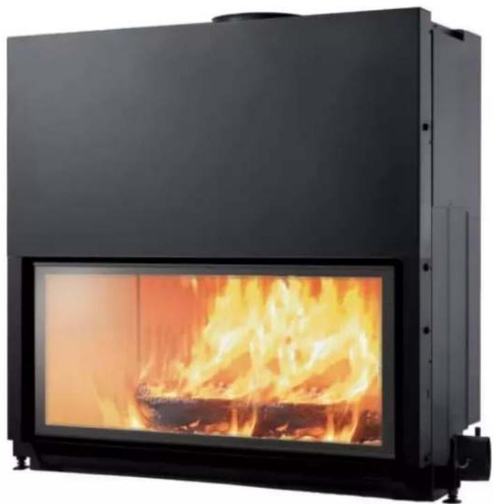
natural_image
Exterior view of a black industrial stove burner with visible flames and firewood (no text or symbols)UK Installation, use and maintenance p. 12
F Installation, usage et maintenance p. 22
fig.1
natural_image
Interior view of a room with a wall-mounted shower structure and a numbered label (6) on the left side (no text or symbols on the structure itself)fig.2
natural_image
Close-up of a metal shelf with two circular cutouts and a numbered label '14' on the wall (no readable text or symbols beyond the number)fig.3

natural_image
Close-up of a black industrial machine component with labeled parts (10 and 11), no visible text or symbols beyond labels.fig.4
natural_image
Metal bracket component with two notches and a labeled point (8) on the side (no text or symbols beyond label)fig.5
natural_image
Mechanical device labeled 'A' with no visible text or symbols on the body itselfnatural_image
Mechanical component with black shaft and bolted joint, labeled 'fig.7' (no text or symbols on the object itself)Valvola a farfalla
natural_image
Mechanical component with threaded shaft and bolts (no visible text or symbols)natural_image
Technical line drawing of a mechanical assembly with two labeled components A (no text or symbols beyond labels)natural_image
Technical line drawing of a mechanical device with mounting holes and structural supports (no text or symbols)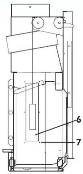
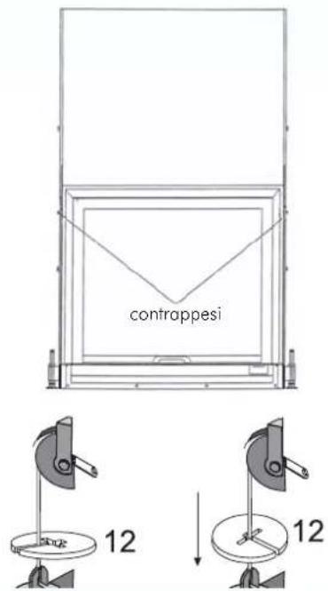
fig.11
natural_image
Isometric diagram of a ceiling HVAC unit with airflow arrows and ventilation ducts (no text or labels)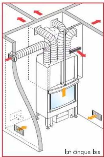
natural_image
Close-up of a metallic door with a white arrow pointing to a small mark, no visible text or symbols.natural_image
Simple black line drawing of a mechanical lever handle (no text or symbols)mano fredda
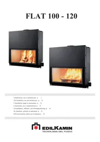
Thank you for having chosen FLAT.
You are kindly asked to read through this information before using the fireplace in order for you to make use of all its features in total safety.
In the event of any doubt, a request for spare parts or complaints, you should contact the Dealerwhom you bought it from, quoting the details on the manufacturer's sticker and the type of appliance.
The number on the manufacturer's sticker is necessary for identification of the fireplace and this is found in the documentation enclosed with it and also on the plate fixed on its front.
The documentation in question must be kept for identification.
- You must keep these instructions as you will need them for any information requests.
- The details are shown indicatively, both graphically and geometrically.
Safety information
The FLAT fireplace is designed to warm up the room/premises where it is placed by means of radiation and movement of warm air. The only hazards that can derive from using the fireplace pertain to non-compliance with the installation instructions or if contact is made with the fire or hot parts (glass, pipes, hot air outlet) or if foreign substances are put in the fireplace.
The only combustible material to be used is firewood.
No flammable products are to be used to clean the smoke flue.
The glass is to be cleaned when COLD and with suitable products (e.g. GlassKamin) and a cloth.
Do not clean when hot.
The exhaust pipes and the door reach hot temperatures when the fireplace is used.
Do not place anything which is not heat resistant near the fireplace.
NEVER use combustible liquids to light the fireplace or to rekindle the embers.
Do not obstruct the air ventilation openings in the room where the fireplace is installed, nor the air inlets of the fireplace.
Do not wet the fireplace.
Do not use reducers on the smoke exhaust pipes.
The fireplace must be installed in a place which is suitable against fire hazards and equipped with all that is required for the fireplace to function properly and safely.
Important note
If the FLAT hearth malfunctions you are to contact the Dealer whom you bought it from or the Edilkamin dealer in your area.
Use only the manufacturer's original spare parts as this is the only way to be certain that the fireplace operates safely. Improper use of the appliance will result in forfeiture of the warranty.
Proper use of the appliance means adhering to these operation instructions, the UNI 10683 standard, correct installation and operation standards.
If installation is carried out in Italy, refer to the standard issued by the Italian Organisation for Standardisation: UNI 10683 or subsequent amendments. In all other countries, please verify the laws and regulations in this regard.
The undersigned EDILKAMIN S.p.a. with head office headquarters at Via Vincenzo Monti 47 - 20123 Milan - Italy - tax code and VAT no. 00192220192
Declares under its own responsibility as follows:
The wood-combustion fireplace listed below complies with Regulation EU 305/2011 (CPR) and the harmonised European Standard EN 13240:2001 + A2:2004 + AC:2006 + AC:2007
WOOD BURNING FIREPLACES, trademark EDILKAMIN, called FLAT 100-120
Year of manufacture: Ref. Data nameplate
Declaration of performance (DoP - EK 27): Ref. data tag plate
EDILKAMIN S.p.a. will decline all responsibility of malfunctioning or damage to the equipment in case of unauthorized substitution, assembly or modifications of any sort on the said equipment on the part of non-EDILKAMIN personnel.
THE FEATURES
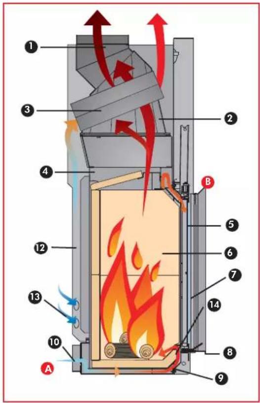
fig.1
natural_image
Interior view of a room with a door, wall-mounted fixture, and numbered label (6) on the left wall.fig.2
natural_image
Close-up of a metal shelf with a numbered label (14) and mounting holes, placed on a wooden panel background (no readable text or symbols)fig.3
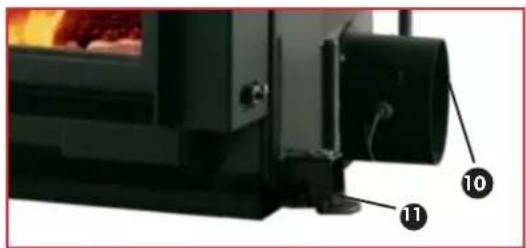
fig.4
natural_image
Metal bracket component with two notches and a labeled point (8) on the side (no text or symbols beyond label)The structure consists of a high-quality, steel plate frame which is hermetically welded, equipped with adjustable feet and complete with an ECOKERAM bowl-shaped hearth, for the ashes to pile-up properly.
The structure's finishing consists of a mantel cover that creates a space for the circulation of warm air.
Heating air circulates via natural convection (N version) or else via an optional forced air kit (V version), see page 15.
Particular attention has been given to the intake of air for combustion in the hearth in order to guarantee optimum combustion, a stable flame and a very clean glass.
The primary combustion air Asters at the base of the hearth on the surface of the embers.
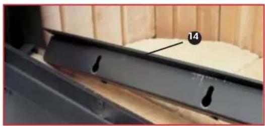
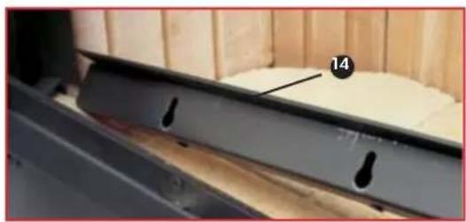
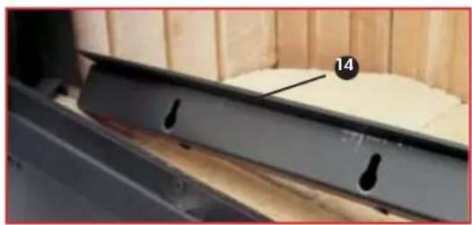
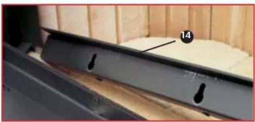
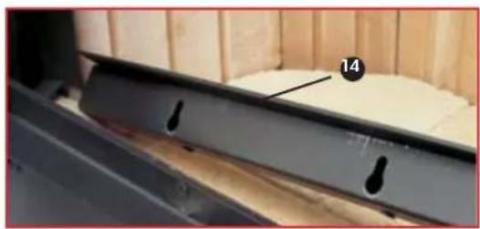
The amount of primary air that enters can be regulated according to the draught that passes through the chimney flue by means of a movable deflector (14) installed on the front part of the fireplace (fig. 3).
If a weak draught passes through the chimney flue you can increase the primary air inlet section by means of the movable deflector. On the other hand you can decrease this if the draught is too strong.
The secondary combustion air B and that which cleans the glass enters from the top of the glass once it is warmed during its path.
The amount of secondary air and that which cleans the glass is pre-set and warmed up as it passes through the side supports placed at the opening of the hearth.
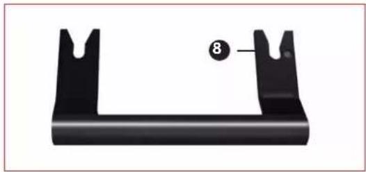
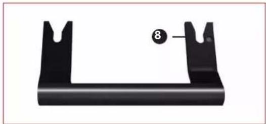
Removable handle for opening the door
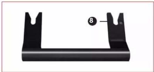
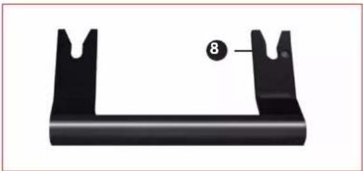
The door handle (fig. 5) is not fixed to the door – it is only attached when necessary.
The handle is fitted into the lower part of the frame around the opening of the hearth, mounting it onto the appropriate pins.
The handle is only used to lift or lower the door.
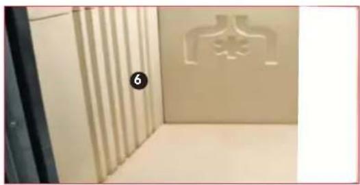
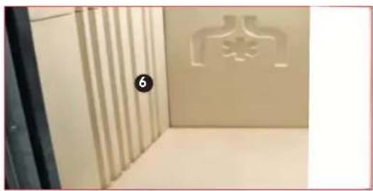
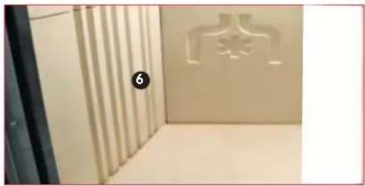
Internal covering of the hearth (fig. 2)
The internal covering is made of ECOKERAM®: a new refractory material containing mullite fired at 1200°C.
ECOKERAM® has a particular characteristic of accumulating heat during combustion and emitting it gradually even when the fireplace is turned off.
ECOKERAM® allows the internal part of the hearth to reach a very high temperature and in doing so optimises combustion and reduces emissions.
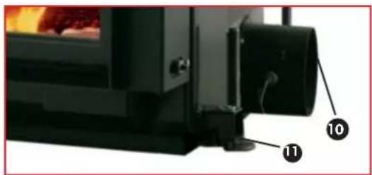
LEGEND: (figs. 1-2-3-4-5)
-
smoke outlet fitting to be connected to the chimney flue
-
finning to improve heat transfer
-
smoke deviating channel to improve heat transfer
-
steel structure
-
channel for the intake of secondary air and that which cleans the glass to keep the glass clean
-
the internal covering of the hearth made of ECOKERAM® which has a thick covering in order to increase the combustion temperature
-
ceramic glass thermal shock resistant at a temperature of 800°C
-
removable handle
-
bowl-shaped hearth to pile-up the embers and obtain optimal combustion
-
external air inlet fitting
-
adjustable feet
-
mantel cover for the circulation of warm air
-
inlets to intake air that is to be heated (recycle)
-
movable deflector
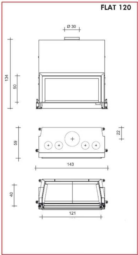
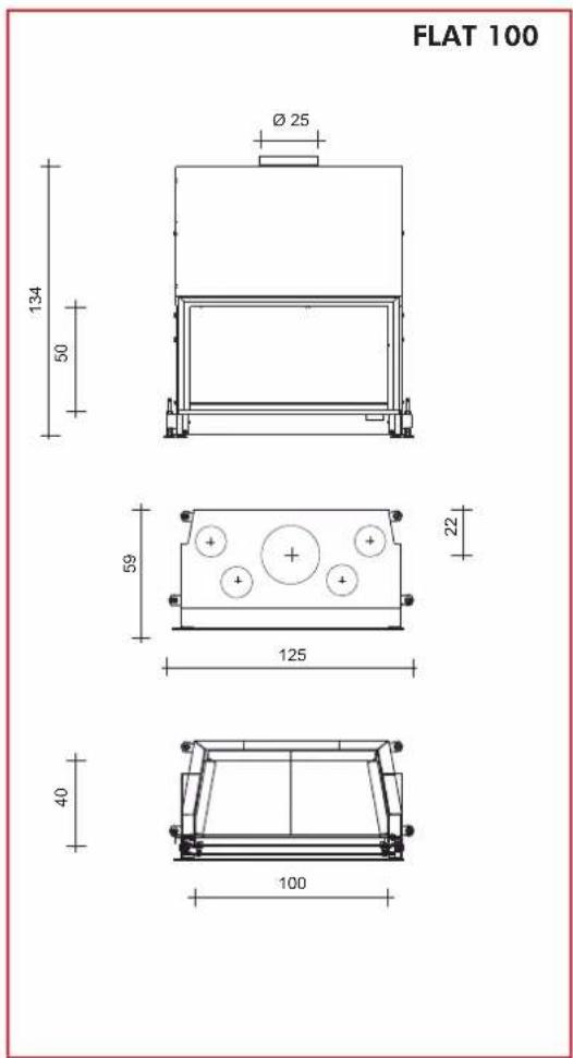
DIMENSIONI
ENGLISH
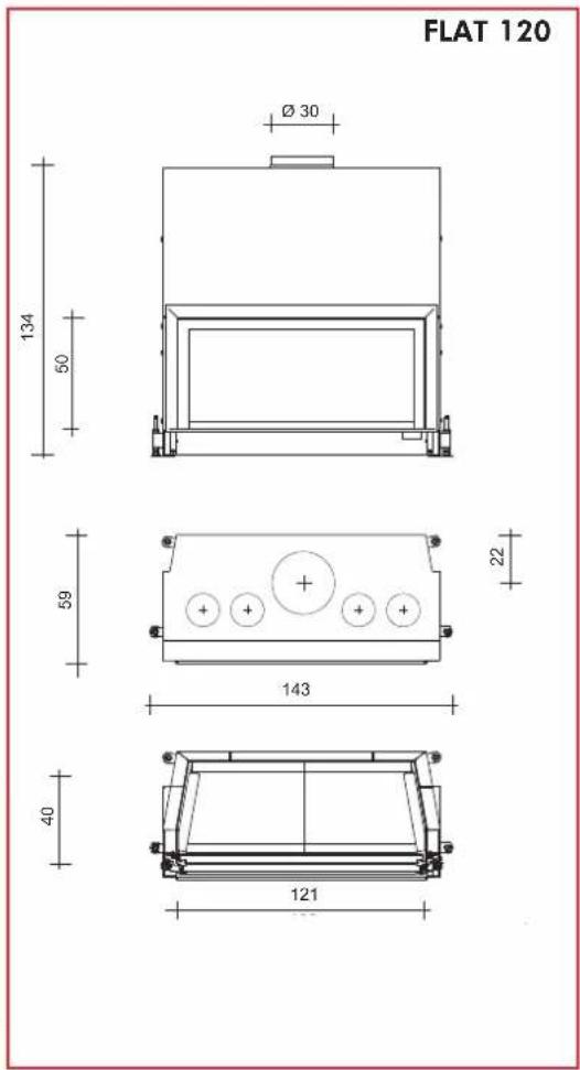
| Technical data | |||
| FLAT 100 FLAT 120 | |||
| power output kW 10,5 13 | |||
| firewood consumption kg/h 3 3,8 | |||
| efficiency % 75 75 | |||
| smoke outlet ∅ cm 25 30 | |||
| air inlet ∅ cm 12,5 * 12,5 * | |||
| weight including packaging | kg | 350 | 367 |
| heating capacity | m^3 | 275 | 340 |
NB: the heating capacity is only indicative as this depends on the conditions of the premises.
* Should the air volume result scarce, and the type of building in which the chimney is installed particularly air sealed, it will be necessary to install a supplementary air inlet of 120 cm ^2 (ø 12.5).
THE TECHNOLOGY

natural_image
Mechanical device with labeled component A, shown from image A (no text or symbols on the device itself)Air for combustion
The FLAT fireplaces can only be installed in places where there is a sufficient supply of air for combustion. For the fireplace to function properly it is fundamental that the air for combustion reaches the hearth through a tube that goes to the appropriate inlets provided on the sides and behind the fireplace. The fitting (A) with a diameter of 12.5 cm is supplied and this is to be applied to the inlet that is to be used (fig. 6).
The external connection must maintain a cross-section of at least 125 cm^2 throughout its path. The outlets that are not used to connect the flexible tube for the combustion air path must remain closed with a cover.
If the air volume is not sufficient and the type of premises in which the fireplace is installed is not sufficiently ventilated, an additional air inlet of 120 cm^2 ( 12.5 cm ) is required.
natural_image
Mechanical component with black shaft and flange, no visible text or symbolsThrottle valve
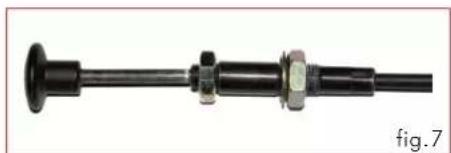
The air for combustion flows to the hearth regulated by a throttle valve.
The throttle valve is supplied as an accessory together with a flexible tube and fastening clips.
The compact fireplace cannot be started-up if the throttle valve is not mounted and set solidly in place.
Mount the lever that regulates the air for combustion in the most suitable position below the edge.
natural_image
Mechanical component with threaded shaft and bolted joint (no visible text or symbols)Adjusting the throttle valve
The "on" position / max. calorific power (fig. 7):
the air valve adjustment lever is pulled out completely. The fireplace is lit up when cold and at maximum power output.
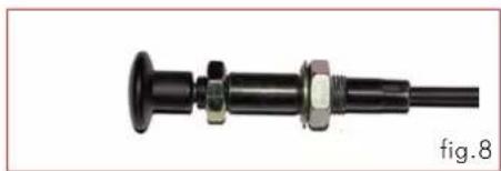
The "maintenance" position (fig. 8):
the valve adjustment lever is entered completely. All air inlets are closed.
The air that is to be heated
- natural convection
Room temperature enters from the side inlets (n 13 - fig.1 on page 13) located on the base of the shell. It warms up and moves along the hollow and comes out hot from the outlets on the cover of the shell itself.
In this mode, the covers of the air inlets on the shell must be removed (n 13 - fig.1 on page 13) and equivalent air passages must be provided for on the coverings in such a way that the air to be heated have easy access to the said inlets.
- forced ventilation
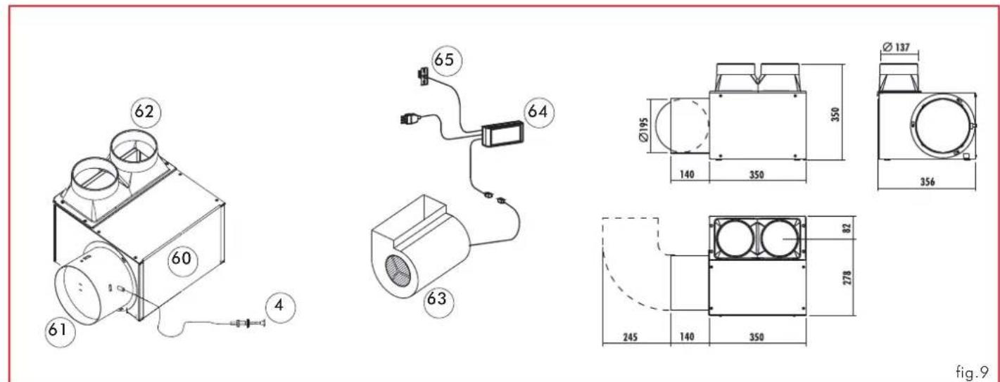
forced hot air circulation is obtained by means of application of a special kit (fig.9)
this kit is composed of a metal box (60), complete with:
- 800 m³/h fan (63)
- regulator (64)
- sensor (65)
- fitting (61) connecting to the external air inlet with smoke damper and wired control (4)
- two-way fitting (62) for conveying external air to the shell
the air box is positioned next to the fireplace, either on the right or left side.
Detailed information for forced ventilation kit installation is contained in its packaging.
INSTALLATION INSTRUCTIONS
Important Notices
Other than that described in this documentation, you are also asked to note the following UNI standards:
- No. 10683 – firewood heat generators: installation requirements.
- No. 9615/90 – calculating the internal dimensions of fireplaces.
Particularly:
- before carrying out any assembly it is important to verify compatibility of the appliance as stipulated in the UNI standard 10683 in paragraphs 4.1 / 4.1.1 / 4.1.2.
- when assembly is completed, the installer must implement "start-up operations" and issue documentation as requested by the UNI standard 10683 in paragraphs 4.6 and 5, respectively.
Before setting up the fireplace covering, verify the proper functionality of all connections, controls and all moving parts.
This verification must be carried out with the fireplace turned on for a couple of hours, before covering the hearth in order to be able to intervene if need be.
After which, the finishing operations such as:
- setting-up the fireplace mantel
- mounting the fireplace covering
- pilasters, painting, etc.
are carried out once verification is completed successfully.
Consequently, Edilkamin does not accept responsibility for expenses deriving from demolition as well as construction even if either occurs as a result after having replaced any damaged parts of the hearth.
The fireplace must only be calibrated and commissioned by a qualified dealer.
Premise
• The FLAT fireplaces must be installed in accordance with the instructions found below, since safety and efficiency depend on correct installation.
• Therefore, read these instructions carefully before proceeding with the assembly procedures.
• EDILKAMIN disclaims any responsibility for any damage deriving from non-compliance with these instructions and should this occur the warranty will be forfeited.
• The FLAT fireplace is supplied assembled and on a disposable pallet.
The internal covering of the hearth comes pre-installed.
• An identification plate is found below the door of the hearth and this indicates the model; the plate remains visible until the hearth is covered.
A model identification number is also shown in the documentation that comes with the product.
Protecting the premises
All areas that are adjacent to the hearth must be protected against overheating.
The insulation that is to be implemented depends on the type of surfaces there are and what material they are made of.
Warm air outlets / Grilles
The warm air outlets must be placed at a minimum distance of 50 cm from the ceiling and 30 cm from furniture.
Place the grilles or the air outlets at the highest point of the covering, in order to avoid an accumulation of heat inside the covering itself. Place the grilles or the air outlets in such a way so as to be easily accessible when cleaning.
Thermal insulation
The insulating layers must not have any bends and must not overlap. The thickness of the insulating material must be at least 3 cm.
Decorative beams
You can have decorative wooden beams in front of the fireplace covering as long as these are out of the radiation range, at a distance of at least 1 cm from the fireplace covering. The space that separates the ornamental components and the fireplace covering must not allow an accumulation of heat. The decorative wooden beams cannot be an integral part of the structure.
The floor in front of the hearth
Flooring made of combustible material must be protected with a sufficiently think non-combustible covering. The floor protection must be as follows:
front-view: equivalent to 30 cm higher than the hearth is to the floor and in any case at least 50 cm from the floor.
sideways: equivalent to 20 cm higher than the hearth is to the floor and in any case at least 30 cm from the floor.
Within the hearth's radiation range
Any structural components that are made of combustible material or may have combustible parts together with furniture must be
placed at a minimum distance of 80 cm from the opening of the hearth, from all three sides: front, upper and lateral.
If such components or furniture are protected by means of anti-radiation ventilation, they can be placed at a distance of 40 cm.
Out of the radiation range
Any structural components that are made of combustible material or may have combustible parts together with furniture must be placed at a minimum distance of 5 cm from the hearth's covering.
The air must circulate freely in this space and there must not be an accumulation of heat.
Power lines
There must be no power lines passing through the walls or ceilings found in the enclosed area of the hearth.
Handling rings.
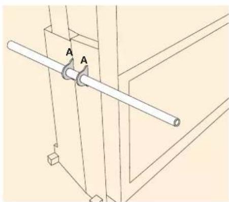
2 rings (A) have been fixed to the sides of the hearth so as to facilitate transportation of the monobloc. Insert the two steel rods, which are supplied, into the rings.
The two rods will be used as support when handling the fireplace manually, after having removed the entire Ecokeram hearth in order to make it become lighter (about 70 kg).
natural_image
Technical line drawing of a mechanical assembly with two labeled components (A), no text or symbols present.Note: The product is supplied with two anti-corrosion discs (one on the outside and one on the inside of the combustion chamber). They must be removed during unpacking and disposed of as normal waste.
INSTALLATION INSTRUCTIONS
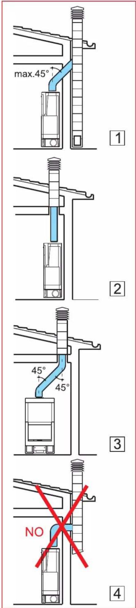
Smoke channel
This refers to the flue that connects the smoke outlet opening of the hearth with the chimney flue inlet.
The smoke channel must be made with rigid tubes made of steel or ceramic material; flexible metal tubes or fibre-cement pipes are not to be used.
Horizontal sections or counterslopes must be avoided.
Any changes to the sections are only allowed upon the chimney outlet and not (for example) upon the insert within the chimney flue.
Angles exceeding 45^ are not allowed.
The junction of the steel flue inlet and the smoke outlet of the fireplace must be sealed with high temperature mastic.
In addition to that mentioned above, you are asked to note the following, with reference to the UNI standard 10683, paragraph 4.2: "connection to the smoke outlet system" and its subsections.
Chimney flue and chimneypot
Chimney flue refers to the flue that reaches the top of the structure from the room where the fireplace is installed.
The fundamental characteristics of the chimney flue are:
- its capacity to withstand a smoke temperature of at least 450 °C with respect to mechanical resistance, insulation and gas capacity
- it must be appropriately insulated so as to prevent condensation forming
- it must have a constant cross-section that is practically vertical and must not have angles exceeding 45°
- preferably, its internal cross-sections are circular; if the cross-sections are rectangular, the relationship between the sides must not exceed 1.5
- it must have an internal cross-section with its surface at least the same as that shown in the technical specifications
- it must pertain to one hearth (fireplace or stove).
If the chimney flue is not brand new or too big it is recommended to fit in stainless steel tubes with an appropriate diameter and suitable insulation.
The fundamental characteristics of the chimney pot are:
- an internal cross-section at the base which is the same as that of the chimney flue
- an outlet cross-section which is no smaller than twice that of the chimney flue
- its position must be high enough to catch the wind and avoid downdraft areas in turbulent wind
INSTALLATION INSTRUCTIONS
INSTALLING COUNTERBALANCES

natural_image
Technical line drawing of a mechanical device with mounting holes and structural supports (no text or symbols)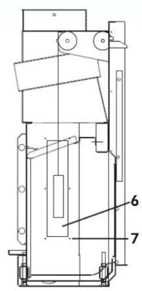
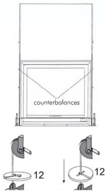
fig.11
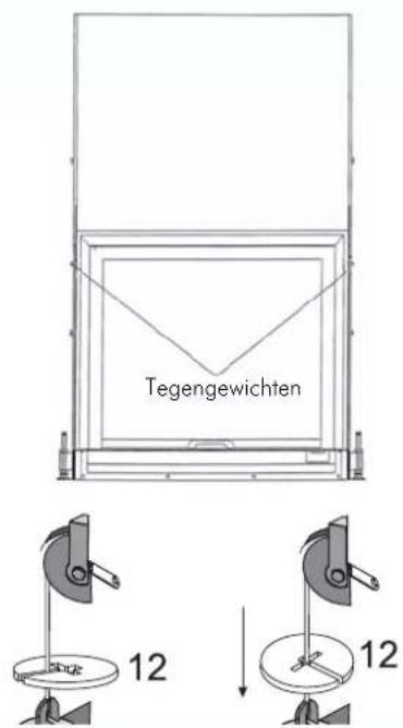
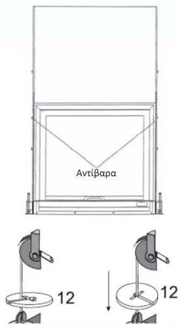
The latch door is equipped with counterbalances which ensure smooth movements as well as closure of the door. The counterbalances can be regulated by adding washer/s (additional counterbalances) that are supplied with the fireplace. The additional counterbalances (washers) can be mounted at any time without removing the fireplace mantel cover.
PROCEDURE (fig. 11):
- Open the latch door completely by pushing it upwards.
- Release the left and right plates which support the walls of the Ecokeram hearth
- Remove the walls of the Ecokeram hearth
- At this point, you will see the lids which close the inspection inlet where the counterbalances are. Remove the lids (6) of these inlets by loosening the six screws (7).
- Place the counterbalance washers (12) which are necessary to balance the door; these washers are supplied.
- Be sure to insert the washers well in the counterbalance housing. The same number of additional counterbalances is to be added on either side.
- Put the sheet metal lids back and put the walls of the hearth back in their position.
- Put back the fastening plates of the hearth's walls.
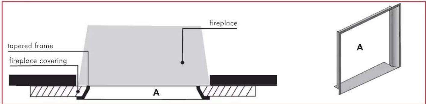
Finishing frame of the fireplace opening
To facilitate matching the FLAT fireplace covering, this can be done with a frame (A), which is to be placed at the front of the fireplace opening.
INSTALLATION INSTRUCTIONS
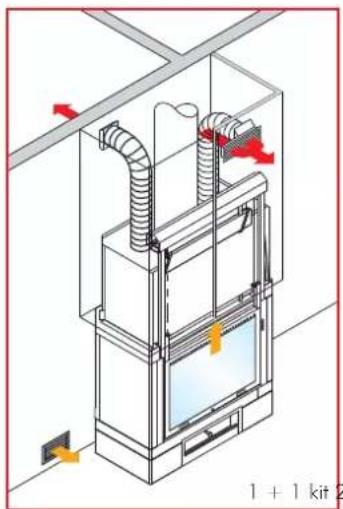
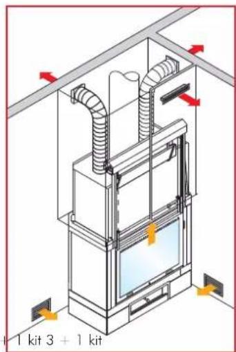
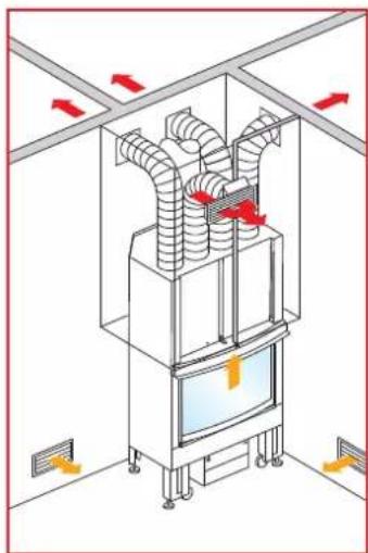
AIR-CHANNELLING KIT
To facilitate implementation of the distribution system of warm air, Edilkamin has prepared specific packages for every hearth used in different situations, from the simplest to the most complex.
Distribution of warm air:
natural_image
Isometric diagram of a ceiling-mounted HVAC unit with airflow arrows and ventilation ducts (no text or labels)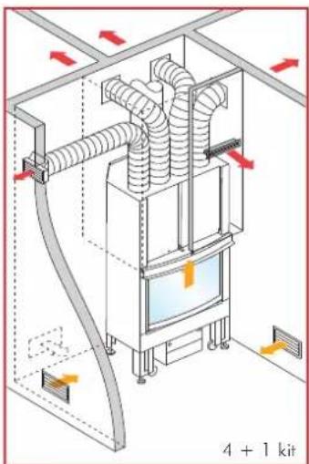
natural_image
Isometric diagram of a building interior with coiled ducts and ventilation ducts, no text or symbols present2 rooms + fireplace room 1 room 3-room place fireplace room
4 rooms + fireplace room
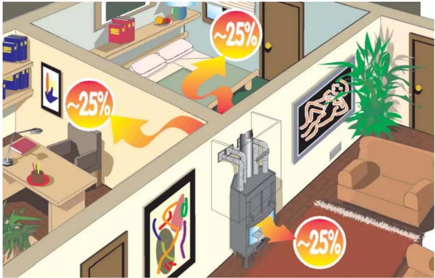
Apart from heat radiation, the FLAT fireplaces produce a large quantity of warm air that can be channelled by means of flexible pipes in order to warm the whole house.
INSTRUCTIONS FOR USE
Combustible material and calorific power
The combustion process has been optimised from a technical point of view, with regards to the design of the hearth and the relative air supply, as well as that pertaining to emissions.
Please support our commitment in keeping the environment clean by observing the information explained below regarding the use of combustible materials which do not contain nor produce harmful substances.
As for combustible material, use only natural, seasoned timber or wood briquettes. Firewood which is damp, freshly cut or stored in unsuitable conditions, has high water content, therefore, it does not burn well, produces smoke and little heat.
Use only firewood that has been seasoned for at least two years in a dry and ventilated environment. That way the water content will be 20% less and therefore, you will save on combustible material since seasoned firewood has calorific power that is reasonably higher.
Never use liquid fuels such as gasoline, alcohol or anything similar. Do not burn waste.
Radiation range
Do not place any combustible material within the radiation range emitted through the glass door.
Initial start-up
The paint with which the hearth is covered is subject to "ageing" until it reaches its operating temperature for the first time.
This can cause unpleasant smells, however, in this case, see that the room where the hearth is installed is adequately ventilated. This occurrence will disappear after the first few times it is lit.
Burn hazards
The external surfaces of the FLAT fireplace become hot, especially the door that is made of ceramic glass. Do not touch these as you risk getting burnt! Warn children about this hazard. Children are to be kept away from the hearth when it is on anyway.
Air grilles
Be careful not to close or block the warm air outlets. This causes the internal part of the covering to overheat, which is a hazard.
Operating the hearth with the door open
When the hearth is used with the door open, you must constantly keep an eye on the hearth. Hot embers can spark out of the hearth.
Adding combustible material
When you wish to "add firewood" it is recommended you use a protective glove as the handle can become hot if the fireplace is used for a long period of time.
Open the door slowly. This way you will avoid causing the air to swirl as this may cause smoke to be emitted.
When should firewood be added? When the combustible material is finishing and all that is left are the embers.
Operating the fireplace in mid-season
To draw in air for combustion and smoke exhaustion, the FLAT fireplace needs a draught from the fireplace/chimney flue. An increase in the temperature outside causes the draught to decrease. When the temperature outside exceeds 10 °C, check the draught in the fireplace before lighting the fire. If the draught is weak, light up the fire in "start-up mode" by using igniting material that is small in size. Once the draught within the fireplace increases and is suitable you can add more combustible material.
Air inflow in the room where the hearth is installed
The FLAT fireplace can only function properly if in the room where it is installed there is a sufficient inflow of air for combustion. Before lighting the fireplace, ensure there is a sufficient inflow of air. If the appliance is equipped with a valve for outside air to enter, open it and leave it open for as long as the fireplace remains on. The devices related to air supply for combustion must not be altered.
If the air volume is not sufficient and the type of premises in which the fireplace is installed is not sufficiently ventilated, the additional air inlet of 150 cm2 mentioned earlier on, is required to be installed.
Lighting a cold hearth
- Ensure the bed of ashes is not too high. The maximum height is 5 cm from the bottom edge of the door.
A bed of ashes that is too high, poses the risk of embers to fall out of the hearth when the door is opened to add firewood.
-
Pull the lever that adjusts the air valve into the "on" position. The air for combustion will flow in intensely towards the firewood in the hearth in order to quickly reach a good level of combustion.
-
The firewood must be placed in the hearth without cramming it too much. Place fire-starters between the wooden logs and light them up. Fire-starters are practical when lighting up combustion material.
Attention: Wooden logs that are big in size do not light up well in a cold hearth and release harmful gases.
Never use combustion material such as gasoline, alcohol or anything similar to light up the hearth!
-
Now close the door of the hearth and monitor it for a few minutes. If the fire should go off, open the door slowly, place another fire-starter in the middle of the wooden logs and light it up.
-
If the fire does not require more firewood to be added, when this fire dies down push the lever that adjusts the air valve into the "maintenance" position. Do not implement this during combustion as when the lever is in the "maintenance" position, the inflow of combustion air is completely blocked. In case of a sudden inflow of oxygen (e.g. caused when opening the door of the hearth), the "gases that are still present" in the hearth and on any surfaces where heat is drawn in, can react violently when atmospheric oxygen enters.
Adding firewood to a hot hearth
Using the glove supplied, slowly lift the door and add the desired amount of firewood in the hearth, placing the wooden logs on the embers. In this way, the firewood warms up and consequently lets off any water content as vapour. This in turn decreases the internal temperature of the hearth. The volatile substances released from the combustible material require sufficient air supply for this stage of emission to take place rapidly (which is critical from a technical point of view) and for the temperature required for a good level of combustion can be reached.
Another suggestion:
When lighting up the fireplace, always use the smaller wooden logs as these burn quicker and therefore, the hearth reaches the right temperature in less time. Use the larger wooden logs when adding firewood to a hot hearth.
Some types of wood briquettes expand once they are placed in the hearth (i.e. the heat causes them to increase in volume).
Always place the firewood at the far end of the hearth, almost touching its back wall so that if it slides down it does not fall against the door.
Removing the ashes
You can remove the ashes with a small sho- vel or a vacuum cleaner for ashes. Place the ashes in NON-COMBUSTIBLE containers. Bear in mind that the residues can even light up after more than 24 hours after combustion.
N.B. Seasoned wood has a calorific power of about 4 kWh/kg, whereas freshly cut firewood has a calorific power of only 2 kWh/kg. Therefore, twice as much is required of the latter to obtain the same calorific power.
| Firewood water content g/Kg | Calorific power kWh/kg | Greater consumption of firewood as a % | |
| Seasoned for a very long time 100 | 4,50 | ||
| Seasoned for two years 200 4 15 | |||
| Seasoned for 1 year 350 3 71 | |||
| Freshly cut firewood 500 2,1 153 |
ATTENTION: If too much combustible material is placed in the hearth or unsuitable combustible material is used, this may provoke an over-heating hazard.
CLEANING AND MAINTENANCE
Cleaning the fireplace
Once every season you must ensure that the smoke flue and all the exhaust channels of combustible gases are clear and free from any residue. Therefore, they have to be cleaned very well.
If need be, remove the volatile ashes with a suitable vacuum cleaner for ashes. Contact the dealer in your area for information pertaining to checking and maintaining procedures.
Cleaning the glass
You can tilt the door of the hearth to clean it.
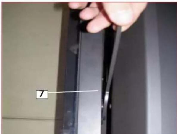
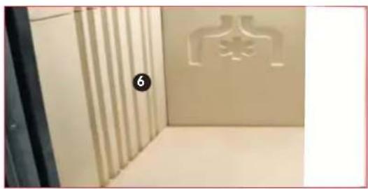
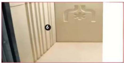
To do this, first block the door in the closed position by turning the locking lever (6 fig. 1) towards the centre.
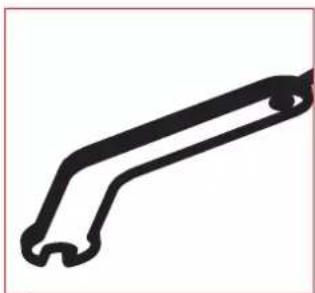
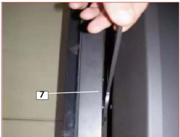
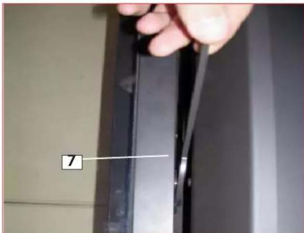
You can now loosen the pawl plates (7-fig. 3) on the left and right side of the door with the appropriate spanner supplied (rotate it by 90^ ).
The door can now be tilted and cleaned.
Once you finish cleaning it, put back the pawl plates (7 - fig. 4) and release the locking lever (6 - fig. 2).
If the glass is slightly dirty, clean it while it is hot with a dry cloth.
If it is very dirty, EDILKAMIN offers an appropriate product called "GlassKamin" and you can find this at authorised dealers.
Never use abrasive products or aggressive detergents!
Never clean when it is hot.
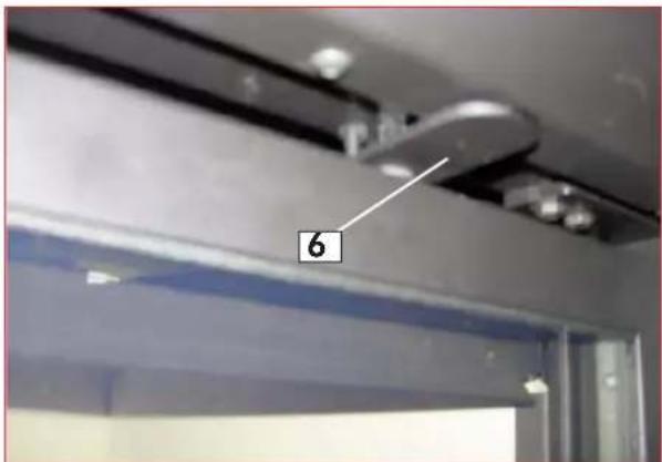
Figure 1 : blocked locking lever
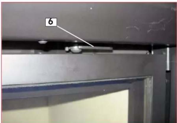
Figure 2 : released locking lever
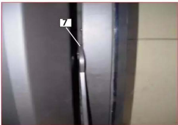
Figure 3 : blocking the door open (rotate the pawl by 90°)
natural_image
Simple line drawing of a mechanical lever or clamp (no text or symbols)Appropriate spanner
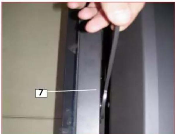
Figure 4 : blocking the door closed (rotate the pawl by 90°)
Madame/ Monsieur
fig.1
natural_image
Interior view of a room with a wall-mounted shower structure and a numbered label (6), no visible text or symbols.fig.2
natural_image
Close-up of a metal shelf with a labeled component (14) and mounting holes, against a textured wall background (no readable text or symbols)fig.3
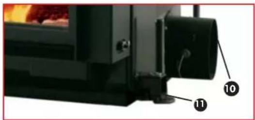
fig.4
natural_image
Metal bracket component with two notches and a numbered label (8) pointing to the side (no text or symbols on the part itself)fig.5
natural_image
Mechanical device with labeled component A and figure number A6 (no text or symbols on the device itself)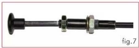
natural_image
Mechanical component with flanged shaft and bolted joint (no visible text or symbols)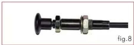
natural_image
Mechanical component with threaded shaft and bolted joint (no visible text or symbols)INSTRUCTIONS POUR L'INSTALLATION
natural_image
Technical line drawing of a mechanical assembly with a rod and two labeled points A (no text or symbols present)natural_image
Technical line drawing of a mechanical device with mounting holes and structural supports (no text or symbols)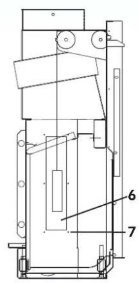
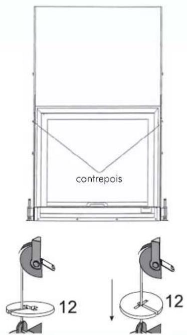
fig.11
KIT CANALISATION AIR
natural_image
Diagram of airflow or ventilation system inside a room with pipes and control panel (no text or symbols)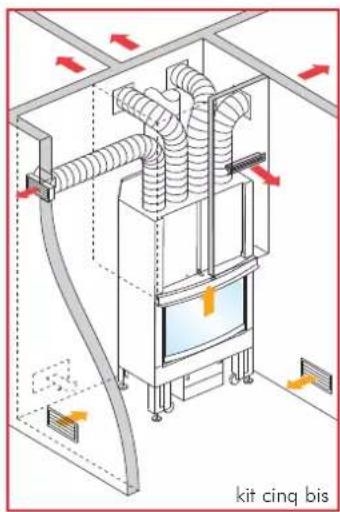
natural_image
Simple line drawing of a mechanical lever or clamp (no text or symbols)Main froide
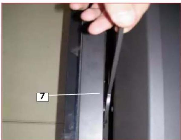
fig.1
natural_image
Interior view of a room with vertical slats and a wall-mounted shower symbol (no text or labels visible)fig.2
natural_image
Close-up of a metal shelf with a numbered label '14' pointing to a textured surface (no readable text or symbols beyond the number)fig.3
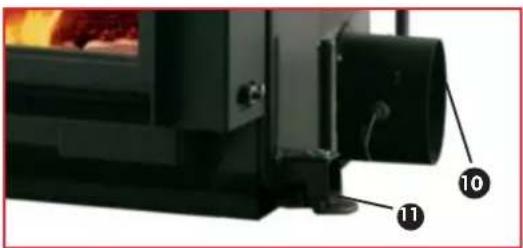
fig.4
natural_image
Metal bracket component with two notches and a numbered label (8) pointing to the top edge (no text or symbols on the part itself)natural_image
Mechanical device with labeled component A, shown from top (fig.6) with no visible text or symbols on the device itself.natural_image
Mechanical component with black shaft and flange, no visible text or symbolsnatural_image
Mechanical component with threaded shaft and flange, labeled 'fig.8' (no text or symbols on the object itself)natural_image
Technical line drawing of a mechanical assembly with two labeled components (A), no text or symbols present.natural_image
Technical line drawing of a mechanical device with mounting holes and structural supports (no text or symbols)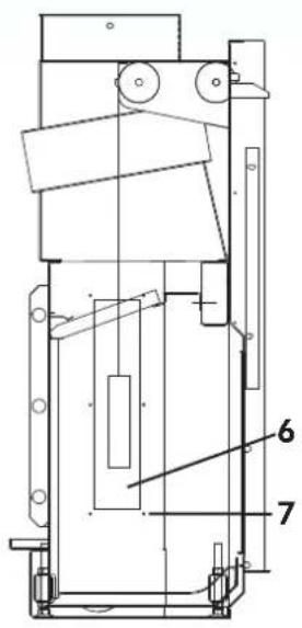
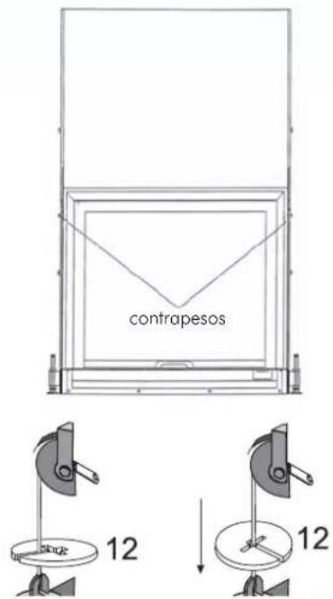
fig.11
natural_image
Diagram of airflow or ventilation system inside a room with pipes and control panel (no text or symbols)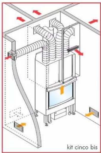
natural_image
Simple black outline of a mechanical lever or clamp (no text or symbols)mano fría
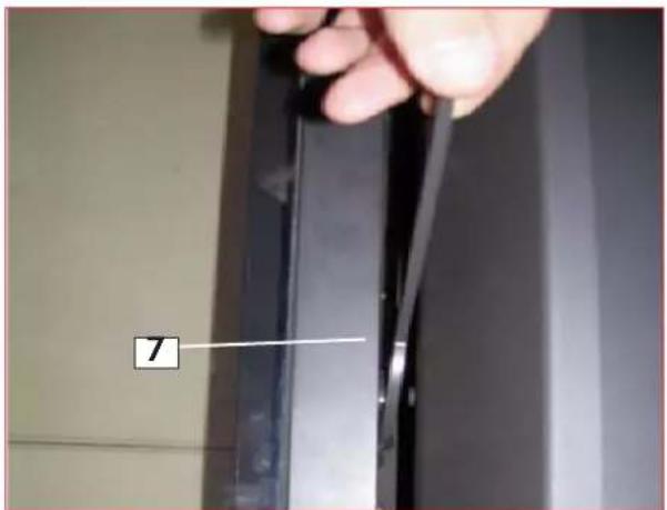
Figura 4 : bloqueo puerta cerrada (girar el trinquete 90°)
Abb. 1
natural_image
Interior view of a room with vertical slats and a wall-mounted shower structure (no text or symbols visible)Abb. 2
natural_image
Close-up of a metal shelf with a numbered label '14' pointing to a textured surface (no readable text or symbols)Abb. 3
natural_image
Close-up of a black industrial machine with labeled components (10 and 11), no visible text or symbols beyond labelsAbb. 4
LEGENDE: (Abb. 1-2-3-4-5)
natural_image
Metal bracket component with two notches and a numbered label (8) pointing to the top edge (no text or symbols on the part itself)Abb. 5
ABMESSUNGEN
natural_image
Mechanical device with labeled component A, no visible text or symbols on the device itself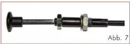
natural_image
Mechanical component with black shaft, flange, and bolted joint (no visible text or symbols)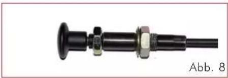
natural_image
Mechanical component with black shaft and bolts, labeled Abb. 8 (no text or symbols on the object itself)Verbrennungsluft
natural_image
Technical line drawing of a mechanical assembly with two labeled components (A), no text or symbols present.natural_image
Technical line drawing of a mechanical device with mounting holes and structural supports (no text or symbols)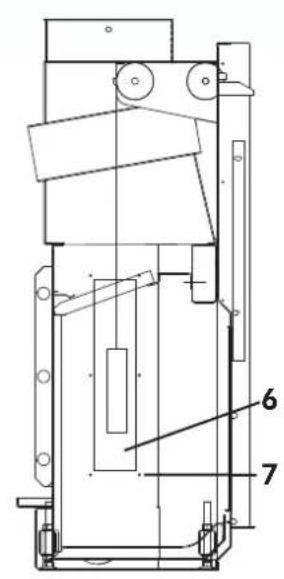
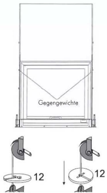
Abb.11
natural_image
Simple black outline of a wrench tool (no text or symbols)Kalte Hand
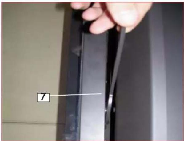
Abbildung 4: Geschlossene Türsperre (die Knagge um 90° drehen)
Afb.1
natural_image
Interior view of a room with a wall-mounted shower structure and a numbered label (6), no visible text or symbols.Afb. 2
natural_image
Close-up of a metal shelf with a numbered label '14' pointing to a specific area (no text or symbols on the shelf itself)Afb. 3
natural_image
Close-up of a black industrial machine with labeled components (10 and 11), no visible text or symbols beyond labels.Afb. 4
LEGENDE: (Afb. 1-2-3-4-5)
natural_image
Metal bracket with two notches and a numbered label (8) pointing to the side (no text or symbols on the bracket itself)Afb. 5
AFMETINGENAFMETINGEN
FLAT 120
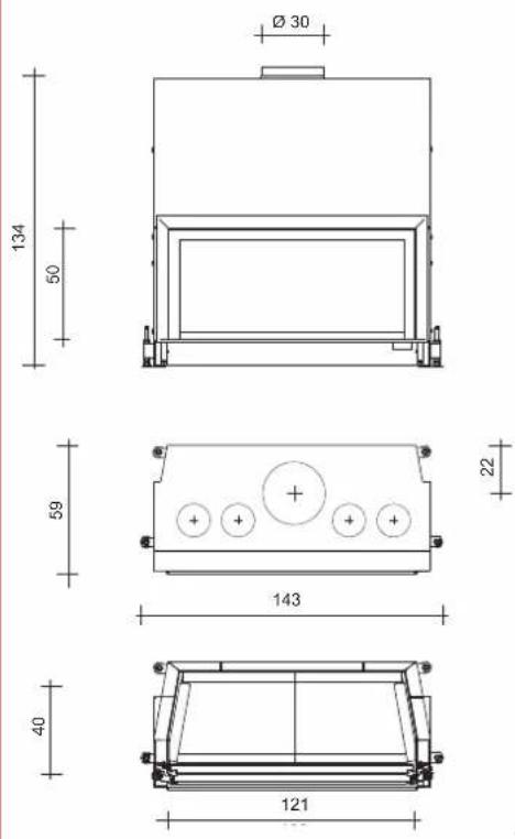
| Technische gegevens | |||
| FLAT 100 FLAT 120 | |||
| Nuttig vermogen kW 10,5 13 | |||
| Houtverbruik kg/h 3 3,8 | |||
| Rendement % 75 75 | |||
| Uitgang rookgassen ∅ cm 25 30 | |||
| Luchttoevoer ∅ cm 12,5 * | 12,5 * | ||
| Gewicht met verpakking | kg | 350 | 367 |
| Verwarmbaar volume | m3 | 275 | 340 |
natural_image
Mechanical device labeled 'A' with no visible text or symbols on the body itself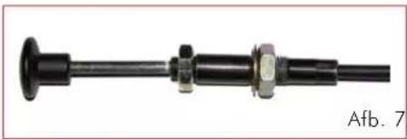
natural_image
Mechanical component with flanged shaft and bolted joint (no visible text or symbols)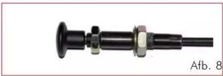
natural_image
Mechanical component with black shaft and bolts, no visible text or symbolsnatural_image
Technical line drawing of a mechanical assembly with two labeled components (A), no text or symbols present.INSTRUCTIES VOOR DE INSTALLATIEN
Rookgaskanaal
natural_image
Technical line drawing of a mechanical device with mounting holes and structural supports (no text or symbols)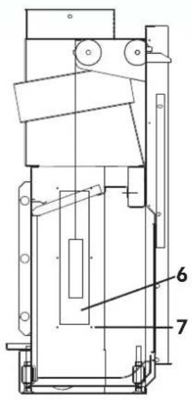
Afb. 11
INSTRUCTIES VOOR DE INSTALLATIEGEN
KIT KANALISATIE LUCHT
NEDERLANDS
natural_image
Simple black line drawing of a mechanical lever or clamp (no text or symbols)koude hand 7a
Figuur 4: vergrendeling gesloten deur (verankering 90° draaien)
εικ. 1
natural_image
Interior view of a room with vertical slats and a decorative wall fixture (no text or symbols visible)εικ. 2
natural_image
Close-up of a metal shelf with a numbered label '14' and a black arrow pointing to a specific area (no readable text or symbols beyond the number)EIK. 3
EIK. 4

natural_image
Metal bracket component with two notches and a numbered label (8) pointing to the side (no text or symbols on the part itself)εικ. 5
natural_image
Mechanical device labeled 'A' with no visible text or symbols on the body itself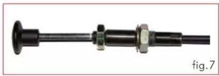
natural_image
Mechanical component with black shaft and bolted joint, no visible text or symbols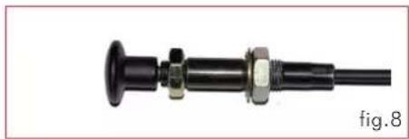
natural_image
Mechanical component with black shaft and bolts, no visible text or symbolsΑέρας καύσης
natural_image
Technical line drawing of a mechanical assembly with two labeled components A (no text or symbols beyond labels)natural_image
Technical line drawing of a mechanical device with mounting holes and structural supports (no text or symbols)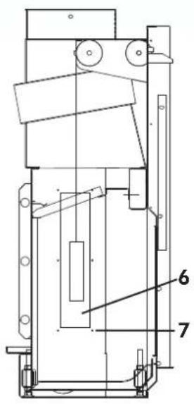
EIK.11
natural_image
Simple 3D diagram of a rectangular frame with a labeled section 'A' (no other text or symbols)natural_image
Diagram of airflow or ventilation system inside a room with pipes and control panel (no text or symbols)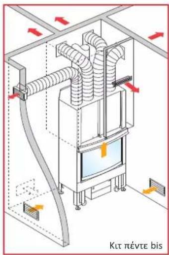
natural_image
Simple line drawing of a mechanical tool or bracket (no text or symbols)κρύο χέρι 7α

- Valvola a farfalla
- Safety information
- Important note
- THE FEATURES
- Removable handle for opening the door
- Internal covering of the hearth (fig. 2)
- LEGEND: (figs. 1-2-3-4-5)
- DIMENSIONI
- THE TECHNOLOGY
- Air for combustion
- Throttle valve
- Adjusting the throttle valve
- The air that is to be heated
- - natural convection
- - forced ventilation
- INSTALLATION INSTRUCTIONS
- Important Notices
- Premise
- Protecting the premises
- Warm air outlets / Grilles
- Thermal insulation
- Decorative beams
- The floor in front of the hearth
- Within the hearth's radiation range
- Out of the radiation range
- Power lines
- Handling rings.
- Smoke channel
- Chimney flue and chimneypot
- The fundamental characteristics of the chimney flue are:
- The fundamental characteristics of the chimney pot are:
- INSTALLING COUNTERBALANCES
- PROCEDURE (fig. 11):
- Finishing frame of the fireplace opening
- AIR-CHANNELLING KIT
- INSTRUCTIONS FOR USE
- Combustible material and calorific power
- Radiation range
- Initial start-up
- Burn hazards
- Air grilles
- Operating the hearth with the door open
- Adding combustible material
- Operating the fireplace in mid-season
- Air inflow in the room where the hearth is installed
- Lighting a cold hearth
- Adding firewood to a hot hearth
- Another suggestion:
- Removing the ashes
- CLEANING AND MAINTENANCE
- Cleaning the fireplace
- Cleaning the glass
- INSTRUCTIONS POUR L'INSTALLATION
- KIT CANALISATION AIR
- ABMESSUNGEN
- Verbrennungsluft
- LEGENDE: (Afb. 1-2-3-4-5)
- AFMETINGENAFMETINGEN
- INSTRUCTIES VOOR DE INSTALLATIEN
- Rookgaskanaal
- INSTRUCTIES VOOR DE INSTALLATIEGEN
- KIT KANALISATIE LUCHT
- Αέρας καύσης
Brand : EDILKAMIN
Model : DOUBLE
Category : Fireplace