
ZENIT P 130 - Lamp Cameo - Free user manual and instructions
Find the device manual for free ZENIT P 130 Cameo in PDF.

| Product type | LED PAR projector for outdoor use |
| Brand | Cameo |
| Model | ZENIT P 130 (CLZP130LSD) |
| LED type | 4 x 32 W RGBW |
| Beam angle | 8° (without diffuser), 25° and 45° diffusers included |
| Luminous flux | 2398 lumens (RGBW) |
| Illuminance at 1 m | 92600 lux (without diffuser) |
| Refresh rate | 3600 Hz |
| Control | DMX-512, RDM, infrared remote control |
| DMX modes | 2, 3, 4, 8 (x2), 10, 15 channels |
| Stand-alone functions | Auto, Color Macro, Static, Tunable White, User Color, Master/Slave |
| Power supply | 100-240 V, 50/60 Hz |
| Power consumption | 155 W |
| Protection rating | IP65 |
| Dimensions (WxHxD) | 192 x 187 x 187 mm (without bracket) |
| Weight | 4.8 kg |
| Housing material | Metal |
| Cooling | Convection |
| Operating temperature | -15°C to +45°C |
| Delivery contents | IP65 power cable, mounting bracket, 25° and 45° diffusers, infrared remote control |
| Cleaning | Dry cloth |
| Minimum distance to flammable materials | 0.5 m |
Frequently Asked Questions - ZENIT P 130 Cameo
User questions about ZENIT P 130 Cameo
0 question about this device. Answer the ones you know or ask your own.
Ask a new question about this device
Download the instructions for your Lamp in PDF format for free! Find your manual ZENIT P 130 - Cameo and take your electronic device back in hand. On this page are published all the documents necessary for the use of your device. ZENIT P 130 by Cameo.
USER MANUAL ZENIT P 130 Cameo
natural_image
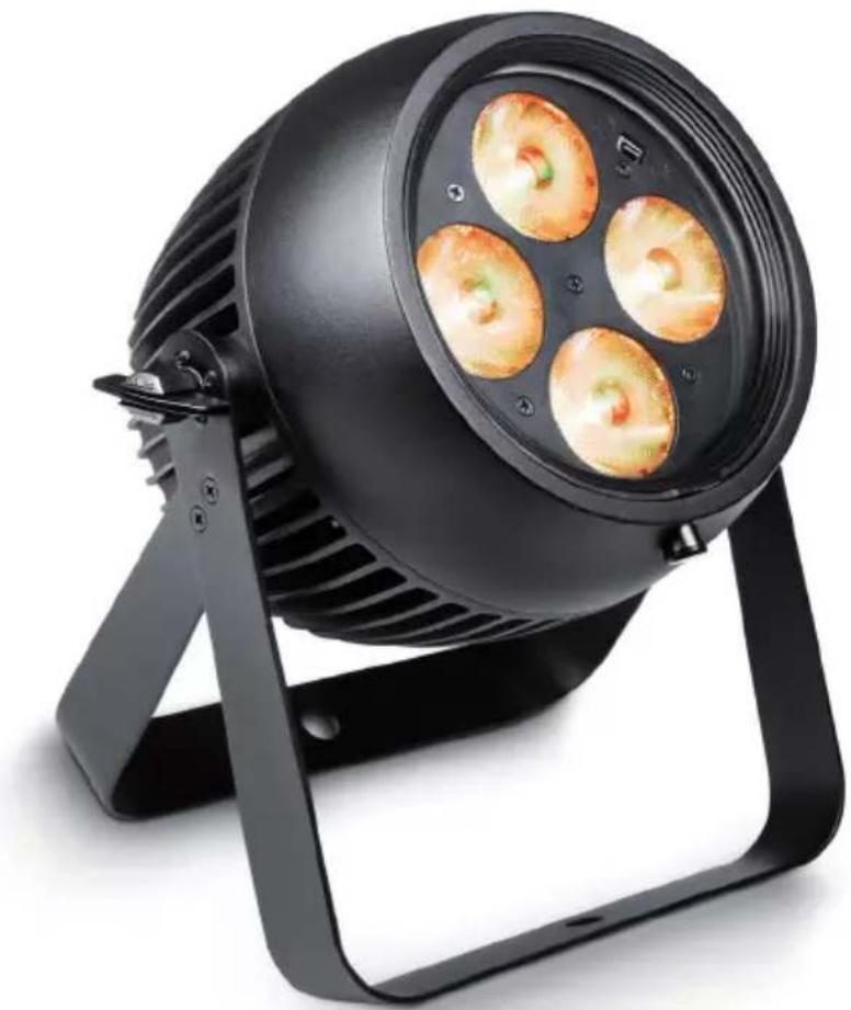
Black adjustable lighting fixture with four circular light fixtures mounted on a stand (no text or symbols visible)ZENIT P 40 / ZENIT P 130
PROFESSIONAL OUTDOOR PAR IP65 WITH INNOVATIVE LIGHT SHAPING DIFFUSORS
CLZP40LSD / CLZP130LSD
EN You've made the right choice!
We have designed this product to operate reliably over many years. Please read this User's Manual carefully, so that you can begin making optimum use of your Cameo Light product quickly. Learn more about Cameo Light on our website WWW.CAMEOLIGHT.COM.
- Please read these instructions carefully.
- Keep all information and instructions in a safe place.
- Follow the instructions.
- Observe all safety warnings. Never remove safety warnings or other information from the equipment.
- Use the equipment only in the intended manner and for the intended purpose.
- Use only sufficiently stable and compatible stands and/or mounts (for fixed installations). Make certain that wall mounts are properly installed and secured. Make certain that the equipment is installed securely and cannot fall down.
- During installation, observ e the applicable safety regulations for your country.
- Never install and operate the equipment near radiators, heat registers, ovens or other sources of heat. Make certain that the equipment is always installed so that is cooled sufficiently and cannot overheat.
- Never place sources of ignition, e.g., burning candles, on the equipment.
- Ventilation slits must not be blocked.
- This appliance is designed exclusively for indoor use, do not use this equipment in the immediate vicinity of water (does not apply to special outdoor equipment - in this case, observe the special instructions noted below). Do not expose this equipment to flammable materials, fluids or gases.
- Make certain that dripping or splashed water cannot enter the equipment. Do not place containers filled with liquids, such as vases or drinking vessels, on the equipment.
- Make certain that objects cannot fall into the device.
- Use this equipment only with the accessories recommended and intended by the manufacturer.
- Do not open or modify this equipment.
- After connecting the equipment, check all cables in order to prevent damage or accidents, e.g., due to tripping hazards.
- During transport, make certain that the equipment cannot fall down and possibly cause property damage and personal injuries.
- If your equipment is no longer functioning properly, if fluids or objects have gotten inside the equipment or if it has been damaged in anot her way, switch it off immediately and unplug it from the mains outlet (if it is a powered device). This equipment may only be repaired by authorized, qualified personnel.
- Clean the equipment using a dry cloth.
- Comply with all applicable disposal laws in your country. During disposal of packaging, please separate plastic and paper/cardboard.
- Plastic bags must be kept out of reach of children.
FOR EQUIPMENT THAT CONNECTS TO THE POWER MAINS:
- CAUTION: If the power cord of the device is equipped with an earthing contact, then it must be connected to an outlet with a protective ground. Never deactivate the protective ground of a power cord.
- If the equipment has been exposed to strong fluctuations in temperature (for example, after transport), do not switch it on immediately. Moisture and condensation could damage the equipment. Do not switch on the equipment until it has reached room temperature.
-
Before connecting the equipment to the power outlet, first verify that the mains voltage and frequency match the values specified on the equipment. If the equipment has a voltage selection switch, connect the equipment to the power outlet only if the equipment values and the mains power values match. If the included power cord or power adapter does not fit in your wall outlet, contact your electrician.
-
Do not step on the power cord. Make certain that the power cable does not become kinked, especially at the mains outlet and/or power adapter and the equipment connector.
- When connecting the equipment, make certain that the power cord or power adapter is always freely accessible. Always disconnect the equipment from the power supply if the equipment is not in use or if you want to clean the equipment. Always unplug the power cord and power adapter from the power outlet at the plug or adapter and not by pulling on the cord. Never touch the power cord and power adapter with wet hands.
- Whenever possible, avoid switching the equipment on and off in quick succession because otherwise this can shorten the useful life of the equipment.
- IMPORTANT INFORMATION: Replace fuses only with fuses of the same type and rating. If a fuse blows repeatedly, please contact an authorised service centre.
- To disconnect the equipment from the power mains completely, unplug the power cord or power adapter from the power outlet.
- If your device is equipped with a Volex power connector, the mating Volex equipment connector must be unlocked before it can be removed. However, this also means that the equipment can slide and fall down if the power cable is pulled, which can lead to personal injuries and/or other damage. For this reason, always be careful when laying cables.
- Unplug the power cord and power adapter from the power outlet if there is a risk of a lightning strike or before extended periods of disuse.
- The device must only be installed in a voltage-free condition (disconnect the mains plug from the mains).
- Dust and other debris inside the unit may cause damage. The unit should be regularly serviced or cleaned (no guarantee) depending on ambient conditions (dust etc., nicotine, fog) by qualified personnel to prevent overheating and malfunction.
- Please keep a distance of at least 0.5 m to any combustible materials.
- Power cables to power multiple devices must have a cross-section of at least 1.5 mm^2 . Within the EU, the cables must correspond to H05VV-F, or similar. Suitable cables are offered by Adam Hall. With these cables, you can connect multiple devices via the power OUT connection to the power IN connection of an additional device. Make sure that the total current consumption of all connected devices does not exceed the specified value on all connected devices (label on the device). Make sure to keep power cable connections as short as possible.

CAUTION:
To reduce the risk of electric shock, do not remove cover (or back). There are no user serviceable parts inside. Maintenance and repairs should be exclusively carried out by qualified service personnel.

The warning triangle with lightning symbol indicates dangerous uninsulated voltage inside the unit, which may cause an electrical shock.
The warning triangle with exclamation mark indicates important operating and maintenance instructions.

Warning! This symbol indicates a hot surface. Certain parts of the housing can become hot during operation. After use, wait for a cool-down period of at least 10 minutes before handling or transporting the device.
CAUTION! HIGH VOLUMES IN AUDIO PRODUCTS!
This device is meant for professional use. Therefore, commercial use of this equipment is subject to the respectively applicable national accident prevention rules and regulations. As a manufacturer, Adam Hall is obligated to notify you formally about the existence of potential health risks. Hearing damage due to high volume and prolonged exposure: When in use, this product is capable of producing high sound-pressure levels (SPL) that can lead to irreversible hearing damage in performers, employees, and audience members. For this reason, avoid prolonged exposure to volumes in excess of 90 dB.
CAUTION! IMPORTANT INFORMATION ABOUT LIGHTING PRODUCTS!
- The product has been developed for professional use in the field of event technology and is not suitable as household lighting.
- Do not stare, even temporarily, directly into the light beam.
- Do not look at the beam directly with optical instruments such as magnifiers.
- Stroboscope effects may cause epileptic seizures in sensitive people! People with epilepsy should definitely avoid places where strobes are used.
2-channel, 3-channel, 4-channel, 8-channel 1, 8-channel 2, 10-channel, and 15-channel DMX control
Master / Slave mode
Standalone Functions
IR remote control
FEATURES:
DMX 512, RDM enabled, High-Power RGBW LEDs, Stroboscope, 16-bit Dimmer, 4 Dimmer curves, Colour temperature correction, Fast access feature, IP65 Protection code, 5-pin DMX connectors, 25° and 45° diffuser screens and IR remote control supplied, mounting bracket included, operating voltage 100-240 V AC, power consumption 50 W (CLZP40LSD) or 155 W (CLZP130LSD).
OPERATION:
The Cameo ZENIT P40 and P130 are DMX-512-controllable outdoor projectors and can be operated as a Standalone device, in Master/Slave mode and via IR remote control. Furthermore, the spotlights are compliant with the RDM standard (Remote Device Management). This remote management system allows the status query and configuration of RDM devices via an RDM enabled controller.
DE Einführung
LED PAR IP65 RGBW
CLZP40LSD
LED PAR IP65 RGBW
CLZP130LSD
FOCO PAR LED IP65 RGBW
CLZP40LSD
FOCO PAR LED IP65 RGBW
CLZP130LSD
MODOS DE CONTROL:
Control DMX de 2 canales, 3 canales, 4 canales, 8 canales (1), 8 canales (2), 10 canales y 15 canales
Modo Maestro/Esclavo
Modos Autónomo
EN IEC power socket with rubber sealing cap. Operating voltage 100 - 240 V AC / 50 - 60 Hz. Connection via the supplied power cable (when not in use, always put the rubber sealing cap back on).
EN IP65 power output socket with rubber sealing cap. Used to supply power to additional CAMEO spotlights. Make sure that the total current consumption in amperes (A) of all connected devices does not exceed the specified value on the device (when not in use, always put the rubber sealing cap back on).
EN 5-pin male IP65 XLR socket for connection of a DMX controller (e.g. DMX console, when not in use, always put the rubber sealing cap back on).
EN 5-pin female IP65 XLR socket for connection of a DMX control signal (when not in use, always put the rubber sealing cap back on).
EN Displays the current operating mode and other system settings.
EN MODE - Pressing the MODE button will take you to the selection menu for system settings. Repeatedly pressing MODE takes you back to the main display. ENTER - Pressing the ENTER button takes you to the menu level to make changes in the values and to access one of the sub-menus. Confirm the value changes by pressing ENTER again. UP and DOWN - Selecting the individual menu items in the selection menu (DMX address, operating mode, etc.) and the sub-menus. Allows you to change the value of a menu item, such as the DMX address, as required.
EN Overhead installation should only be carried out by trained personnel. The spotlight must be secured with an appropriate safety cable to the safety eyelet to prevent falling.
EN Pressure compensation element to avoid condensation build-up inside the housing. To ensure proper operation, protect the element against contamination.
EN NOTES: To ensure splash water protection for the DMX sockets according to the IP65 protection class, the special DMX input and output sockets must be correctly closed with the special IP65 XLR plugs, or the rubber sealing caps must be used for sealing. The mains sockets POWER IN and POWER OUT, when correctly sealed, are protected against splash water according to IP65, as well as when the rubber sealing cap is correctly used.
- When the spotlight is properly connected to the mains, "Welcome to Cameo", the model name and software version appear successively on the display during the start-up process. After this operation, the spotlight is ready for use and starts in the mode that was previously selected.
- If one of the DMX operating modes is activated and there is no DMX signal at the DMX input, the currently selected DMX address is displayed and the characters on the display will start to flash.
- After approximately 1 minute of inactivity, the display will show the currently enabled operating mode.
- Fast Access Feature: In order to simplify the menu guide, the device has an intelligent menu structure which allows menu and sub-menu items that were last selected to be accessed directly. 1. Pressing MODE and ENTER simultaneously will take you directly to the sub-menu item that was last edited and allows you to instantly change the corresponding value as desired (DMX start address and all operating modes). 2. Pressing MODE will take you directly to the menu item that was last selected and edited; now press ENTER again to access the sub-menu items to adjust individual settings (DMX start address and all operating modes).
- Before changing device settings, ensure that the operating unit is dry and free of dust, so as not to impair its functionality.
- The display can be rotated by 180^ by pressing UP, as soon as the main screen is shown in the display.
CONFIGURE DMX START ADDRESS (DMX Address)
Press MODE to access the device settings selection menu (--- Menu ---). Use UP and DOWN to select the menu item "DMX Address" (observe arrow) and confirm with ENTER. The display will show a three-digit number field and you can use UP and DOWN to configure the desired DMX start address (highest value depends on DMX mode). Confirm with ENTER and press MODE to return to the main display (in the example, "DMX address 001"). If there is no DMX control signal, the display characters will flash. Flashing stops as soon as a control signal is present.


flowchart
graph TD
    A["001"] --> B["DMX Address 001"]
    C["5xx"] --> B
CONFIGURE DMX MODE (DMX Mode)
Press MODE to access the device settings selection menu (--- Menu ---). Use UP and DOWN to select the menu item "DMX Mode" (observe arrow) and confirm with ENTER. In the submenu you can choose between the following DMX modes: "15CH", "10CH", "8CH 2", "8CH 1", "4CH", "3CH" and "2CH". Confirm your selection with ENTER. DMX tables with the channel assignments can be found in these instructions under DMX CONTROL.


CONFIGURE STANDALONE MODE
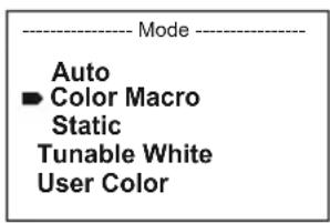
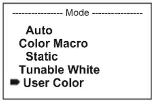
Press MODE to access the device settings selection menu (--- Menu ---). Use UP and DOWN to select the menu item "Stand Alone" (observe arrow) and confirm with ENTER. Now use UP and DOWN to select one of the following standalone modes: "Auto", "Color Macro", "Static", "Tunable White" and "User Color". Confirm your selection with ENTER.


AUTO MODE (Programme 1 - Programme 6)
The 6 different auto-programmes each comprise non-editable colour-change sequences. Brightness and speed are independently adjustable. Select auto mode as described above under CONFIGURE STANDALONE MODE and confirm with ENTER. Now use UP and DOWN to select one of the 6 auto programmes (observe arrow) and confirm with ENTER. To adjust brightness, use UP and DOWN to select the menu item “Dim” and confirm with ENTER, then use UP and DOWN to select the desired value between 000 and 255. Confirm with ENTER. Set the run speed by selecting the menu item “Speed”, confirm with ENTER, then select the desired value between 001 and 100. Confirm with ENTER. Press MODE four times to return to the main display (Mode Auto).


COLOUR MACROS (Color Macro)
15 different preset colour macros are available. Select "Color Macro" as described above under CONFIGURE STANDALONE MODE and confirm with ENTER. Now use UP and DOWN to select the desired colour preset (observe arrow) and confirm with ENTER (Color Off = blackout). A three-digit figure is shown on the display and you can set the desired brightness on a scale from 000 to 1000 using UP and DOWN. Confirm with ENTER. Press MODE three times to return to the main display (Color Macro Mode).


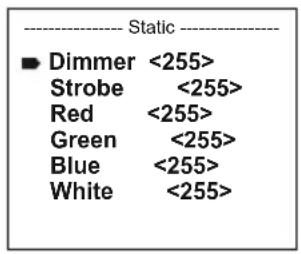
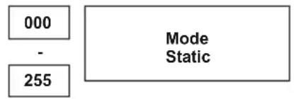
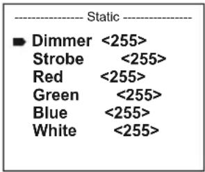
STATIC MODE (Static)
Static mode allows the functions Dimmer, Strobe and R, G, B, W to be adjusted directly on the device with values between 000 and 255, in a similar way to with a DMX controller. In this way, an individual scene can be created without an additional DMX controller. Select static mode as described above under CONFIGURE STANDALONE MODE and confirm with ENTER. Now use UP and DOWN to select the menu item you wish to edit (observe arrow) and confirm with ENTER. The display will show a three-digit number field and you can use UP and DOWN to configure the desired value between 000 and 255. Confirm with ENTER. Press MODE three times to return to the main display (Static Mode).


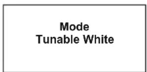
COLOUR TEMPERATURE (Tunable White)
Colour temperature mode enables the light to be configured with a colour temperature of cold white to warm white (CTC) and allows brightness (Dim) to be adjusted directly on the device. Select colour temperature mode as described above under CONFIGURE STANDALONE MODE and confirm with ENTER. Now use UP and DOWN to select the menu item you wish to edit (observe arrow) and confirm with ENTER. The display will show a three-digit number field and you can use UP and DOWN to configure the desired value. Confirm with ENTER. Press MODE three times to return to the main display (Tunable White Mode).


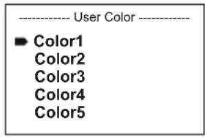
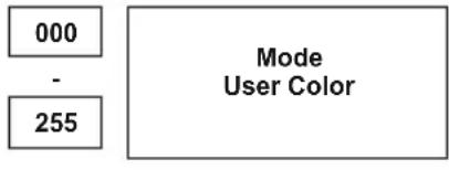
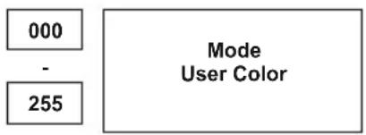
USER PRESETS (User Color)
User presets mode allows the overall brightness and a colour mixture of R, G, B and W to be saved directly in the device in five individual colour presets. Select "User Color" as described above under CONFIGURE STANDALONE MODE and confirm with ENTER. Now use UP and DOWN to select presets Color1 to Color5, confirm with ENTER and select the submenu item you would like to edit (observe arrow). Confirm with ENTER. The display will show a three-digit number field and you can use UP and DOWN to configure the value between 000 and 255 as required. Confirm again with ENTER. Once all settings have been made according to preference, press MODE four times to return to the main display (User Color Mode).

CONFIGURE SLAVE MODE
Press MODE to access the device settings selection menu (--- Menu ---). Use UP and DOWN to select the menu item "Slave" (observe arrow) and confirm with ENTER. Connect the slave and master units (same model) with a DMX cable and enable one of the standalone modes on the master unit (Auto, Colour Macro, Static, Tunable White, User Color). The slave unit will now follow the master unit. If there is no control signal, the display characters will flash. Flashing stops as soon as a control signal is present.


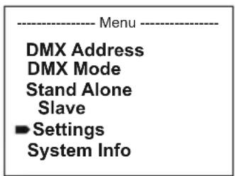
DEVICE SETTINGS (Settings)
Pressing MODE will take you to the selection menu for system settings (--- Menu ---). Using UP and DOWN, select the menu item "Settings" (observe the arrow) and confirm with ENTER.
You will then be taken to the sub-menu to set the following sub-menu items:
| Settings | ||||
| Display Reverse = Flip | Display | Play On = Rotation of the display by 180° (e.g. overhead installation) | ||
| Display Backlight = Display | display | lighting On = permanently on | ||
| Off = deactivation | on after approx. 1 minute of inactivity | |||
| DMX Fail = Operation status with DMX signal interruption | Hold = last command is held | |||
| Blackout = activates Blackout | ||||
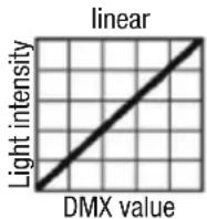
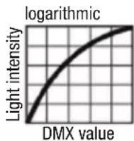
| Dimmer Curve = Dimmer Curve | Curve | Linear = The light intensity increases linearly with the DMX value | ||
| Dimmer Response | = | Dimmer response | Led | = The spotlight responds abruptly to changes in the DMX value |
| Halogen | = The spot behaves in a manner similar to that of a halogen lamp with gentle changes in brightness | |||
| Color Calibration | = Colour calibration | Red, Green, Blue, White | = individual colour calibration. Cross-operating mode brightness setting of 4 RGBW LED groups with values ranging from 000 to 255. | |
| Autolock | = automatic locking of the control elements | On = automatic locking of the control elements after 1 minute of inactivity. Display shows: "Locked!" Unlock: simultaneously press UP and DOWN for about 5 seconds | ||
| Off = automatic locking of the control elements is deactivated | ||||
| IR Remote = enable / disable operation via IR remote control | On = functionality enabled | |||
| Off = functionality disabled | ||||
| Factory Reset | = | Reset to factory setting | Reset to factory settings: ENTER -> "Reset Now! -> ENTER | |
Confirm all inputs with ENTER.
DIMMER CURVES


SYSTEM INFORMATION (System Info)
Pressing MODE will take you to the selection menu for system settings (--- Menu ---). Using UP and DOWN, select the menu item "System Info" (observe the arrow) and confirm with ENTER.
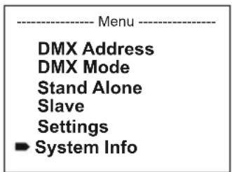
The required sub-menu can be selected as desired by using UP and DOWN in order to show the corresponding information by pressing ENTER.
| System Info | ||||
| Firmware | = | Displays the Firmware version Main CPU | Vx.x | |
| Temperature | = | Temperature display of the LED unit | LED | xx°C / xx°F |
| Unit | °C (= display in degrees Celsius) | |||
| °F (= display in degrees Fahrenheit) | ||||
| Operation Hours | = | Operating time display | xx:xxh | Displays the operating time in hours and minutes |
MANUAL LOCKING FUNCTION
In addition to the ability to protect the spotlight automatically against accidental or unauthorised operation (see "Settings" - "Autolock"), this function can also be carried out manually. Press UP and DOWN simultaneously for approx. 5 seconds. The display now shows "Locked!" if you try to change the settings, and it is no longer possible to make changes using the control panel. After approximately 1 minute, the display will show the currently enabled operating mode. To unlock, press UP and DOWN simultaneously for approx. 5 seconds. Now the display will change to the previously displayed information.
DE ANMERKUNGEN
FARBTEMPERATUR (Tunable White)
BENUTZER-PRESETS (User Color)


MACROS DE COULEUR (Color Macro)


| Mode |
| Auto Color Macro Static Tunable White User Color |
MODO AUTOMÁTICO (Program 1 - Program 6)
| Auto |
| Program 1 |
| Program 2 |
| Program 3 |
| Program 4 |
| Program 5 |
| Program 6 |
| Program x | |
| Dim <255>Speed <100> | |
| Dim | Speed |
| 000 | 001 |
| - | - |
| 255 | 100 |
| ModeAuto |
| 000- | 001- |
| 255 | 100 |
MACROS DE COLOR (Color Macro)
| Mode |
| Auto |
| Color Macro |
| Static |
| Tunable White |
| User Color |
| Color Macro | |
| ■ Color Off | |
| Red | <100> |
| Amber | <100> |
| Yellow Warm | <100> |
| Yellow | <100> |
| Green | <100> |
| Turquoise | <100> |
| Cyan | <100> |
| Blue | <100> |
| Lavender | <100> |
| Mauve | <100> |
| Magenta | <100> |
| Pink | <100> |
| Warm White | <100> |
| White | <100> |
| Cold White | <100> |
| 000 |
| - |
| 100 |
MODO ESTÁTICO (Static)
flowchart
graph TD
    A["000"] --> C["Mode Static"]
    B["255"] --> C["Mode Static"]
TEMPERATURA DE COLOR (Tunable White)
PRESETS DE USUARIO (User Color)

AJUSTE DEL MODO ESCLAVO
TRYB PRACY AUTO (program 1 – program 6)


MAKRA KOLORÓW (Color Macro)


TRYB STATYCZNY (Static)

TEMPERATURA BARWOWA (Tunable White)
WSTĘPNE USTAWIENIA UŻYTKOWNIKA (User Color)


USTAWIANIE TRYBU PRACY SLAVE


| Mode Auto |
MACRO COLORI (Color Macro)


FARBTEMPERATUR (Tunable White)
BENUTZER-PRESETS (User Color)


| Aim the infrared remote control directly at the infrared sensor on the front of the lamp. The maximum range is approximately 8 metres. In DMX and Slave modes, the remote control is deactivated. Battery for IR remote control = CR2025. | ||
| Blackout | The blackout button is used to switch off all LEDs, regardless of operating mode enabled via the remote control. Press the blackout button again to reactivate the previously selected mode. | |
| Auto-programme | Auto-Programmes 1 - 6. Programme selection with + and -gramme run speed with SPEED and +. Brightness setting with % and +. - | |
| Color macros | Color macros 1 - 15. Selection with + and - | |
| Strobe | Strobe light for AUTO, FADE and MANUAL operating modes. Press STROBE to activate. Strobe speed with + and - stress to fade strobe. | |
| Speed | Setting the running speed for Auto and Fade programmes. | |
| Individual color macros | Individual color macros 1 - 5. Select with + and - | |
| Brightness | Press % and + to adjust brightness. | |
| Manual colour mix | Press MANUAL and , for to manually mix colours. Adjust intensity with + and - | |
 | Fade programmes | Fade programmes Auto 1 - Auto 5. Programme selection with + and - . Programme run speed with SPEED and . Rightness cutting with % and + . - |
 | Colour preset | Direct selection of colour presets 0 to 9. |
DMX (Digital Multiplex) is the designation for a universal transmission protocol for communications between corresponding devices and controllers. A DMX controller sends DMX data to the connected DMX device(s). The DMX data is always transmitted as a serial data stream that is forwarded from one connected device to the next via the "DMX IN" and "DMX OUT" connectors (XLR plug-type connectors) that are found on every DMX-capable device, provided the maximum number of devices does not exceed 32 units. The last device in the chain needs to be equipped with a terminator (terminating resistor).

natural_image
Coiled black cable with two connectors and a terminal connector (no text or symbols visible)DMX CONNECTION
DMX is the common "language" via which a very wide range of types and models of equipment from various manufacturers can be connected with one another and controlled via a central
controller, provided that all of the devices and the controller are DMX compatible. For optimum data transmission, it is necessary to keep the connecting cables between the individual devices as short as possible. The order in which the devices are integrated in the DMX network has no influence on the addresses. Thus the device with the DMX address 1 can be located at any position in the (serial) DMX chain: at the beginning, at the end or somewhere in the middle. If the DMX address 1 is assigned to a device, the controller "knows" that it should send all data allocated to address 1 to this device regardless of its position in the DMX network.
SERIAL CONNECTION OF MULTIPLE LIGHTS
- Connect the male XLR connector (3-pin or 5-pin) of the DMX cable to the DMX output (female XLR socket) of the first DMX device (e.g. DMX-Controller).
- Connect the female 3-pin XLR connector of the DMX cable connected to the first projector to the DMX input (male 3-pin socket) of the next DMX device. In the same way, connect the DMX output of this device to the DMX input of the next device and repeat until all devices have been connected. Please note that as a rule, DMX devices are connected in series and connections cannot be shared without active splitters. The maximum number of DMX devices in a DMX chain should not exceed 32 units.
The Adam Hall 3 STAR, 4 STAR, and 5 STAR product ranges include an extensive selection of suitable cables.
DMX CABLES
When fabricating your own cables, always observe the illustrations on this page. Never connect the shielding of the cable to the ground contact of the plug, and always make certain that the shielding does not come into contact with the housing of the XLR plug. If the shielding is connected to the ground, this can lead to short-circuiting and system malfunctions.
Pin Assignment
DMX cable with 3-pin XLR connectors: DMX cable with 5-pin XLR connectors (pin 4 and 5 are not used):

flowchart
graph LR
    A["1"] --> B["Shield"]
    C["3"] --> B
    D["2"] --> B
    B --> E["1"]
    B --> F["3"]
    B --> G["2"]

DMX TERMINATORS (TERMINATING RESISTORS)
To prevent system errors, the last device in a DMX chain needs to be equipped with a terminating resistor (120 ohm, 1/4 Watt).
3-pin XLR connector with a terminating resistor: K3DMXT3
5-pin XLR connector with a terminating resistor: K3DMXT5
Pin Assignment
3-pin XLR connector: 5-pin XLR connector:


DMX ADAPTER
The combination of DMX devices with 3-pin connectors and DMX devices with 5-pin connectors in a DMX chain is possible with suitable adapters.
Pin Assignment
DMX Adapter 5-pin XLR male to 3-pin XLR female: K3DGF0020
Pins 4 and 5 are not used.
Pin Assignment
DMX Adapter 3-pin XLR male to 5-pin XLR female: K3DHM0020
Pins 4 and 5 are not used.


DE DMX-512
natural_image
Coiled black cable with two connectors and a terminal connector (no text or symbols visible)DMX-VERBINDUNG:
natural_image
Coiled black cable with two connectors and a three-pin connector (no text or symbols visible)PROTOCOLE DMX
natural_image
Coiled black cable with two connectors and a three-pin connector (no text or symbols visible)natural_image
Coiled black cable with two connectors and a terminal pin (no text or symbols visible)ZŁĄCZE DMX:
natural_image
Coiled black cable with two connectors and a three-pin connector (no text or symbols visible)COLLEGAMENTO DMX:
natural_image
Close-up of a black circular object with green lens and metallic rim, partially overlaid by a curved line (no text or symbols visible)
natural_image
Close-up of a black mechanical component with a knob and mounting holes (no visible text or symbols)
natural_image
Close-up of a black mechanical component with a knob, no visible text or symbolsEN Two diffuser screens with a different beam dispersion (1 x 25° identified by a notch on the edge, 1 x 45°) are supplied with the spotlight. The beam angle of the spotlight can thus be adjusted individually to 8° (without diffuser), or 45°. Set the desired screen (rough side towards the front glass) into the provided rubber frame, release the spring-loaded safety stud (pull the handle approx. 1cm outwards) as shown, place the screen onto the glass front of the spotlight and release the safety stud to let it click into place in the slot provided in the rubber frame.
DE Im Lieferumfang des Strahlers befinden sich zwei Streuscheiben, die über ein unterschiedliches Abstrahlverhalten verfügen (1x 25° zur Identifizierung mit Kerbe am Rand, 1x 45°). Der Abstrahlwinkel des Strahlers kann somit individuell auf 8° (ohne Streuscheibe), 25°, oder 45° verändert werden. Legen Sie die gewünschte Streuscheibe (raue Seite Richtung Frontglas) in den dafür vorgesehenen Gummirahmen, entriegeln den gefederten Sicherungsstift (am Griff ca. 1cm nach außen ziehen), setzen, wie abgebildet, die Streuscheibe vor das Frontglas des Scheinwerfers und lösen den Zug am Sicherungsstift, um ihn in der dafür vorgesehenen Vertiefung im Gummirahmen einrasten zu lassen.
FR Le projecteur est livré avec deux diffuseurs, pour obtenir un angle de départ différent (25°, répéré par une encoche sur le pourtour, ou 45°). Le projecteur permet donc d'obtenir trois angles de départ différents : 8° (sans diffuseur), 25° (diffuseur 1) ou 45° (diffuseur 2). Placez le diffuseur désiré (face rugueuse du côté de la glace avant) dans l'armature en caoutchouc prévue à cet effet, déverrouillez la goupille de sécurité sur ressort (tirez-la vers l'extérieur d'environ 1 cm), mettez en place le diffuseur sur la face avant du projecteur comme illustré, puis relâchez la goupille de sécurité : elle revient alors se loger dans le creux prévu à cet effet dans l'armature en caoutchouc.
ES Con el foco se suministran dos difusores que ofrecen dos tipos de ángulo de haz diferentes: 25° (identificable por la muesca en el borde) y 45°. Así, el ángulo de dispersión del foco se puede cambiar a 8° (sin difusor), a 25° o a 45°. Acople el difusor (con la cara rugosa hacia el frontal de cristal) en el marco de goma previsto al efecto, levante el pasador con muelle (1 cm aprox. hacia afuera), inserte el difusor, como se muestra en la figura, delante del frontal de cristal del foco y suelte el pasador para que se introduzca por el orificio del marco de goma.
PL W zestawie wraz z reflektorem znajdują się dwie osłony rozpraszające wyposażone w różne warianty emisji wiązki światła (1 x 25° w celu identyfikacji z nacięciem na krawędzi, 1 x 45°). Dzięki temu kąt wiązki światła można ustawić na 8° (bez osłony rozpraszającej), 25° lub 45°. Umieścić wybraną osłonę rozpraszającą (szorstką stronę w kierunku przedniej szybki) w gumowej ramce, odblokować sprężynę kołka zabezpieczającego (wysunąć za uchwyt na ok. 1 cm na zewnątrz), ustawić osłonę przed przednią szybką reflektora, jak przedstawiono na ilustracji, a następnie zwolnić napreżenie kołka zabezpieczającego, aby zablokował się on w przewidzianym do tego zagłębieniu w gumowej ramce.
IT Il faro è fornito di serie con due diffusori, ciascuno con diversa dispersione: 25° (identificabile per la tacca sul bordo) e 45°. L'angolo di dispersione del faro pertanto può essere impostato a piacere su 8° (senza diffusore), 25° o 45°. Collocare il dispersore prescelto (lato ruvido verso il vetro anteriore) nell'apposita guarnizione in gomma, sbloccare la sicura a molla (tirare la linguetta per circa 1 cm verso l'esterno), collocare il diffusore davanti al vetro del faro, come in figura, e allentare la presa sulla linguetta per inserirla nell'apposita sede della guarnizione in gomma.
SETTING UP AND MOUNTING / AUFSTELLUNG UND MONTAGE / MISE EN PLACE ET MONTAGE / INSTALACIÓN Y MONTAJE / USTAWIENIE I MONTAZ / INSTALLAZIONE E MONTAGGIO
natural_image
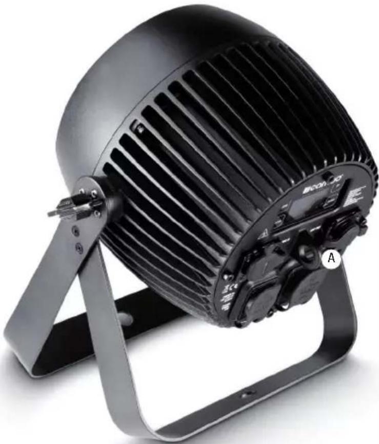
Black-framed air conditioner fan with adjustable arm and mounting bracket (no visible text or symbols)EN Thanks to the integrated double bracket, the spotlight can be placed in a suitable location on a flat surface. Mounting on a truss is performed with the help of a suitable truss clamp (not included). Make sure that the connection to the mounting bracket is solid, and secure the device with a suitable safety rope to the space provided (A). Important Notice: Overhead installation should only be carried out by trained personnel.
DE Dank des integrierten Doppelbügels kann der Scheinwerfer an einer geeigneten Stelle auf eine ebene Fläche gestellt werden. Die Montage an einer Traverse erfolgt mit Hilfe einer geeigneten Traversenklemme (nicht im Lieferumfang enthalten). Sorgen Sie für eine feste Verbindung am Montagebügel und sichern Sie den Scheinwerfer mit einem geeigneten Sicherungsseil an der dafür vorgesehenen Stelle (A). Wichtiger Hinweis: Überkopfmontage darf nur von dafür ausgebildetem Personal durchgeführt werden.
FR Grâce à son double support intégré, le projecteur peut être posé sur une surface plane, à l'endroit désiré. Le montage sur barre ou structure métallique s'effectue par l'intermédiaire d'une pince spécifique (non livrée). Vérifiez la solidité de la fixation du support de montage, et sécurisez l'appareil via une élingue de sécurité passée dans l'emplacement correspondant (A). Avertissement important : Le montage en hauteur doit être exclusivement effectué par du personnel spécialement formé.
ES Gracias al soporte doble integrado, el foco se puede instalar perfectamente sobre una superficie plana. Para montarlo en trusses, utilice una abrazadera adecuada (no suministrada). Para mayor seguridad, asegure el equipo introduciendo un cable de seguridad apropiado a través de la argolla prevista para tal efecto (A). Nota importante: El montaje suspendido sólo puede realizarse por personal experimentado.
PL Dzięki zintegrowanemu podwójnemu pałąkowi reflektor można ustawić w odpowiednim miejscu na równej płaszczyźnie. Do montażu na trawersie służy specjalny zacisk do trawersu (nie znajduje się w zestawie). Należy zadbać o stabilne połączenie z pałąkiem montażowym i zabezpieczyć reflektor odpowiednią liną zabezpieczającą we wskazanym miejscu (A). Ważna informacja: montaż nad głową może być wykonywany wyłącznie przez odpowiednio przeszkolony personel.
IT Grazie alla doppia staffa integrata, il faro può essere collocato in un punto adatto su una superficie piana. Per effettuare il montaggio su traversa, utilizzare un morsetto adatto (non in dotazione). Aver cura di fissare la staffa di montaggio saldamente e assicurare il faro facendo passare un cavo di sicurezza adatto dall'apposito punto (A). Nota importante: il montaggio sopratesta deve essere eseguito esclusivamente da personale qualificato.
SPECIFICATIONS / TECHNISCHE DATEN / CARACTÉRISTIQUES TECHNIQUES / CARACTERÍSTICAS TÉCNICAS / PRZYŁĄCZA, WYMIARY I MONTAŻ / DATI TECNICI
EN
| Model Name: CLZP40LSD | CLZP130LSD | |
| Product Type: | LED PAR LED PAR | |
| Type: | outdoor spotlight | outdoor spotlight |
| LED Colour Spectrum: | RGBW RGBW | |
| Number of LEDs: | 4 4 | |
| LED Type: | 10 W | 32 W |
| Refresh Rate: | 3600 Hz 3600 Hz | |
| Beam Angle: | 8° 8° | |
| DMX Input: 5-pin XLR male, IP65 | 5-pin XLR male, IP65 | |
| DMX Output: | 5-pin XLR female, IP65 | 5-pin XLR female, IP65 |
| DMX Mode: | 2-channel, 3-channel, 4-channel, 8-channel 1, 8-channel 2, 10-channel, 15-channel | 2-channel, 3-channel, 4-channel, 8-channel 1, 8-channel 2, 10-channel, 15-channel |
| DMX Functions: | Dimmer, Dimmer Fine, RGBW, RGBW Fine, Stroboscope, Dimmer Curves, Colour Temperature Correction, Dimmer Response, Colour Macros, Colour Blending, Colour Fading | Dimmer, Dimmer Fine, RGBW, RGBW Fine, Stroboscope, Dimmer Curves, Colour Temperature Correction, Dimmer Response, Colour Macros, Colour Blending, Colour Fading |
| Standalone Functions: | Colour Mixing, Colour Macros, Master/Slave Operation, Auto programs, Strobe, Dimmer Response, Dimmer Curves, Display Lock Function, Colour calibration | Colour Mixing, Colour Macros, Master/Slave Operation, Auto programs, Strobe, Dimmer Response, Dimmer Curves, Display Lock Function, Colour calibration |
| Control: | DMX512, RDM enabled, IR remote control | DMX512, RDM enabled, IR remote control |
| Controls: | Mode, Enter, Up, Down | Mode, Enter, Up, Down |
| Indicators: | OLED Display | OLED Display |
| Operating Voltage: | 100 - 240 V AC / 50 - 60 Hz | 100 - 240 V AC / 50 - 60 Hz |
| Power Consumption: | 50 W | 155 W |
| Illuminance (@ 1 m without diffuser screen): | 25,200 lx | 92,600 lx |
| Luminous Flux (RGBW): | 996 lm | 2398 lm |
| Power Connector: | Input and output, special IP65 sockets | Input and output, special IP65 sockets |
| Temperature (during operation): | -15°C - +45°C | -15°C - +45°C |
| Housing Material: | metal | metal |
| Housing Colour: | black | black |
| Housing Cooling: | convection | convection |
| IP Protection Class: IP65 IP65 | ||
| Dimensions (W x H x D, excluding bracket): | 192 x 187 x 187 mm | 192 x 187 x 187 mm |
| Weight: | 4.8 kg | 4.8 kg |
| Other Features: 1 m power cable with special IP65 plug, supplied stand/mounting bracket, 2 diffuser screens 25° and 45° and IR remote control included | 1 m power cable with special IP65 plug, supplied stand/mounting bracket, 2 diffuser screens 25° and 45° and IR remote control included | |
DE
You can find our current warranty conditions and limitations of liability at: http://www.adamhall.com/media/shop/downloads/documents/manufacturersdeclarations.pdf. To request warranty service for a product, please contact Adam Hall GmbH, Daimler Straße 9, 61267 Neu Anspach / Email: Info@adamhall.com / +49 (0)6081 / 9419-0. To enquire about the current declaration of conformity, please contact info@adamhall.com.
CORRECT DISPOSAL OF THIS PRODUCT
(Valid in the European Union and other European countries with a differentiated waste collection system) This symbol on the product, or on its documents indicates that the device may not be treated as household waste. This is to avoid environmental damage or personal injury due to uncontrolled waste disposal. Please dispose of this product separately from other waste and have it recycled to promote sustainable economic activity. Household users should contact either the retailer where they purchased this product, or their local government office, for details on where and how they can recycle this item in an environmentally friendly manner. Business users should contact their supplier and check the terms and conditions of the purchase contract. This product should not be mixed with other commercial waste for disposal.
FCC STATEMENT
This device complies with Part 15 of the FCC Rules. Operation is subject to the following two conditions:
(1) This device may not cause harmful interference, and
(2) This device must accept any interference received, including interference that may cause undesired operation
CE Compliance
Adam Hall GmbH states that this product meets the following guidelines (where applicable):
R&TTE (1999/5/EC) or RED (2014/53/EU) from June 2017
Low voltage directive (2014/35/EU)
EMV directive (2014/30/EU)
RoHS (2011/65/EU)
The complete declaration of conformity can be found at www.adamhall.com.
Furthermore, you may also direct your enquiry to info@adamhall.com.
natural_image
Stylized white letter 'J' on black background, enclosed in a rounded square frame (no text or symbols)WWW.CAMEOLIGHT.COM

- ZENIT P 40 / ZENIT P 130
- EN You've made the right choice!
- FOR EQUIPMENT THAT CONNECTS TO THE POWER MAINS:
- CAUTION:
- CAUTION! HIGH VOLUMES IN AUDIO PRODUCTS!
- CAUTION! IMPORTANT INFORMATION ABOUT LIGHTING PRODUCTS!
- FEATURES:
- OPERATION:
- FOCO PAR LED IP65 RGBW
- MODOS DE CONTROL:
- CONFIGURE DMX START ADDRESS (DMX Address)
- CONFIGURE DMX MODE (DMX Mode)
- CONFIGURE STANDALONE MODE
- AUTO MODE (Programme 1 - Programme 6)
- COLOUR MACROS (Color Macro)
- STATIC MODE (Static)
- COLOUR TEMPERATURE (Tunable White)
- USER PRESETS (User Color)
- CONFIGURE SLAVE MODE
- DEVICE SETTINGS (Settings)
- SYSTEM INFORMATION (System Info)
- MANUAL LOCKING FUNCTION
- DE ANMERKUNGEN
- FARBTEMPERATUR (Tunable White)
- BENUTZER-PRESETS (User Color)
- MACROS DE COULEUR (Color Macro)
- MODO AUTOMÁTICO (Program 1 - Program 6)
- MACROS DE COLOR (Color Macro)
- MODO ESTÁTICO (Static)
- TEMPERATURA DE COLOR (Tunable White)
- PRESETS DE USUARIO (User Color)
- AJUSTE DEL MODO ESCLAVO
- TRYB PRACY AUTO (program 1 – program 6)
- MAKRA KOLORÓW (Color Macro)
- TRYB STATYCZNY (Static)
- TEMPERATURA BARWOWA (Tunable White)
- WSTĘPNE USTAWIENIA UŻYTKOWNIKA (User Color)
- USTAWIANIE TRYBU PRACY SLAVE
- MACRO COLORI (Color Macro)
- DMX CONNECTION
- SERIAL CONNECTION OF MULTIPLE LIGHTS
- DMX CABLES
- Pin Assignment
- DMX TERMINATORS (TERMINATING RESISTORS)
- DMX ADAPTER
- DE DMX-512
- DMX-VERBINDUNG:
- PROTOCOLE DMX
- ZŁĄCZE DMX:
- COLLEGAMENTO DMX:
- SETTING UP AND MOUNTING / AUFSTELLUNG UND MONTAGE / MISE EN PLACE ET MONTAGE / INSTALACIÓN Y MONTAJE / USTAWIENIE I MONTAZ / INSTALLAZIONE E MONTAGGIO
- SPECIFICATIONS / TECHNISCHE DATEN / CARACTÉRISTIQUES TECHNIQUES / CARACTERÍSTICAS TÉCNICAS / PRZYŁĄCZA, WYMIARY I MONTAŻ / DATI TECNICI
- CORRECT DISPOSAL OF THIS PRODUCT
- FCC STATEMENT
- CE Compliance
Brand : Cameo
Model : ZENIT P 130
Category : Lamp