F-7 - Effect machine Antari - Free user manual and instructions
Find the device manual for free F-7 Antari in PDF.

| Product type | Smoke machine |
| Brand | Antari |
| Model | F-7 |
| Dimensions (L x W x H) | 728 x 428 x 719 mm |
| Weight | 52.5 kg |
| Power supply | AC 100-240 V, 50/60 Hz, 1600 W |
| Heating time | Approximately 6 minutes |
| Liquid consumption (fog mode) | 140 ml/min |
| Liquid consumption (haze mode) | 28 ml/min |
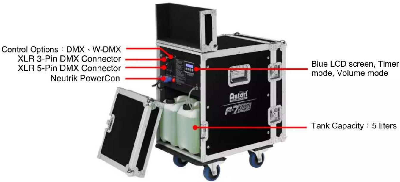
| Tank capacity | 5 liters |
| Compatible liquid | Antari FLG-5E Heavy Fog Fluid |
| Control | DMX512, timer, manual, W-DMX |
| DMX channels | 3 channels |
| Connectors | Neutrik PowerCon (power), XLR 3 and 5 pin (DMX) |
| Display | Blue LCD |
| Main functions | Timer (interval, duration, output), continuous volume mode, adjustable fan speed, automatic shutdown with cleaning |
| Safety | Overheating protection, automatic shutdown, minimum safety distance of 50 cm |
| Maintenance | Regular cleaning with distilled water, drain the tank before transport |
| Operating conditions | Indoor, ambient temperature 0°C to 40°C |
| Delivery contents | 1 machine, 2 power cables, 2 liquid tanks, 1 user manual |
| Warranty and support | Contact Antari dealer, no user-serviceable parts |
Frequently Asked Questions - F-7 Antari
User questions about F-7 Antari
0 question about this device. Answer the ones you know or ask your own.
Ask a new question about this device
Download the instructions for your Effect machine in PDF format for free! Find your manual F-7 - Antari and take your electronic device back in hand. On this page are published all the documents necessary for the use of your device. F-7 by Antari.
USER MANUAL F-7 Antari
natural_image
Exterior view of a black F7 Source air conditioner unit with open doors and fan (no visible text or symbols on the device itself)
CE


EAC
English • Français • Deutsch

User Manual - English
Safety Information

Please read the following safety information carefully before operating the machine. This information includes important safeguards about installation, usage, and maintenance. Pay attention to all warning labels and instructions in this manual and printed on the machine.
If you have questions about how to operate the machine safely, please contact your local Antari dealer for help.
- Keep this device dry.
• Always connect to a grounded circuit to avoid risk of electrocution. - Before connecting the machine to power, always check the voltage indicated on the machine matches to your local AC voltage. Do not use the machine if the AC power voltage does not match.
- Disconnect the machine from AC power before servicing and when not in use.
- This product is for indoor use only! Do not expose to rain or moisture. If fluid is spilled, disconnect AC power and clean with a damp cloth. If fluid is spilled onto electronic parts, immediately unplug the machine and contact your local Antari dealer for advice.
- No user serviceable and modifiable parts inside. Never try to repair this product, an unauthorized technician may cause damage or malfunction to the machine.
• For adult use only. Never leave the machine running unattended.
• Install the machine in a well-ventilated area. Provide at least 50 cm of space around the machine. - Never add flammable liquid of any kind to the machine.
• Make sure there are no flammable materials close to the machine while operating.
• Only use Antari fluid. Other fluid may lead to heater clog or malfunction.
- If the machine fails to work, unplug the machine and stop operation immediately. Contact your local Antari dealer for advice.
• Before transporting the machine, make sure the fluid tank is completely drained.
- Fog fluid may present health risks if swallowed. Do not drink fog fluid. Store it securely. In case of eye contact or if fluid is swallowed, immediately seek medical advice.
Unpacking and Inspection
Immediately upon receiving the machine, carefully unpack the carton, check the contents to ensure that all parts are present and have been received in good condition. If any parts appear damaged or mishandled from shipping, notify the shipper immediately and retain the packing material for inspection.
What is included: 1 x F-7 SMAZE Machine
2 x Power Cord (One for Fog Machine, the other for Fan)
2 x Fluid Tank
1 x User Manual
Product Dimensions
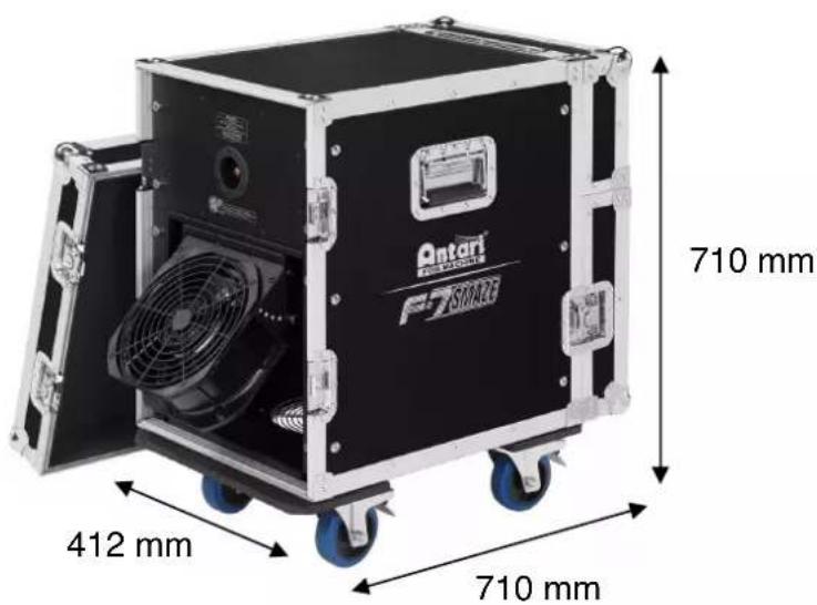
Product Overview
Setting Up
Step 1: Place the machine on a flat surface and in a suitably large area with at least 50 cm of open space around the machine.
Step 2: Fill the fluid tank with Antari approved fluid.
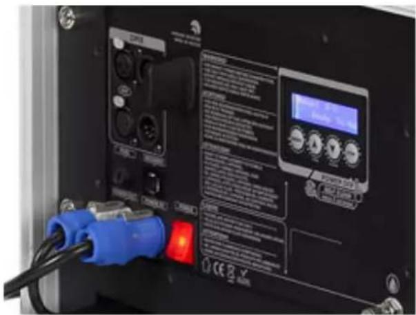
Step 3: Connect the machine to a suitably rated power supply. To determine the power requirement for the machine refer to the label on the machine.

Always connect the machine to a protected circuit and ensure it is properly grounded to avoid risk of electrocution.
Step 4: Turn on the machine and allow it to heat up. Heat up takes approximately 6 mintues. Once the machine has reached operating temperature, the display will show "Ready to Fog". Now the machine is ready for operation.
Step 5: To start making fog, press the VOLUME button on the control panel.
Step 6: To turn off the machine, hold the STOP button for 3 seconds; the machine will automatically run a self-cleaning process and shut down after the self-cleaning process is done.
Operation
Control Panel Operation
The machine can be operated with the onboard digital control interface.

| Button | Function |
| [MENU] | Scroll through setting menu |
| [UP]/[TIMER] | Up/Activate Timer function |
| [DOWN]/[VOLUME] | Down/Activate Volume function |
| [STOP] | Deactivate Timer/Volume function.Or to select and memorize the setting.Hold 3 seconds to start self-cleaning process and shut down the machine |
Control Menu
Operation Mode
XXXX
Select Fog or Faze Mode
Set interval time at Timer mode from 1 to 300 seconds
Set duration time at Timer mode from 1 to 120 seconds
Timer Output XXX %
Set output volume at Timer mode from 20 to 100 %
Volume Output XXX %
Set output volume at Volume mode from 20 to 100 % or continuous output
Fan Speed XXX %
Set fan speed from 20 to 100% or to turn off Fan
Set DMX/W-DMX address from 1 to 510
W-DMX Power XX
Turn On/Off W-DMX function
W-DMX Reset XX
Unlink from a W-DMX transmitter
Air Pump Sensor XX
Turn On/Off Air Pump Sensor
Run Last Setting XX
Turn On/Off run last setting function
DMX Connector Pin Assignment
The machine provides a 3- or 5-pin XLR connector for DMX connection. The diagram below indicates pin assignment information.
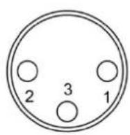
3 Pin XLR
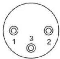

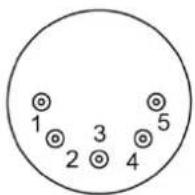
5 Pin XLR
| Pin | Function |
| 1 | Ground |
| 2 | Data- |
| 3 | Data+ |
| 4 | N/A |
| 5 | N/A |
DMX Operation
Making the DMX Connection – Connect the machine to a DMX controller or to one of the machines in the DMX chain. The machine uses a 3-pin or 5-pin XLR connector for DMX connection, the connector is located on the front of the machine.
Address Setup – Use control menu to set DMX address. The machine occupies 3 control channels. The starting address is defined as the first channel from which the machine will respond to the controller. Always double check to make sure there are no overlapping
channles in order to control the machine correctly.
DMX Channel Function
| Channel | Value | Function |
| 1 | 0-127 | Faze Mode |
| 128-255 | Fog Mode | |
| 2 | 0-5 | Output Off |
| 6-255 | Output 21-100% | |
| 3 | 0-5 | Fan speed at 20% |
| 6-255 | Fan speed 21-100% |
Status of W-DMX connection
| Symbol on the Liquid Crystal Display | Status of W-DMX connection |
| ● | Transmitter assigned, DMX signal received |
| ◎ | Transmitter assigned, No DMX signal |
| ⊙ | Transmitter link lost or linking to transmitter |
| ○ | Transmitter not assigned |
Service and Maintenance
- Do not allow the machine and fluid to become contaminated.
- Regularly fill distilled water to fluid tank and run the machine to clean the system. After cleaning, refill Antari fog fluids into fluid tank and make sure the machine can produce fog properly.
- It is recommended to run the machine on a monthly basis in order to achieve best performance and output condition.
- Excessive dust, liquid and dirt built up will degrade performance and cause overheating.
Technical Specifications
| - Input voltage | US model : AC 100-120V, 50 / 60Hz 13.5A |
| EU model : AC 220-240V, 50 / 60Hz 7A | |
| - Rated power | 1600W |
| - Warm-up time | 8 minutes (approx.) |
| - Fluid consumption | Fog Mode : 140ml/min |
| Faze Mode : 28ml/min | |
| - Fluid tank capacity | 5 Liters (1.32 gallon) |
| - Compatible fluid | Antari FLG-5E Heavy Fog Fluid |
| - Operating time | Faze Mode : 2.8 hrs at max. output |
| - Ambient temp. range | 0 °C - 40 °C (32 °F-104 °F) |
| - Control | Manual, Timer, DMX 512 |
| Wireless DMX | |
| - DMX channels | 3 channels |
| - Connection | Neutrik Powercon (Power) |
| XLR 3-pin and 5-pin (DMX) | |
| - Dimension | L728 W428 H719 mm |
| (L28.66 W16.85 H28.31 inch) | |
| - Weight | 52.5 kg (115.74 lbs) |

For current product information visit Antari at:www.antari.com For information requests please contact us at:sales@antari.com

MOBILEWEB/EN

MOBILEWEB/TC
G5 Short guide
Pinout
| Pin number | Funcon | Comment |
| J1:1 | GND | |
| J1:2 | Data - / RxD | RxD if J3:12 is connected to 3.3V, internal pulldown |
| J1:3 | Data + / TxD | RxD if J3:12 is connected to 3.3V, internal pulldown |
| J1:4 | Funcon switch | Pull up to 3.3V internally |
| J1:5 | OEM LED | 3.3V when On |
| J1:6 | 5V, 5-15V, 5-26V | Depending on card model |
| J1:7 | GND | |
| J1:8 | 3.3V | Dierent compared to G4 |
| J1:9 | Recepon Indicator / Mode | Dierent compared to G4 |
| J1:10 | Direcon | For TRX cards |
J3 is only for cads with -SPI extension
| J3:1 | Reset | |
| J3:2 | RX_NOT_TX | Output, High as RX, low as TX |
| J3:3 | Reserved | N/C internal use |
| J3:4 | Reserved | N/C internal use |
| J3:5 | Slave IRQ | IRQ signal when radiocard is SPI slave, not implemented |
| J3:6 | Overlay CS | CS Signal for overlay, acve high |
| J3:7 | SLAVE CS | CS Signal when radiocard is SPI slave, not implemented |
| J3:8 | SCK | Serial Clock signal |
| J3:9 | MISO | Master In, Slave out signal |
| J3:10 | MOSI | Master Out, Slave in signal |
| J3:11 | RS485 DIR | Direcon for RS485 driver |
| J3:12 | RS485 DISABLE | Connect to 3.3V when internal RS485 driver should be turned o |
Information for migrating from G4 to G5
PLEASE NOTE:
- Pin 6 can handle 5 to 15V input on all receiver cards A40895G5 and A40896G5SPI
- Pin 6 can handle 5V input on following transceiver cards A40890G5 and A40891G5SPI
- Pin 6 can handle 5 to 26V input on following transceiver cards A40890G5SPI
• Pin 8 can only be connected to 3.3V - Connect only one power source to the card
- OEM LED output 3.3V when the LED should be on, adjust resistor to give enough current to the LED, maximum output current is 0.5mA
- Pin 9 does not indicate MODE on the receiver, on receiver it is indicang recepon
- Shutdown voltage:
To ensure stable operaon, the voltage need to be according to the pinout list. But the card may be operaonal all the way down towards 1.5V, to ensure that the cards is disabled, power need to be reduced to 0V
Transceiver cards
IMPORTANT DMX direction for cards
All transceiver cards can operate as transmier or receiver, by seng the voltage on pin 10 in the following 3 conguraons
| Pin 10 voltage | Funcon |
| GND | Transmier (like G4 type O cards) |
| 3.3V (Open) | Receiver (like G4 type O cards) |
| 1.65V | Transmier or receiver (like G4 type R cards)Direcon is fetched from non-volale storage; direcon is changed if the buon (pin 4) is connected to GND during power upTo accomplish this, it is easiest to use two 4.7kOhm resistors, put one 4.7kOhm from pin 8 (3.3V) to pin 10 and one 4.7kOhm resistor from pin 7(GND) to pin 10. |
OEM LED indication
Transmitter card

On 900ms / O 100ms = no DMX present

Connuously On = DMX present

On 100ms / O 100ms = linking receivers

On 500ms / O 500ms = unlinking all receivers
Receiver card
Connuously O = not assigned to a transmier

On 900ms / O 100ms = assigned to a transmier, but no DMX present

Connuously On = assigned to a transmier and DMX present

On 100ms / O 100ms = link to transmier lost or linking to transmier
MODE LED indication
Transmitter card
Connuously On = G4S mode
Connuously O = G3 mode
Receiver card
Aer a low pass Iter ^1
The signal has a 1s period, that goes low in 100ms steps to indicate reception rate:
100% recepon: High
90% recepon: 900ms high, 100ms low
60% recepon 600ms high, 400ms low
1) The low pass Iter should Iter pulses that are up to 50 us long. Pin 9 can drive up to 0.5mA and for Iter purpose, there is a 330ohm resistor on the PCB between the driver and the pin.
There will be a pulse for each received radio package, if the pulse is high or low depends on the current signal level, there will be an error of up to 2 pulses for each second, so the error is negligible if the reception is measured with pulse counting.
LED Overlay Interface, G5 cards
For the G5 cards with SPI funconality (two pinheaders).
It is possible to implement a display interface similar to the one used on the W-DMX
BlackBox/WhiteBox range.
The overlay interface consists of an SPI interface that shis out data for the LEDs as described below.
To avoid icker a latched shi register is recommended.
The SPI speed is 2.5MHz and Overlay CS is pulled high before the output start and pulled low aer the SPI output has ended, SCK and MOSI is output signals.
LED order
| Name | Bit | Text | Color | Descripon |
| Power | 0 | PWR | Blue | Power, blinking in control mode |
| RDM | 1 | RDM | Green | RDM on/o |
| Green of Mode LED | 2 | Mode | Green | Mode indicator, part of a RGB LED |
| Red of Mode LED | 3 | Mode | Red | Mode indicator, part of a RGB LED |
| Blue of Mode LED | 4 | Mode | Blue | Mode indicator, part of a RGB LED |
| 2 Universe | 5 | UNIV | Green | Is receiving a 2 universe link |
| Link | 6 | LINK | Green | Link established |
| Data | 7 | DATA | Green | DMX Data present |
| Transmit Mode | 8 | TX | Green | Radio Transmier |
| Receive Mode | 9 | RX | Green | Radio Receiver |
| Reserved | 10 | |||
| Signal 1 | 11 | Red | Signal Strength | |
| Signal 2 | 12 | Yellow | Signal Strength | |
| Signal 3 | 13 | Green | Signal Strength | |
| Signal 4 | 14 | Green | Signal Strength | |
| Signal 5 | 15 | Green | Signal Strength | |