1068/021 - Detector GROTHE - Free user manual and instructions
Find the device manual for free 1068/021 GROTHE in PDF.
| Product type | Control keypad with LCD display for 1068 series security system |
| Brand | GROTHE |
| Model | 1068/021 |
| Dimensions (W x H x D) | 141 x 117 x 29 mm |
| Weight | Approx. 200 g |
| Power supply | Via control panel bus, 13.8 Vdc nominal (9-15 Vdc) |
| Standby current consumption | 17 mA (mains LED only) |
| Maximum current consumption | 93 mA (max backlight + all LEDs) |
| Display | Backlit graphic LCD, contrast and brightness adjustment |
| LED indicators | 3 LEDs: power, warning, zone status |
| Keys | 18 alphanumeric keys protected by flap |
| Buzzer | Adjustable sound |
| Programmable input | 1 input (IN1) for detector, configurable NC, NO, single or double balanced |
| Enclosure protection | IP40 / IK06 |
| Operating temperature | From 0 °C to 50 °C (estimate) |
| Mounting | Wall, indoor, recommended height 160 cm (or 75-140 cm for PRM) |
| Bus connection | Daisy chain or star, max length 400 m, shielded 4-conductor cable |
| Main functions | System control and programming, keypad enrollment, alarm, double balanced EN50131 |
| Maintenance and cleaning | Clean with a soft, dry cloth. Do not use abrasive products. |
| Security | Tamper anti-removal, anti-extraction protection (tamper jumper included) |
| Spare parts and repairability | Fixing screw supplied; wall plugs and 2.7 kΩ resistors supplied; no specific spare parts listed |
| General information | Indoor use only. Compliant with EN50131 (double balanced). WEEE: recycle at collection point. |
Frequently Asked Questions - 1068/021 GROTHE
User questions about 1068/021 GROTHE
0 question about this device. Answer the ones you know or ask your own.
Ask a new question about this device
Download the instructions for your Detector in PDF format for free! Find your manual 1068/021 - GROTHE and take your electronic device back in hand. On this page are published all the documents necessary for the use of your device. 1068/021 by GROTHE.
USER MANUAL 1068/021 GROTHE
natural_image
White urmet appliance with digital display and control buttons (no visible text or symbols on body)Through the following QR Code, it is possible to download the eventual new version of the booklet in English, French and German language.

http://qrcode.urmet.com/default.aspx?prodUrmet=141753&lingua=en
ENGLISH
GENERAL DESCRIPTION
The 1068/021 indoor display keypad, used to control and program the 1068 series system is equipped with :
- LCD backlit display with contrast and luminosity regulation;
• 3 LED to signal the system status (Power supply, Recommendations, Zone status);
• 18 door-protected alphanumerical keys; - buzzer with adjustable volume;
- 1 programmable input.
A tamper jumper is supplied with the product to bypass the keypad opening/removal button. Use of this feature will cancel EN50131 certification.
The keypad is powered by the bus that connects it to the control panel.
WARNING! In this document there are only present some essential indications about product. For further and more detailed information, refer to manuals concerning 1068 series control panels.
POSITIONING
Keypad must be positioned:
- in an environment that is sheltered and protected from water and humidity;
• on a dry and level wall; - in the vicinity of the accesses to area to be protected;
- in an inner location which is not subjected to excessive sudden rises/falls in temperature, and is protected by anti-burglar system; at 160 cm height for normal installations. For disabled or special needs users of the D1 type (elderly) and D2 type (lower limb motor
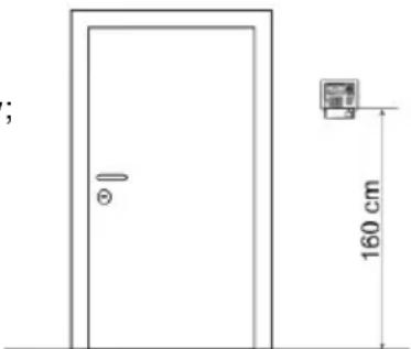
natural_image
Simple line drawing of a door with a small inset image showing a wall-mounted device, dimensioned 160 cm (no text or symbols)difficulties), the centre of the device must be arranged at a height comprised between 75 cm and 140 cm with respect to the floor. For more details, see technical standard CEI 64-21:2016-12 – Residential environments. Systems suited for use by people with disabilities or special needs.
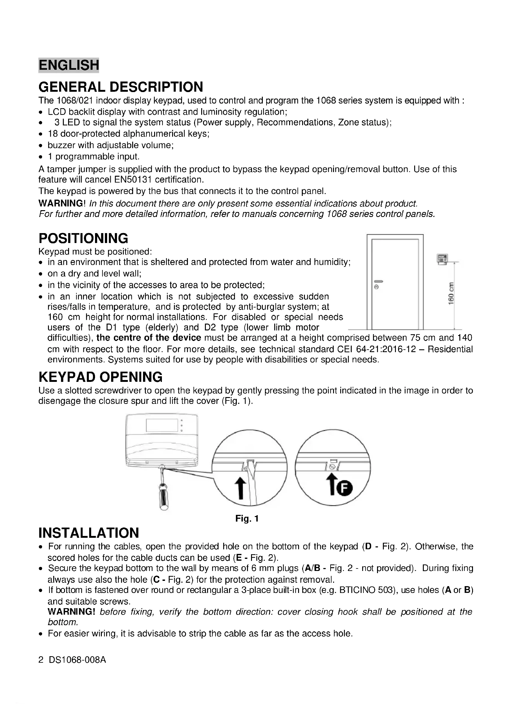
KEYPAD OPENING
Use a slotted screwdriver to open the keypad by gently pressing the point indicated in the image in order to disengage the closure spur and lift the cover (Fig. 1).
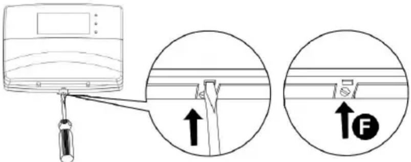
Fig. 1
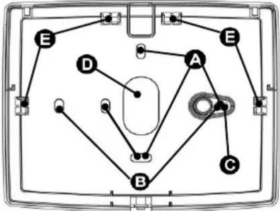
INSTALLATION
- For running the cables, open the provided hole on the bottom of the keypad (D - Fig. 2). Otherwise, the scored holes for the cable ducts can be used (E - Fig. 2).
- Secure the keypad bottom to the wall by means of 6 mm plugs (A/B - Fig. 2 - not provided). During fixing always use also the hole (C - Fig. 2) for the protection against removal.
- If bottom is fastened over round or rectangular a 3-place built-in box (e.g. BTICINO 503), use holes (A or B) and suitable screws.
WARNING! before fixing, verify the bottom direction: cover closing hook shall be positioned at the bottom. - For easier wiring, it is advisable to strip the cable as far as the access hole.
- Close the keypad by screwing the screw provided in the hole. (F - Fig. 1).
flowchart
graph TD
    A --> B
    A --> C
    A --> D
    A --> E
    B --> C
    B --> D
    B --> E
    C --> D
    C --> E
    D --> E
    E --> A
Fig. 2
BUS CONNECTION
Keypad can be connected on bus either in a cascade or star. Keypad position along bus is not important. The overall length of all bus sections must not exceed 400 metres.
For wiring, use 4 lead screened cable for anti-intrusion (2 leads for power supply and 2 leads for data connection). Lead section must be chosen taking into account voltage drop caused by connection length. In counting out overall system absorption, also consider max consumption in keypad (95 mA).
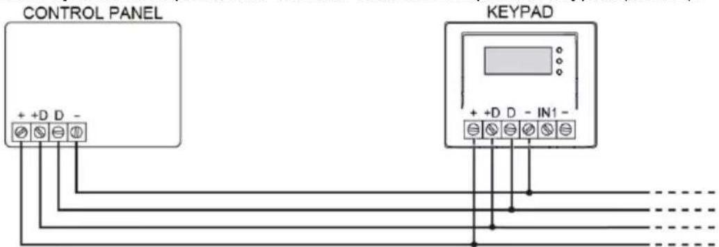
POWER SUPPLY AND DATA BUS
KEYPAD CAPTURE
To acquire the keypad the first time it is switched on, press the key associated with the F1 symbol that appears on the display.
Proceed as follows to restore default settings (Reset) on the keypad, if necessary:
- Disconnect power from the keypad
- Open the keypad tamper protection
- Restore power supply to the keypad
- Press the key associated with the F1 symbol within 10 seconds (Fig.3). Another screen will appear (Fig.4).
- Press the key associated with the F1 symbol to confirm parameter reset. Press the key associated with F3 “Cancel” symbol to return to the previous screen
For further information about capture procedure, refer to manual concerning control unit installation.
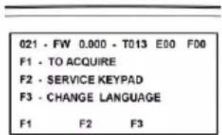
Fig. 3
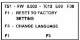
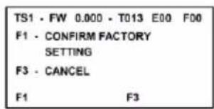
Fig. 4
ALARM INPUT
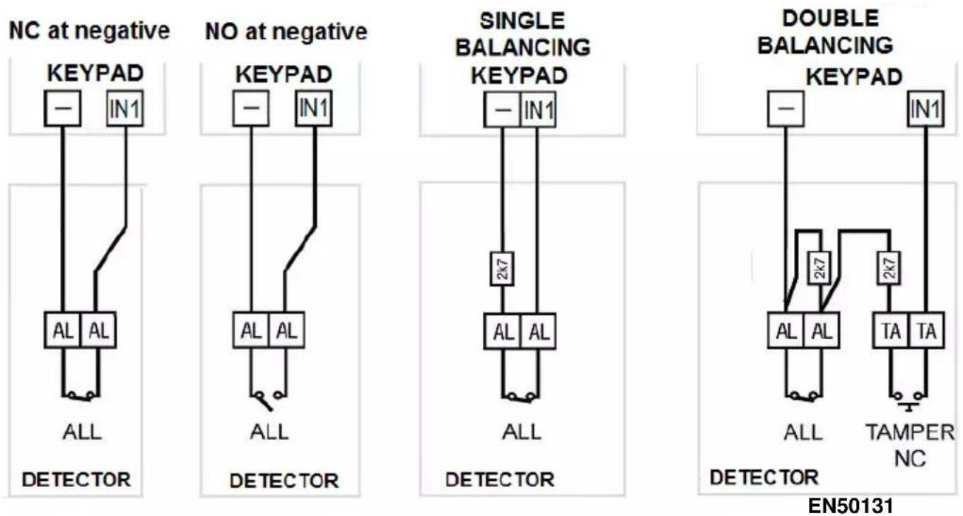
Possibly connect a sensor to the auxiliary input IN1. The input is referred to ground (-) and can be programmed as NC, NO, Single balancing and Double balancing. The input can also manage fast signals coming from seismic sensors or rolling shutters; in this case, the connecting mode is fixed on NC. In order to connect with balancing use the provided 2.7kohm resistors with 1% tolerance.
WARNING! "Double balance" is the only EN50131 compliant connection mode. Refer to the manuals of 1068 series control units for further, more detailed information.
TECHNICAL CHARACTERISTICS
Nominal supply voltage (taken from the control unit via a communication bus) 13.8 Vdc
Min/max operation voltage....9 Vdc ÷ 15 Vdc
Nominal current absorbed at 13.8 Vdc:
In stand-by, only LED for presence mains supply 17 mA
Operative, with backlighting at minimum value 22 mA
Operative, with backlighting at maximum value and all LEDs ON 93 mA
Programmable input .... 1
Degree of protection of casing....IP40 / IK06
Dimensions (L x H x D) in mm 141 x 117 x 29
DESCRIPTION GÉNÉRALE
natural_image
Simple line drawing of a door with a small inset image showing a wall-mounted device, dimensioned 160 cm (no text or symbols)Fig. 1
INSTALLATION
Abb.1
INSTALLATION
DIRECTIVE 2012/19/EU OF THE EUROPEAN PARLIAMENT AND OF THE COUNCIL of 4 July 2012 on waste electrical and electronic equipment (WEEE)
The symbol of the crossed-out wheeled bin on the product or on its packaging indicates that this product must not be disposed of with your other household waste.
Instead, it is your responsibility to dispose of your waste equipment by handing it over to a
designated collection point for the recycling of waste electrical and electronic equipment.
The separate collection and recycling of your waste equipment at the time of disposal will help to conserve natural resources and ensure that it is recycled in a manner that protects human health and the environment.
For more information about where you can drop off your waste equipment for recycling, please contact your local city office, your household waste disposal service or the shop where you purchased the product.
FRANÇAIS