
EZM-3735 - Digital timer switch Emko - Free user manual and instructions
Find the device manual for free EZM-3735 Emko in PDF.
| Product Type | Digital Timer – Time Switch |
| Housing Dimensions | 76 x 34.5 x 71 mm |
| Panel Cutout | 71 x 29 mm |
| Weight | 0.20 kg |
| Power Supply | 24 V~, 115 V~, 230 V~ (50/60 Hz) or 10-30 V===, 1.5 VA |
| Time Accuracy | ±1 % |
| Display | 4-digit red LED (height 14 mm) |
| Relay Output | 16(8) A @ 250 V~, 1 NO+NC contact |
| Digital Inputs | Start and Pause (mechanical contact) |
| Internal Buzzer | ≥83 dB, adjustable from 0 to 16 sounds |
| Protection Rating | IP65 (front), IP20 (rear) |
| Operating Temperature | -30 °C to +80 °C |
| Max Relative Humidity | 90 % non-condensing |
| Max Altitude | 2000 m |
| Mounting | Flush panel mounting (max panel thickness 15 mm) |
| Timer Modes | Count up or count down, programmable setpoint |
| Additional Functions | Pause, external start/stop, password protection, input filtering |
| Recommended Cleaning | Cloth dampened with ethyl alcohol or water |
| Warranty | 2 years |
| Approvals | CE, UKCA |
Frequently Asked Questions - EZM-3735 Emko
User questions about EZM-3735 Emko
0 question about this device. Answer the ones you know or ask your own.
Ask a new question about this device
Download the instructions for your Digital timer switch in PDF format for free! Find your manual EZM-3735 - Emko and take your electronic device back in hand. On this page are published all the documents necessary for the use of your device. EZM-3735 by Emko.
USER MANUAL EZM-3735 Emko
text_image
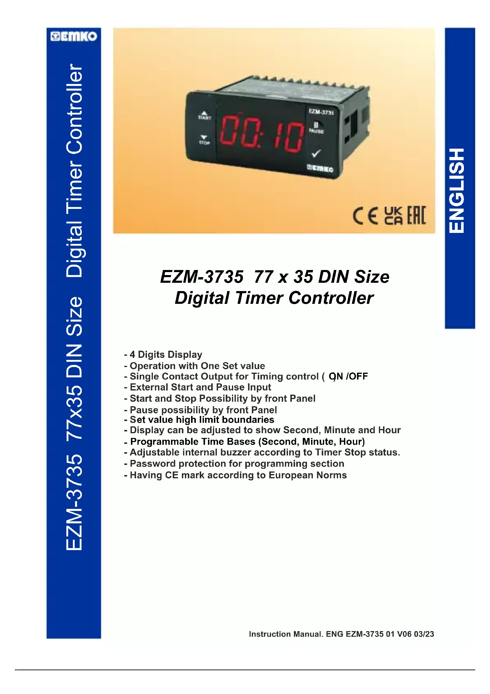
E2M-3735 START 00:10 STOP FAULT EAUSE ✓ CE UK ECEZM-3735 77 x 35 DIN Size Digital Timer Controller
- 4 Digits Display
- Operation with One Set value
- Single Contact Output for Timing control ( QN /OFF
- External Start and Pause Input
- Start and Stop Possibility by front Panel
- Pause possibility by front Panel
- Set value high limit boundaries
- Display can be adjusted to show Second, Minute and Hour
- Programmable Time Bases (Second, Minute, Hour)
- Adjustable internal buzzer according to Timer Stop status.
- Password protection for programming section
- Having CE mark according to European Norms
1. Preface
EZM-3735 Programmable Timer can be used in package machines, production and quality control rollers, and can be adapted easily to all mechanical construction and automation system. Some application fields which they are used are below:
Application Fields
Package machines,
Quality Control rollers,
Filling Systems,
Tool Benches,
Building Automation.
Production bands
1.1 Environmental Ratings


Operating Temperature : -30^ to +80^
Max. Operating Humidity : 90% Rh (non-condensing)
Altitude : Up to 2000 m.
Forbidden Conditions:
Corrosive atmosphere
Explosive atmosphere
Home applications (The unit is only for industrial applications)
1.2 General Specifications
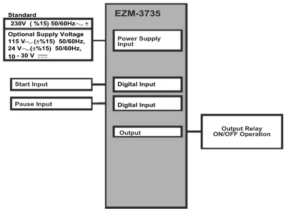
flowchart
graph TD
    A["Standard\n230V (%15) 50/60Hz~ ±"] --> B["EZM-3735"]
    C["Optional Supply Voltage\n115 V~(±%15) 50/60Hz,\n24 V~(±%15) 50/60Hz,\n10 - 30 V ==="] --> B
    D["Start Input"] --> B
    E["Pause Input"] --> B
    B --> F["Power Supply Input"]
    B --> G["Digital Input"]
    B --> H["Digital Input"]
    B --> I["Output"]
    J["Output Relay ON/OFF Operation"] --> B
1.3 Installation
A visual inspection of this product for possible damage occurred during shipment is recommended before installation. It is your responsibility to ensure that qualified mechanical and electrical technicians install this product.
If there is danger of serious accident resulting from a failure or defect in this unit, power off the system and separate the electrical connection of the device from the system.
The unit is normally supplied without a power supply switch or a fuse. Use power switch and fuse as required.
Be sure to use the rated power supply voltage to protect the unit against damage and to prevent failure.
Keep the power off until all of the wiring is completed so that electric shock and trouble with the unit can be prevented.
Never attempt to disassemble, modify or repair this unit. Tampering with the unit may results in malfunction, electric shock or fire.
Do not use the unit in combustible or explosive gaseous atmospheres.
During putting equipment in hole on the metal panel while mechanical installation some metal burrs can cause injury on hands, you must be careful.
Montage of the product on a system must be done with it's fixing clamps. Do not do the montage of the device with inappropriate fixing clamp. Be sure that device will not fall while doing the montage.
It is your responsibility if this equipment is used in a manner not specified in this instruction manual.
1.4 Warranty
EMKO Elektronik warrants that the equipment delivered is free from defects in material and workmanship. This warranty is provided for a period of two years. The warranty period starts from the delivery date. This warranty is in force if duty and responsibilities which are determined in warranty document and instruction manual performs by the customer completely.
1.5 Maintenance
Repairs should only be performed by trained and specialized personnel. Cut power to the device before accessing internal parts.
Do not clean the case with hydrocarbon-based solvents (Petrol, Trichlorethylene etc.). Use of these solvents can reduce the mechanical reliability of the device. Use a cloth dampened in ethyl alcohol or water to clean the external plastic case.
1.6 Manufacturer Company
Manufacturer Information:
Emko Elektronik Sanayi ve Ticaret A.Ş.
Repair and maintenance service information:
Emko Elektronik Sanayi ve Ticaret A.Ş.
2. General Description

text_image
E2M-3735 E2M-3735 SP h m s II START 8.8:8.8 PAAUSE ✓ STOP EEMKO Front Panel IP65 protection NEMA 4X Mounting Clamp Panel Surface (maximum thickness 15 mm / 0.59 inch)2.1 Front View and Dimensions of EZM-3735 Digital Timer
text_image
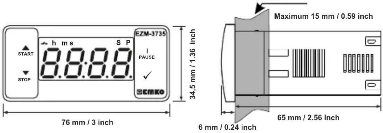
START h ms S P 8.8:8.8 E2M-3735 I PAUSE STOP ECMKo 76 mm / 3 inch 34,5 mm / 1.36 inch Maximum 15 mm / 0.59 inch 6 mm / 0.24 inch 65 mm / 2.56 inch2.2 Panel Cut-Out
other
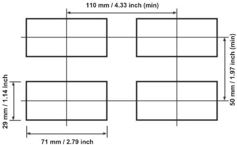
| Dimension | Value | | ----------------- | ------------ | | Top Left | 110 mm / 4.33 inch (min) | | Middle Right | 50 mm / 1.97 inch (min) | | Bottom Right | 29 mm / 1.14 inch | | Bottom Left | 71 mm / 2.79 inch |2.3 Panel Mounting
text_image
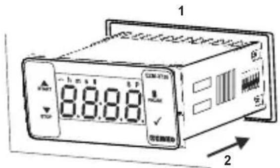
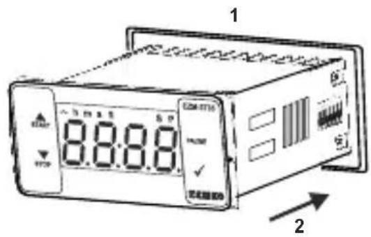
1 8:8:8.0 OFF 21-Before mounting the device in your panel, make sure that the cut-out is of the right size.
2-Insert the device through the cut-out. If the mounting clamps are on the unit, put out them before inserting the unit to the panel.
text_image
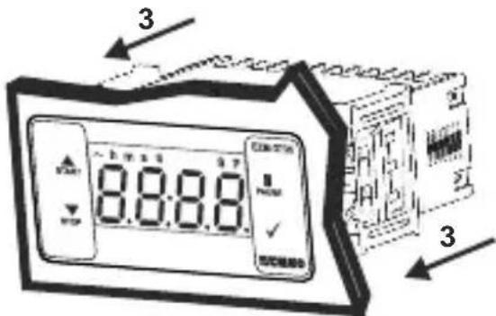
3 8:8:8 33- Insert the mounting clamps to the fixing sockets that located left and right sides of device and make the unit completely immobile within the panel
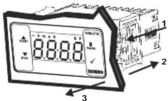
2.4 Removing from the Panel
text_image
8:8:8 1 2 31-Pull mounting clamps from left and right fixing sockets.
2-Pull the unit through the front side of the panel

Before starting to remove the unit from panel, power off the unit and the related system.
4. Electrical Wiring Diagram
text_image
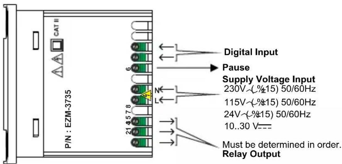
CAT II P/N : EZM-3735 6 Digital Input Pause Supply Voltage Input 230V~(%±15) 50/60Hz 115V~(%±15) 50/60Hz 24V~(%±15) 50/60Hz 10..30 V--- Must be determined in order. Relay OutputNote-1 : For 230V\~, 115V\~ or 24V\~ power supply; input4 is "L", input 5 is "N", for 10...30V==power supply; input 4 is "-", input 5 is "+".
4.1 Supply Voltage Input Connection of the Device
Power Supply Connection
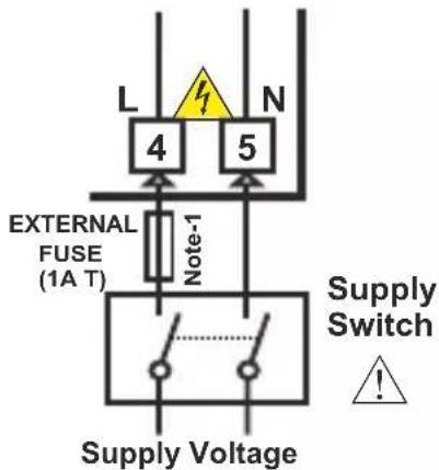
text_image
L 4 N 5 EXTERNAL FUSE (1A T) Note-1 Supply Switch ! Supply Voltage230V\~( %15) 50/60Hz ,
115V ( 12 45) 50/60Hz,
24V\~( %15) 50/60Hz ,
10...30 V-4.5 W
Must be determined in order.

Make sure that the power supply voltage is the same indicated on the instrument.
Switch on the power supply only after that all the electrical connections have been completed.
Supply voltage range must be determined in order. While installing the unit, supply voltage range must be controlled and appropriate supply voltage must be applied to the unit.

There is no power supply switch on the device. So a power supply switch must be added to the supply voltage input.
Power switch must be two poled for separating phase and neutral, On/Off condition of power supply switch is very important in electrical connection.
External fuse that on power supply inputs must be on phase connection.
External fuse that on — power supply inputs must be on (+) connection.
Note-1 : External fuse is recommended.
Note-2 : For 230V\~, 115V\~ or 24V\~ power supply; input 4 is "L", input 5 is "N", for 10...30V---power supply; input 4 is "-", input 5 is "+".
4.2 Device Label and Connection Diagram
230V\~ CONNECTION DIAGRAM
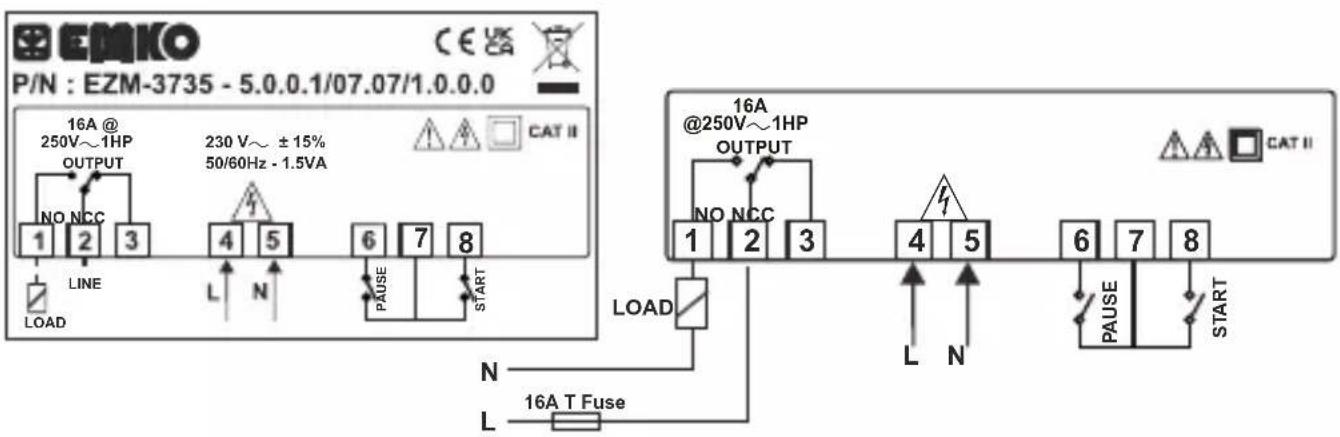
text_image
P/N : EZM-3735 - 5.0.0.1/07.07/1.0.0.0 16A @ 250V~1HP OUTPUT 230 V~ ± 15% 50/60Hz - 1.5VA NO NCC 1 2 3 LINE LOAD L N 4 5 6 7 8 PAUSE START LOAD N L 16A T Fuse 16A @250V~1HP OUTPUT NO NCC 1 2 3 4 5 6 7 8 L N PAUSE START CAT II5.Front Panel Definition and Accessing to the Menus
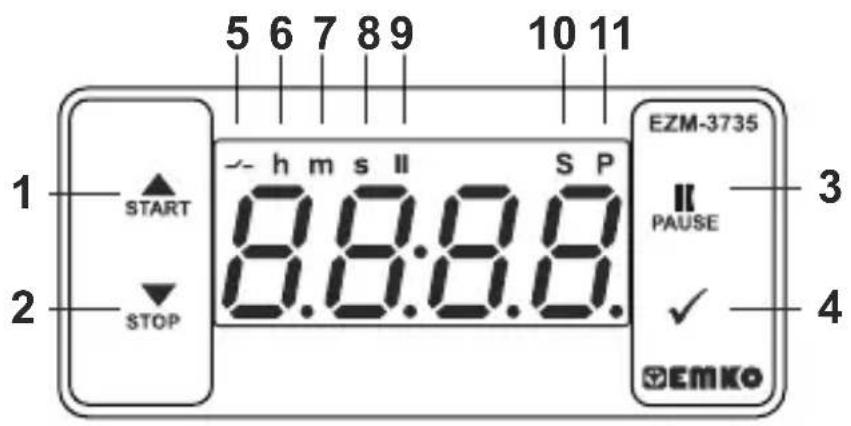
text_image
1 START 2 STOP 5 6 7 8 9 h m s II S P 8:3:37.8.8. EZM-3735 II PAUSE ✓ EMKO 3 4BUTTON DEFINITIONS
1. Increment Button and Start Button :
** It is used to increase the value in the Set screen and Programming mode.
** It is used for Start the Timer in the Main Screen.
2. Decrement, Silencing Buzzer and Stop Button :
** It is used to decrease the value in the Set screen and Programming mode.
** It is used to silence the buzzer.
** It is used for Stop the Timer in the Main Screen.
3. Pause Button :
** While digital timer is running if Pause button is pressed or external pause input is activated, timer stops running. After that if the pause button is pressed again or external pause input is deactivated, timer starts running again.
4. Enter Button:
** In the main operation screen; if this button pressed, set value will be displayed. Value can be changed using increment and decrement buttons. When Set button pressed again, value is saved and returns back to main operating screen.
** To access the programming screen; in the main operation screen, press this button for 5 seconds.
** It is used to saving value in the Set screen and programming screen.
LED DEFINITIONS
5. Output led :
** This led indicates that Output is active.
6. Hour led :
** Indicates that device is in Hour mode.
7. Minute led :
** Indicates that device is in Minute mode.
8.Second led :
** Indicates that device is in Second mode.
9.Pause led :
** This led indicates that Pause is active.
10.Set led :
** Indicates that device is in Set value changing mode.
11. Program led :
**Blinks in programming mode.
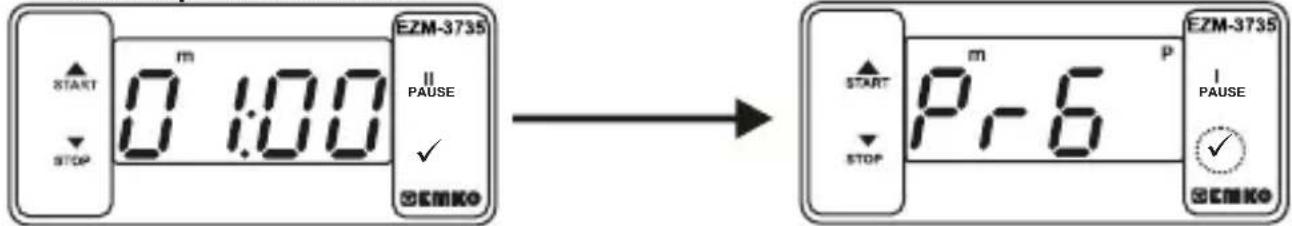
6. Changing and Saving Timing Set Value
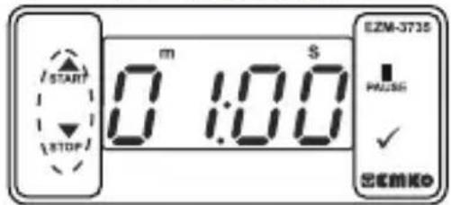
Main Operation Screen
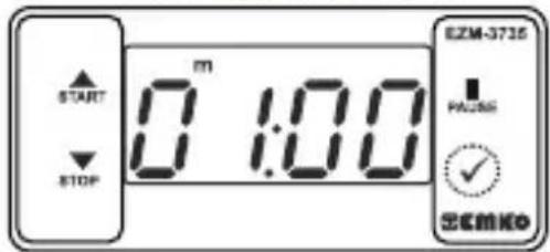
text_image
START STOP m 0 1:00 EZM-3735 PACS ✓ ECMKOWhen Enter button pressed "S" led will be active and temperature set value will be displayed.

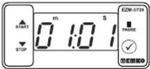
SET Value Screen
text_image
START STOP m 1:00 EZM-3735 PASS ✓ OKENKOTimer set value can be changed with increment and decrement buttons.
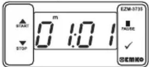
text_image
START STOP m 1:0 S EZM-3735 PAUSE ✓ SEMKOWhen Enter button pressed Timing set value can be saved.

Main Operation Screen
text_image
START STOP m 0:10 EZM-3735 FAUSE ✓ ©EMK©“S” will be inactive and goes back to main operation screen.
Timer set value parameter (Default=01:00)
Timer set value, can be programmed between minimum Timer set value 00:01 and [JPI] maximum set limit.
6.1 Programming Mode Parameter List

Filter Time of Digital Inputs (Default = 100)
It is used for protection against the electrical contact debounce or the signal that is less than the determined pulse time.
It can be adjusted from 2 to 250 msec.

Time Unit and Scale Selection (Default = 1) Parameter

Hour / Minute It can be adjusted from 000 to 9959.

Minute /Second It can be adjusted from 00.0 to 99.59.

Second /10 Milisecond It can be adjusted from 00:0 to 9999.

Start Type Selection Parameter (Default = EYPO)

Start / Stop buttons can be used to run or stop the timer.
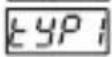
Start / Stop buttons can be used to run or stop the timer.

External Start Input can be used to run or stop the timer.

External Start Input can only be used to run the timer. In order to stop the timer the Stop button must be used.
For detailed information refer to graphics.

Output Functions (Default = OFF)

if ON is selected timer runs by start and relay contact is closed. When time is over, relay contact opens.

if OFF is selected timer runs by start. When time is over, relay contact is closed.

Buzzer Function Selection Parameter (Default = 0)
if this parameter is selected 0, Buzzer is inactive. Adjustable 16 different buzzer sounds. It can be adjusted from 0 to 16.

Buzzer is active during this time (Default = \_\_\_\_ )
Buzzer stays active during this time. It can be adjusted from 1 to 99 seconds When this parameter is 1, if decrement button is pressed, - - - - is observed. In this condition buzzer is active till buzzer Stop button is pressed.

Data Record (Default = 1)
Timer count value is saved to memory when power is disconnected and restored on power up.
Timer count value is not saved to memory when power is disconnected. When power up, Set value is shown on the screen.

Output Relay On Delay Time (Default = 0)
It determines how long output relay will be active. If it is 0000 second, then it operates indefinitely. It can be adjusted from 0000 to 5955 minute/second. This parameter is active only if outF = off.

Maximum Set Value Parameter (Default = 01:00)
Maximum set value for set time value. It can be adjusted from 000 to 9999. ( If time value is monitored in milliseconds, SEc
It can be adjusted from 0001 to 9959. (If time value is monitored in Hours hour or Minutes. 7 in)

Timer Counting Direction (Default = 1)

Timer upcount. 0 to Set value.

Timer Downcount. Set value to 0.

Button Protection Parameter 0( Default = )

Button protection is not active.
Bottom protection is active for Timer set value.

Programming Section Access Password( Default = 0 )
It is used for accessing to the programming section. It can be adjusted from 0 to 9999. If it is selected 0, password will not be asked
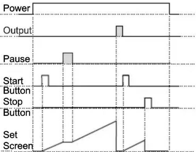
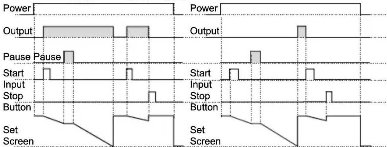
6.3 Operation Graphics of ESM-3735 Digital Timer
- Control diagram using Start / Stop buttons.
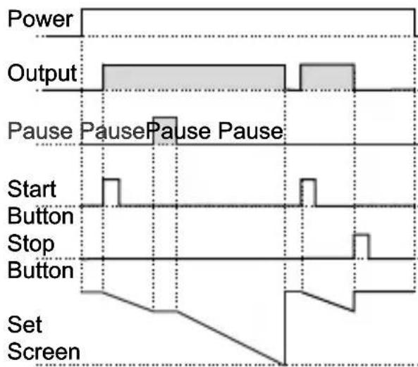
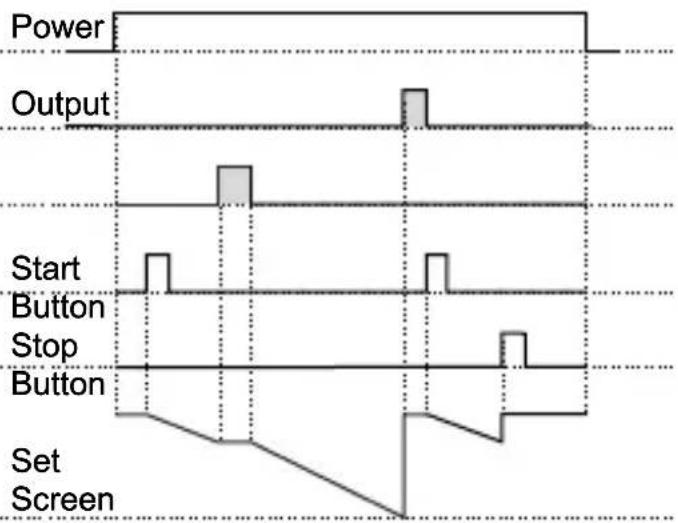
1.1 If Start type Strt is selected as typ0.
1.1.1 If downcount = 1 and is -n the control diagram is shown in Figure 1.1
1.1.2 If downcount = 1 and is the control diagram is shown in Figure 1.2
text_image
Power Output Pause Pause Pause Pause Start Button Stop Button Set ScreenFigure 1.1
text_image
Power Output Start Button Stop Button Set ScreenFigure 1.2
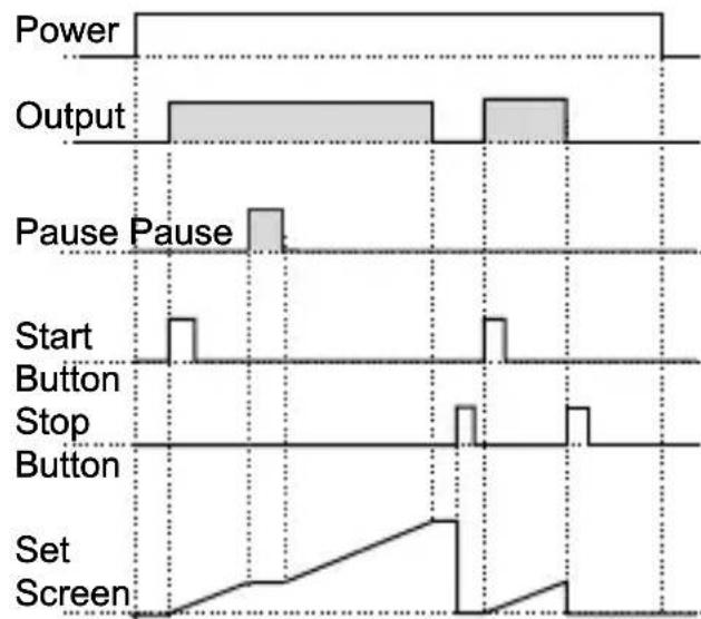
1.2 If Start type Strt is selected as TYPO.
1.2.1 If Upcount =0 and is -n the control diagram is shown in Figure 1.3
1.2.2 If Upcount = 0 and is the control diagram is shown in Figure 1.4
other
| Signal | Value | |-----------------|-------| | Power | 10000 | | Output | 10000 | | Pause | 1000 | | Start Button | 100 | | Stop Button | 100 | | Set Screen | 100 |Figure 1.3
other
| Signal | Value | |-----------------|-------| | Power | 0 | | Output | High | | Pause | High | | Start Button | Low | | Stop | Low | | Button | Low | | Set Screen | Linear |Figure 1.4
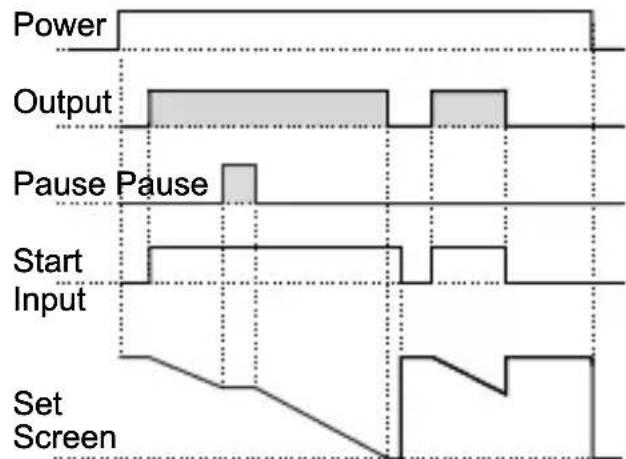
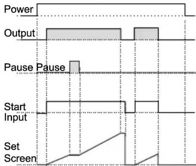
- Control diagram using Start / Stop buttons.
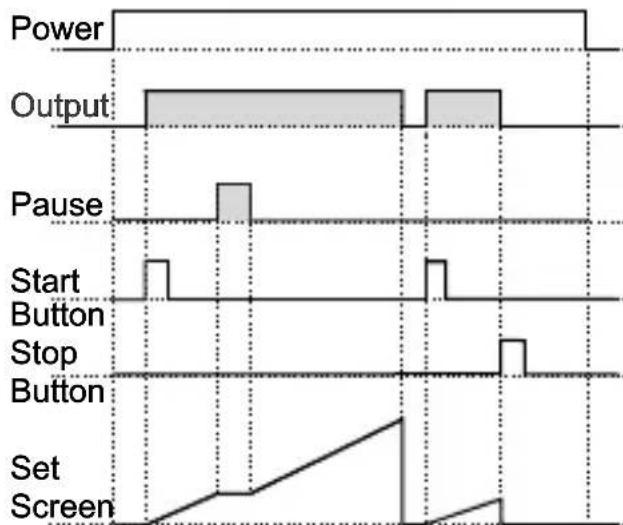
2.1 If Start type Strt is selected as typ 1.
2.1.1 If Downcount = 1 and is -n the control diagram is shown in Figure 2.1
2.2.2 If Downcount dE_ct=1 and outF is off the control diagram is shown in Figure 2.2
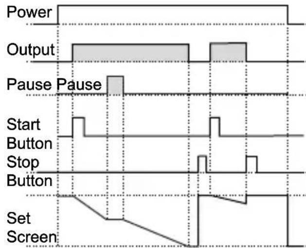
other
| Signal | Value | |-----------------|-------| | Power | 0 | | Output | High | | Pause Pause | High | | Start Button | Low | | Stop Button | Low | | Set Screen | Low |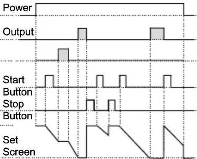
other
| Signal | Value | |-----------------|-------| | Power | High | | Output | High | | Start Button | Low | | Stop Button | Low | | Set Screen | Low |Figure 2.1 Figure 2.2
1.4 If Start type Strt is selected as typ.
1.4.1 If Upcount dE_ct = 0 and putF is p-n the control diagram is shown in Figure 2.3
1.4.2 If Upcount dE_ct = 0 and outF is pFF the control diagram is shown in Figure 2.4
other
| Signal | Value | |-----------------|-------| | Power | 1 | | Output | 1 | | Pause Pause | 1 | | Start Button | 1 | | Stop Button | 1 | | Set Screen | 1 |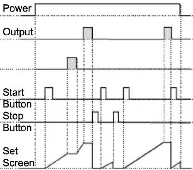
other
| Signal | Value | |-----------------|-------| | Power | High | | Output | Low | | Start Button | Low | | Stop Button | Low | | Set Screen | Low |Figure 2.3 Figure 2.4
- Control diagram using External Digital Start Input.
3.1 If Start type Start is selected as type.
3.1.1 If Downcount c = 1 and is - n the control diagram is shown in Figure 3.1
3.1.2 If Downcount = 1 and is the control diagram is shown in Figure 3.2
text_image
Power Output Pause Pause Start Input Set Screen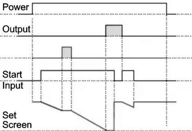
text_image
Power Output Start Input Set ScreenFigure 3.1 Figure 3.2
3.2.1 If Upcount = 0 and is -n the control diagram is shown in Figure 3.3
3.2.2 If Upcount =0 and is the control diagram is shown in Figure 3.4
text_image
Power Output Pause Pause Start Input Set Screen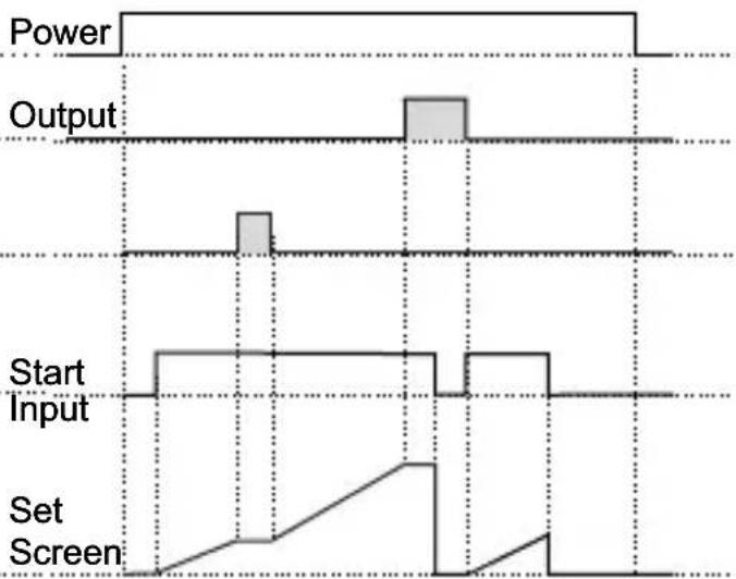
text_image
Power Output Start Input Set ScreenFigure 3.3 Figure 3.4
- Control diagram using External Digital Start Input.
4.1 If Start type Sert is selected as typ3.
4.1.1 If Downcount dE_ct=1 and outF is a-n the control diagram is shown in Figure 4.1
4.1.2 If Downcount = 1 and is the control diagram is shown in Figure 4.2
other
| Signal | Power | Output | Pause Pause | Start Input Stop | Button | Set Screen | |-----------------|-------|--------|-------------|------------------|--------|------------| | Power | High | Low | High | Low | Low | Low | | Output | High | Low | High | Low | Low | Low | | Pause Pause | Low | High | High | Low | Low | Low | | Start Input Stop| Low | Low | Low | Low | Low | Low | | Button | Low | Low | Low | Low | Low | Low | | Set Screen | Low | Low | Low | Low | Low | Low | | Set Screen | Low | Low | Low | Low | Low | Low |Figure 4.1 Figure 4.2
4.2.1 If Upcount = 0 and is -n the control diagram is shown in Figure 4.3
4.2.2 If Upcount =0 and is the control diagram is shown in Figure 4.4
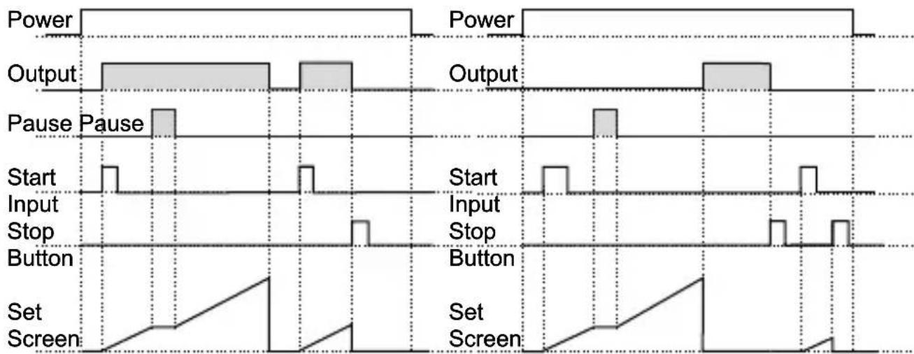
Figure 4.3 Figure 4.4
6.5 Entering To The Programming Mode, Changing and Saving Parameter
Main Operation Screen
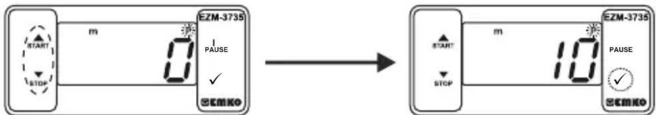
When Enter button is pressed for 5 seconds, "P" led starts to blink. If programming mode entering password is different from 0, programming mode entering screen will be observed.
Note1: If programming mode accessing password is 0, -5±F Temperature Unit screen is observed instead of programming screen
Programming Mode Entering Screen
Press Enter button for accessing to the password entering screen.
flowchart
graph LR
    A["Start"] --> B{m}
    B --> C["0"]
    C --> D["EZM-3735"]
    D --> E["10"]
    E --> F["STOP"]
    F --> G["✓"]
    G --> H["SEMko"]
Password Entering Screen
Enter programming mode accessing password with increment and decrement buttons.
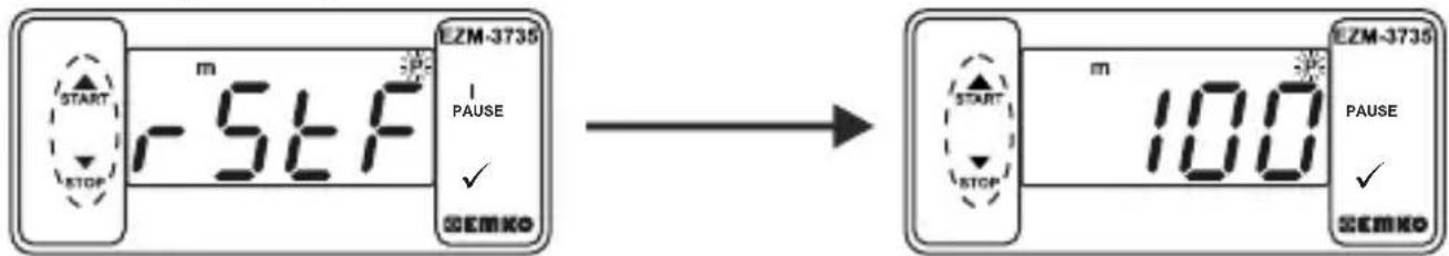
Password Entering Screen
Press OK button for entering the password.
Note2: If programming mode accessing password is 0, only three parameters are accessible, and the parameter values can be changed.
Programming Screen
text_image
E2M-3735 START STOP m -5LF I PAUSE ✓ SEMko → E2M-3735 START STOP m 100 E2M-3735 PAUSE ✓ SEMkoPress Enter button for accessing to the parameter value. Press increment button for accessing to the next parameter, press decrement button for accessing to the previous parameter.
Filter Time of Start Input
Change the value with increment and decrement buttons.
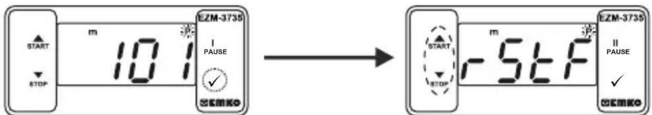
text_image
EZM-3735 10 I I PAUSE ✓ START STOP EEMKO EZM-3735 10 I I PAUSE ✓ START STOP EEMKOFilter Time of Start Input
Press OK button for saving the parameter.
Filter Time of Start Input
Press increment button for accessing to the next parameter, press decrement button for accessing to the previous parameter

If no operation is performed in programming mode for 20 seconds, device turns to main operation screen automatically..
7. Specifications
Device Type : Digital Timer
Housing&Mounting : 76mm x 34.5mm x 71mm plastic housing for panel Mounting. Panel cut-out is 71x29mm.
Protection Class : Ip65 at front, Ip20 at rear.
Weight : Approximately 0.20 Kg.
Environmental Ratings : Standard, indoor at an altitude of less than 2000 meters with none condensing humidity.
Storage / Operating Temperature : -40 °C to +80 C / -30 C to +80 C
Storage / Operating Humidity : 90 % max. (None condensing)
Installation : Fixed installation
Overvoltage Category : II.
Pollution Degree : II, office or workplace, none conductive pollution
Operating Conditions : Continuous
Supply Voltage and Power : 230V( %15) 50/60Hz - 1.5VA
: 115V (\~%±15) 50/60Hz - 1.5VA
: 24V\~(‰15) 50/60Hz - 1.5VA
Time Accuracy : within ±%1 error
Digital Start and Pause Inputs : Mechanical contact
Control Form : ON / OFF
Relay Output : 16(8) A@250 V ∼ for Resistive load (Output Relay)
(Electrical life : 100.000 switching at full load)
Display : 14 mm Red 4 digits LED Display
LED : S (Green), P (Green), h (Red), m(Red), s (Red), Output (Red)
Internal Buzzer : ≥83dB
All order information of EZM-3735 Digital Timer are given on the table at above. User may form appropriate device configuration from information and codes that at the table and convert it to the ordering codes. Firstly, supply voltage then other specifications must be determined. Please fill the order code blanks according to your needs.
Please contact us, if your needs are out of the standards.


Your Technology Partner
Thank you very much for your preference to use Emko Elektronik products, please visit our web page to download detailed user manual.
www.emkoelektronik.com.tr
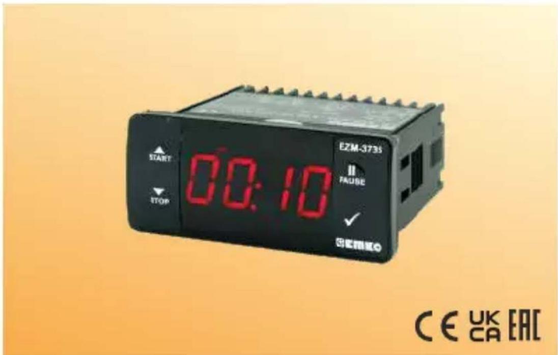
text_image
E2M-3735 START 00:10 FAUBE STOP CE UK CA EACother
| Section | Width (mm) | | ------- | ---------- | | Top Left | 110 | | Top Right | 50 | | Bottom Left | 29 | | Bottom Right | 71 |2.3 Tafeleinbau
text_image
1 8:8:8.8 E2M-0716 H250 ✓ 无阻断器 2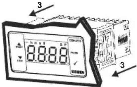
text_image
3 8:00:15 5 P TOM-2731 PUMS 2 2 2 2 2 2 2 2 2 2 2 2 2 2 2 2 2 2 2 2 2 2 2 2 2 2 2 2 2 2 2 2 2 2 2 2 2 2 2 2 2 2 2 2 2 2 2 2 2 2 3When Enter button pressed "S" led will be active and temperature set value will be displayed.
Sollwert-Bildschirm

text_image
START STOP m 0 1:00 S EZM-3735 PULSE ✓ EEMKOtext_image
E2M-3735 START 00:10 FAUSE STOP CE UK CA EACother
| Event Type | Start | Stop | End | | ---------------- | ----- | ---- | --- | | Alimentation | 0 | 0 | 0 | | Sortie | 1 | 0 | 1 | | Bouton Start | 0 | 0 | 1 | | Bouton Stop | 0 | 0 | 1 | | Écran Set | 0 | 0 | 0 |Figure 2.2
Figure 3.3 Figure 3.4
Figure 4.1 Figure 4.2
Figure 4.3 Figure 4.4