proop10C - Human-machine interface Emko - Free user manual and instructions
Find the device manual for free proop10C Emko in PDF.

User questions about proop10C Emko
0 question about this device. Answer the ones you know or ask your own.
Ask a new question about this device
Download the instructions for your Human-machine interface in PDF format for free! Find your manual proop10C - Emko and take your electronic device back in hand. On this page are published all the documents necessary for the use of your device. proop10C by Emko.
USER MANUAL proop10C Emko
text_image
EMKO Ara Soyle Selective Jeregrine Muscle HCI Emissioner Agramar V12 400 V PF1 0.85 P1 13 kW Q1 16 kVA SL 23 kVA V13 400 V PF2 0.85 P2 13 kW Q2 16 kVA SL 23 kVA V14 400 V PF3 0.85 P3 13 kW Q3 16 kVA SL 23 kVA SI: 0 A ZP: 51 kW ZQ: 42 kVA EB 88 kVAproop
User Manual
Table Of Contents...
A) Operator Panel....7
A.1. Features....7
A.1.1. Features Graph And Design....7
A.1.2. Support Free type and Windows® Font....7
A.1.3. Support Remote Access....7
A.1.4. Project Upload/Download Via USB Host....7
A.1.5. Regional Formatting Format Support......8
A.1.6. User Friendly EMKO Macro....8
A.1.7. Internal Analog/Digital IO Port Support....8
A.1.8. Online/Offline Simulation Mode......8
A.1.9. Industry Standard Multiple Communication Network....8
A.2. PROOP Builder Setup....9
B) Screen Editor....11
B.1. Menu Bar....11
B.1.1. Project....12
B.1.1.1. Project Settings....13
B.1.2.Form....15
B.1.3. Edit....16
B.1.4. Tools....16
B.1.4.1. Uploads....17
B.1.4.2. Online Simulation....19
B.1.4.3. Image & Font Library....21
B.1.5. Options....23
B.1.5.1. Communication Settings....23
B.1.5.2. Barcode Printer / Reader....25
B.1.5.2.1. Printer Settings....25
B.1.5.2.2. Reading Barcode....26
User Manual. EN PROOP 02 V06_1019
PROOP Builder
B.1.5.3. Datalog Setup....31
B.1.5.4. Alarm Setup....32
B.1.5.5. SQL Setup....33
B.1.5.5.1. SQLite Settings....34
B.1.5.5.2. MSSQL Settings....35
B.1.5.6. MQTT Settings....39
B.1.5.6.1. Server Settings....40
B.1.5.6.2. MQTT Topic Publisher....44
B.1.5.6.3. MQTT Functions....47
B.1.5.6.4. IOT Functions....47
B.1.5.6.5. MQTT Application Examples....51
B.1.5.7. Recipe Editor....57
B.1.5.8. Recipe Data Editor....58
B.1.5.9. Language Editor....59
B.1.5.10. Macro Editing....62
B.1.5.11. Editing C Code....64
B.2. Tool Bar....66
B.2.1. Layout Tool....67
B.2.2. Sinyal/Slot Tool....67
B.2.3. Edit Tab Order....68
B.3. Side Bar....70
B.4. Element List....71
B.4.1.Show Data....72
B.4.2. Buttons....74
B.4.3. SVG Buttons....76
B.4.4. Data Entry....77
B.4.5. Gauges....79
B.4.6. DataLog....80
B.4.7. Others....81
B.4.8. Shapes....82
User Manual. EN PROOP 02 V06_1019
PROOP Builder
B.5. Properties List....83
B.5.1. Address....83
B.5.1.1. Address Watch....84
B.5.2. Data....85
B.5.3.Input....86
B.5.4. Value....87
B.5.5. General....87
B.5.6. Button....88
B.5.7. Special....89
B.5.8. Visual....95
B.5.9. Geometry....99
C.2. Arithmetic Operators....110
C.3. Boolean Operators....112
C.4. Logical Operators....114
C.5. Others....117
C.6. Type Conversion....121
C.7. Macro Wizard....122
D) PROOP Connections....123
User Manual. EN PROOP 02 V06_1019
PROOP Builder
D.1. Models....123
E) C Code....124
E.1.Main Template....124
E.2. C Code Functions....124
E.3. C Code Function Parameters....126
E.4. C Code Examples....127
F) PROOP Access....136
F.1. Models....136
F.2.View Panel....138
F.2.1. Pin Connections....141
F.2.1.1. Supply....141
F.2.1.2.COM4....141
F.2.2. Pin Connections in PROOP 7" Models....142
F.2.2.1.COM1....142
F.2.2.2.COM2-COM3....142
F.2.2.3. Digital Inputs/Outputs....143
F.2.3. Pin Connections PROOP 10" Models....144
F.2.3.1.COM1-COM2....144
F.2.3.2.COM3....144
F.2.3.3. Analog/Digital Inputs....145
F.2.3.4. Analog/Digital Outputs....146
F.2.4. Internal I/O Address Definitions....147
F.2.5. Internal Memory Address Definitions....147
F.3. Supported Communication Protocols....148
F.3.1. MODBUS Master Address Definitions....149
F.3.2. MODBUS Slave Address Definitions....150
G) PROOP Upgrade....151
H) HMI Settings....153
I) Defining System Settings by Addressing....155
I.1. Buzzer....155
User Manual. EN PROOP 02 V06_1019
PROOP Builder
I.1.1. Buzzer / PWM Functions....156
I.2. Brightness....160
I.3. Active Page....162
I.4. Language....163
I.5. LastBarcode....165
I.6. MqttStatus....167
J) Create An Application....168
J.1. Create A New Project....169
J.2. Add A New Device....171
J.3. Add A New Page....173
J.4. Add An Element Tool And Edit Property List....173
J.4.1. Define Read / Write Address Of Element....174
J.4.2. Add An Image Of Element....176
J.4.3. Define States Of Element....179
User Manual. EN PROOP 02 V06_1019
A) Operator Panel
EMKO PROOP provides high speed vector based graphics with powerful Cortex A series CPU. Proop Builder software has user friendly design for rapid and easy development.
A.1. Features
A.1.1. Features Graph And Design
- More than 100 ready to use vector-based elements.
- Vector based image (SVG) support.
•BMP, GIF, JPG, JPEG, PNG, PBM, PGM, PPM, TIFF, XBM, XPM image format support. - Improved graphics engine; Antialiasing, alphablending support
A.1.2. Support Free type and Windows® Font
Supports TrueType (TTF), PostScript Type1 (PFA/PFB), Bitmap Distribution Format (BDF), CID-keyed Type1, Compact Font Format (CFF), OpenType fonts, SFNT-based bitmap fonts, Portable Compiled Format (PCF), Microsoft Windows Font File Format (Windows FNT), Portable Font Resource (PFR), Type 42 (limited support) font types.
A.1.3. Support Remote Access
Remote control can performed by the internal VNC protocol.
A.1.4. Project Upload/Download Via USB Host
Project upload or download can do in a short time by the high speed data transfer USB 2.0 Port
User Manual. EN PROOP 02 V06_1019
A.1.5. Regional Formatting Format Support
The time, date, and number formats are sensitive to regional settings.
A.1.6. User Friendly EMKO Macro
Emko Macro is designed to perform custom control functions and calculations with internal I/O and communication devices.
Macro is described under the heading 'Macro'.
A.1.7. Internal Analog/Digital IO Port Support
The user can control the data with the macro and visual elements.
A.1.8. Online/Offline Simulation Mode
Compiled program is simulated in the PC environment without PROOP device.
A.1.9. Industry Standard Multiple Communication Network
- Communication interface: RS232, RS422, RS485, Ethernet
- Communication protocols: MODBUS ASCII, RTU, TCP/IP.
•Siemens S7-200/300/400/1200 PLC protocol support.
•Supported PLC protocols: Siemens PPI, MPI, ISO over TCP
A.2. PROOP Builder Setup
Minimum system requirements for Proop Builder Software install:
•1GHz or greater CPU
•1GB RAM
•2GB Hard Disk (least 500 MB of free memory)
• RJ45 Ethernet Network Cable
- USB 1.1 Port Input
- Windows XP, Windows Vista, Windows 7, Windows 8, Windows 8.1, Windows 10 operating systems.
Please, follow the steps on the below for installation.
Step 1:
It is strongly recommended that before proceeding, you ensure that no other Windows programs are running.
Step 2:
Run the Proop Builder setup file "Proop Builder VX.X.X Setup.exe" to start the installation process.
Step 3:
Continue the installation by following the dialog boxes on the screen and choose where to install.
After selecting the default folder, click 'Next'. If necessary, you can retrieve individual steps with
'Back' option.
Program will automatically be installed in the default folder.

text_image
Setup - Proop Builder Welcome to the Proop Builder Setup Wizard This will install Proop Builder VX.X.X on your computer. It is recommended that you close all other applications before continuing. Click Next to continue, or Cancel to exit Setup. Next > CancelPicture 1: Setup
Step 4:
Please click the "Windows Start>Programs>Proop Builder" shortcut to start the application.
B) Screen Editor
Editor contains six sections; tool and sidebar, elements and property list, element tree.

text_image
NullName* - Proop Builder Sifyfa_0 Sifyfa_1 Class 5 Emixo Eco PID PO1 PO2 ALR MAX ALR MIN PID PO1 AL1 PO2 AL2 Set Value PID Simulation Object Class Sifyfa_3 (From) dLabel QLLabel dLabel_10 QLLabel dLabel_2 QLLabel dLabel_3 QLLabel dLabel_4 QLLabel dLabel_5 QLLabel dLabel_6 QLLabel dLabel_7 QLLabel dLabel_8 QLLabel dLabel_9 QLLabel dLabel-number QGLODNumber dLabel-number_2 QGLODNumber dLabel-number_3 QGLODNumber dLabel-number_4 QGLODNumber dLabel-number_5 QGLODNumber dLabel-number_6 QGLODNumber dLabel-number_7 QGLODNumber dLabel-number_8 QGLODNumber groupBox QGloBox spushbutton_12 QGluibullon spushbutton_13 QGluibullon label_1 QGluibullon label_2 QGluibullon label_3 QGluibullon qGluibullon qGluibullon Switch_5 QGluibullon Switch_6 qGluibullon Switch_0 QGluibullon Switch_0 groupBox QGloBox dLabel QGluibullon dLabel_12 QGluibullon Group 0.0 System Property Value Object Name Sifyfa_9 Scale: Turkish, Turkey Enabled ✓ Style Sheet (Form/Action) (Background Color: Glnvaparamid/GSpreadpad, x10) Periodic Close Page Open Page Geometry Side Policy (Preferred, Preferred, 0, 0) Horizontal Policy Preferred Vertical Policy Preferred Horizontal Stretch 0 Vertical Stretch 0 Base Size 0 x 0 Side Increment 0 x 0Picture 2: Screen Editor
B.1. Menu Bar
The menu bar contains Project, Form, Edit, Tools, Options and Help sections as the picture below.
Project Form Edit Tools Options Help
Picture 3: Menu Bar
User Manual. EN PROOP 02 V06_1019
B.1.1. Project
Menu with editing options related to the project. There are sub menus as below.

text_image
Open new project Save project Close project Quit Proop Builder Project New Ctrl+N Open Ctrl+O Save Ctrl+S Save As... Close Ctrl+W Project Settings Ctrl+G Quit Ctrl+Q Open project from a folder Save project as... Open project's settingsPicture 4: Project
B.1.1.1. Project Settings
Project properties and settings that are active on this page are edited.
The properties and settings of the active project are edited.

flowchart
graph TD
    A["New project"] --> B["Open project"]
    B --> C["Save project"]
    C --> D["Delete project"]
    D --> E["PROPERTIES"]
    E --> F["Explanation Project's path"]
    F --> G["Model selection Project's name"]
    G --> H["Project owner's name"]
    H --> I["proop-10LE"]
    style A fill:#cce5ff,stroke:#333
    style E fill:#cce5ff,stroke:#333
    style F fill:#cce5ff,stroke:#333
    style G fill:#cce5ff,stroke:#333
    style H fill:#cce5ff,stroke:#333
    style I fill:#cce5ff,stroke:#333
Picture 5: Project Settings
When you click on "Properties" sections in the field 1, form screen appears. In the picture above contains field descriptions.
Model Selection: Lists all Proop models with specifications and use to select the target model.
| HMI Model | Display Size | Resolution | Digital Inputs | Digital Outputs | Analog Inputs | Analog Outputs |
| proop-7L.E | 7" | 800 X 480 | - | - | - | - |
| proop-7L | 7" | 800 X 480 | - | - | - | - |
| proop-7C.E | 7" | 800 X 480 | 4 | 4 | - | - |
| proop-7C | 7" | 800 X 480 | 4 | 4 | - | - |
| proop-10P | 10" | 1024 X 600 | 5 | 4 | 2 | 2 |
| proop-10L.E | 10" | 1024 X 600 | - | - | - | - |
| proop-10L | 10" | 1024 X 600 | - | - | - | - |
| proop-10C.E | 10" | 1024 X 600 | 4 | 4 | - | - |
| proop-10C | 10" | 1024 X 600 | 4 | 4 | - | - |
Picture 6: Model Selection
Click on the "Settings" section in the number 2 and the settings form screen appears. Here, frequency of macro work in the project is arranged.
Main Macro: A master macro is written for a project, and this macro is continuous with the specified period.
Timer Macro: When the program starts to run, the timer macro runs.
Macro, runs continuously at the specified period. A timer macro is written for a project.
Beginning Macro: Runs once when the project is opened.
The usage of macro is described under the heading "Macro" title.
User Manual. EN PROOP 02 V06_1019
The desired macro is selected and edited as shown below.

text_image
Properties SETTINGS Main Macro Main Macro Period 100 (ms.) Main Macro Priority Low Timer Macro Timer Macro Period 250 (ms.) Start Macro Start Macro Delay Time 200 (s.) Enter period Select desired macroPicture 7: Project->Settings
B.1.2. Form
A menu has with options for the form. There are sub menus as below.

text_image
Add new form Delete current form New Form Delete Form Save As Template... Open From Template... Save Image... Print... Ctrl+P Save form as image Print form Preview Form Preferences... Open saved form template Open form preferencesPicture 8: Menu Bar->Form
User Manual. EN PROOP 02 V06_1019
B.1.3. Edit
Contains regulations about the elements in the form.

text_image
Undo last action Redo last action Copy selected Cut selected Paste Delete selected Select All in form Send selected to back Bring selected to front Group options Widget options Size options Alignment options Distribute options Edit Undo Ctrl+Z Redo Ctrl+Y Cut Ctrl+X Copy Ctrl+C Paste Ctrl+V Delete Select All Ctrl+A Send to Back Ctrl+K Bring to Front Ctrl+L Group Widget Size Alignment DistributePicture 9: Menu Bar->Edit
B.1.4. Tools
Contains general tools related to the project. There are sub menus as below.

flowchart
graph TD
    A["Download project to HMI"] --> B["Tools"]
    C["Update HMI Proop Firmware"] --> B
    D["Start Online Simulator Find & Replace"] --> B
    E["Open Widget List Language selection"] --> B
    B --> F["Download to HMI F5"]
    B --> G["Upload from HMI"]
    B --> H["Update PROOP Firmware"]
    B --> I["Resource Editor"]
    B --> J["Online Simulation"]
    B --> K["Find & Replace"]
    B --> L["Widget List"]
    B --> M["Language"]
    N["Upload project from HMI"] --> O["Open Resource Editor"]
Picture 10: Menu Bar->Tools
User Manual. EN PROOP 02 V06_1019
B.1.4.1. Uploads
To upload the project files you can use USB Cable or USB disc.
Project Upload Via Port
•To upload the project to the device, plug the USB cable into the device.
- Click to 'Tools Bar>Download' or press 'F5' on keyboard.
- Click on the icon in the bottom left of the Proop Builder Program.

Uploading Project with USB Memory
- To upload the project into the device, create a folder named 'emko' or 'proop' in your USB memory
Example upload folder: "G:\proop", "G:\emko"
- Copy the project file (*.emkp) into the upload folder.
- If your project contains resource files please copy the compiled resource files(*.rcc) to the upload folder. You can find the compiled files near your resource library.

Picture 11: Proop Builder Folder
•The files that should be located in the folder named Proop are as follows.

- Unplug the USB after copying to USB memory is finished.
- Plug it into the USB port on the back of the device.
- When you switch off the power and switch again, you can follow the project installation status via the device screen.
Please wait: booting...
Kernel : 4.1.20-rt22-fslc+g445b81a
Application : #1.0
Update : Fri Mar 31 15:07:20 EEST 2017
Update (sh) started, please wait...
Update successful!!!
Picture 13: Project Upload
B.1.4.2. Online Simulation
Designed pages and macro codes can be simulated in the PC environment.

line
| Time | Value | | ---------- | ----- | | 09:33:15 03:03:17 | 70 [bar] | | 09:33:30 03:03:17 | 160 [bar] | | 09:33:45 03:03:17 | 280 [bar] | | 09:34:00 03:03:17 | 160 [bar] | | 09:34:15 03:03:17 | 280 [bar] | | 09:34:30 03:03:17 | 160 [bar] | | 09:34:45 03:03:17 | 280 [bar] |Picture 14:Menu Bar->Tools->Online Simulation
When you click the right mouse button the pop-up screen appears.
You can navigate between pages and finish the simulation with these shortcuts.

text_image
EMKO EMKO Eco PID °C °F 27.8 PO1 AL1 50.0 PO2 AL2 P OUTPUT VALUES PO1 PO2 ALR ALR MAX MIN PID 100% Next Page Previous Page Home Page Close Set Value PID SIMULATION COM CPU PWRPicture 15:Menu Bar->Tools->Online Simulation->Options
B.1.4.3. Image & Font Library
Used in the program Picture, animations and font types listed here.
User can be create, edit or delete custom image library and user can load and use the font type that it wants to use in the project in the picture & font library.

text_image
Resource files list.. Dialog Butonlar Filter 1461173025_Plus.png Edit Resources OK Cancel UndoChanges made are saved!Picture 16: Resource Editor
Click the 'Edit Resource' button to edit the image files.
The created or existing image files are managed from here.

text_image
Resource files Edit Resources Butonlar.qrc Prefix / Path Language / Alias -/Button ...5_Plus.png Create path Select resources Remove selected resource OK Cancel Create new resource file Save resource Remove selected the resourcePicture 17: Menu Bar->Edit->Resource Editor
B.1.5. Options
Contains a project options. There are sub menus as below

flowchart
graph TD
    A["Open Communication Settings"] --> B["Options"]
    C["Open Printer Settings"] --> B
    D["Open Alarm Setup"] --> B
    E["Open Recipe Data Editor"] --> B
    F["Open Language Editor"] --> B
    G["Open Macro Types"] --> B
    H["Open Catalog Setup"] --> B
    I["Open SQL Setup"] --> B
    J["Open MQTT Setup"] --> B
    K["Open Tag Table"] --> B
    L["Open Recipe Editor"] --> B
    M["Open C Code"] --> B
    B --> N["Communication Settings"]
    B --> O["Printer Settings"]
    B --> P["Datalog Setup"]
    B --> Q["Alarm Setup"]
    B --> R["SQL Setup"]
    B --> S["MQTT Setup"]
    B --> T["Tag Table"]
    B --> U["Recipe Editor"]
    B --> V["Recipe Data Editor"]
    B --> W["Language Editor"]
    B --> X["Macro"]
    B --> Y["C Code"]
Picture 18: Options
B.1.5.1. Communication Settings
Window contains communication settings of HMI connected device.
The field number 1; Selected COM port.
The field number 2; Lists added devices into the selected COM port.
The field number 3, Selected COM port communication settings. The simulation port field in the serial settings specifies the PC comport to be used during online simulation.
The field number 4, contains device information fields with modification.
The field number 5, contains additional options for connection.

text_image
Device List COM1 [RS422] COM2 [RS485] COM3 [RS232] COM4* [RS232] ETH0 [ETHERNET] 1 Device Name Device ID Protocol 1 internal_io 1 Internal_IO 2 Serial Port Baudrate: 38400 Databits: 8 Parity: even Stopbits: 2 Simulation Port: 3 Add Delete Show Device Name: internal_io Brand: (°) Protocol: Modbus RTU (Extended) Device ID: 1 Undo Save Comm. Delay Time (ms.) : 0 Timeout (ms.) : 1000 Retry Count : 2 OK CancelPicture 19: Menu Bar->Communication Settings
To Add a Device;
- Select the connected point of the device from area 1
- Enter the device information field 4 and click the add button.
- Lists the added device in the second area device list and select the device.
- Arrange the serial port settings in area 3.
- Finally, Enter the communication delay time from the 5th area.
- Click the save button, after making changes to the devices in the device list.
B.1.5.2. Barcode Printer / Reader
B.1.5.2.1. Printer Settings
Barcode printers are working with all brands of PPLB and EPL2 languages are supported. (Argox and Zebra).

text_image
Printer Settings Printer Model Argox (PPLB) / Zebra (EPL2) 1 2 Paper Width Paper Size 2 x 4 (50.8 mm x 101.6 mm) Width (mm.) 0,00 Quality 203 DPI 3 Rotate 0 Advanced Origin Point (x, y) 0,00 0,00 4 Paper Length Paper Length 0,00 Gap Length 0,00 5 Back Feed DISABLE 6 Options O : Thermal transfer, disables cutter and dispenser 7 OK CancelPicture 20: Menu Bar → Options → Printer Settings
To Add a Printer;
Select printer model from area 1.
Select page width settings from area 2.
Select angle rotation from area 3. Used as the rotation angle of the text to be printed.
Starting point coordinates are entered from area 4. Starting point of X and Y coordinates.
Select label and space length from area 5.
Select feedback property from area 6.
- Enable -> Feedback property is active.
- Disable -> Feedback property is passive.
If you have a printer type with feedback, you should select enable for to activate this feature.
Select printing options from area 7.
B.1.5.2.2. Reading Barcode
All barcode readers connected via USB are supported.
Example -1: Barcode Trigger
This example describes how to convert the value entered via the keyboard to the barcode text.
- Step 1: Elements used: Label, Barcode, TextInput

text_image
Label ABCDEF Barcode 123456789ABCDEFGHIJK TextInput 123456789ABCDEFGHIJKPicture 21: Barcode Reading Example
- Step 2: Read address, write address and character length are entered.
| Element | Character Length | Read Address Write Address |
 | 20 | - internal_memory@S4 |
 | 20 | - internal_memory@M0 |
 | 20 | internal_memory@$M0 - |
All elements must be entered in 'Character Length'. If the character length is not entered, the barcode text will not appear on the screen. In this example, the character length is set to '20'.
The text on the Barcode is kept to be 2 characters in the address; therefore, for example, a text of 20 characters is kept at 10 addresses from the lastbarcode address, the following table describes the sample.
| Address TextInput Value Entered Barcode Text | ||
| M0 =S4 | “123456789ABCDEFGHIJK” | “12” |
| M1 “34” | ||
| M2 “56” | ||
| M3 “78” | ||
| . | . | |
| . | . | |
| . | . | |
| M9 “JK” | ||
- Step 3: The \ 54$ address shows the last barcode value. The last incoming barcode value is compared with the internal temporary memory address and, if it is different, is synchronized and assigned to the non-volatile memory. The following table shows the macro codes.
| Makro Name Executed Macro Code | ||
| Startup Macro | global g_var1; | |
| func main() | // main function | |
| local loc1; | ||
| 0 = ""; | //0 address initial value to null. | |
| endf | //end function | |
| endp | //end program | |
| Main Macro | global g_var1; | |
| func main() | // main function | |
| local loc1; | ||
| if 0 !=S4 | // LastBarcode (S4)0 'a if not equal // 0 is assigned in the starting macro. | |
| 0 = S4; | ||
| M0 = S4; | //The M0 address is assigned to the permanent memory of the entered LastBarcode text. | |
| endif;w// end if condition | ||
| endfw//end function | ||
| endp | // end program | |
Example -2: Writing Barcode
- Step 1: Setting the Barcode Printer

text_image
Printer Settings Printer Model Argox (PPLB) / Zebra (EPL2) Paper Width Paper Size 2 x 4 (50.8 mm x 101.6 mm) Width (mm.) 0,00 Quality 203 DPI Rotate 0 Advanced Origin Point (x, y) 0,00 0,00 Paper Length Paper Length 0,00 Gap Length 0,00 Back Feed DISABLE Options O : Thermal transfer, disables cutter and dispenser OK CancelSelect printer model, after the required properties are set, "OK" is pressed.
- Step 2: Use of the Barcode Element
With the Barcode element, you can create different types of barcodes.(Ex:
CODE128, EXCODE, QRCODE.. vb). The following illustration shows example barcode types.

text_image
123User Manual. EN PROOP 02 V06_1019
- Step 3: Writing Barcode

text_image
Proop 123 Print BarcodePicture 22: Writing Barcode
The macro code to print Barcode is seen below.
printobject() writing barcode function.
printobject("form_name","barcode_object_name") it is defined as.
| Button Used Execute Macro Code | |
| Print Barcodereleased button | 1 func main()2 local loc1;3 printobject("Form_1","ebarcode");4 endf5 endp |
B.1.5.3. Datalog Setup
Data is read from given address and saved to csv file. Setup about this operation can be configured in Datalog Setup.
"Channel Name" is given name to log.
"Storage Type" shows where logs are saved.
"Group Name" is given name to log in file.
"Read Address" is data's address.
"Data Type" is type of read data.
"Visual Format" shows data's decimal type.
"Retention Time" shows data's retention period.
"Sample Period" shows data's read time.

text_image
Datalog Properties Name Address Type Sample Period Group Name Channel Name Storage Type Group Name Read Address ... Data Type Visual Format 12345 Retention Time (days) 1 Sample Period (seconds) 1 ADD DELETE OK CANCELPicture 23: Menu Bar->Options->Datalog Setup
Data is read from given address and compared according to comparison and as result alarm may rise. Setup about alarms can be configured in Alarm Setup.
"Max. Internal Records" is number of record as internal.
"Read Address" is value's address and comparison condition.
"Alarm Text" is shown alarm text.
"Video" can be played when alarm rises.
"Alarm Color" is background color of alarm.
"Storage Type" is selection of store type. CVS file can be saved to usb.
"Group Name" is name in file.
"Data Type" is type of read value.
"Visual Format" shows decimal type of value.

text_image
Alarm Properties Max. Internal Records 10000 Name Address Type Group Name Read Address ... 0,000 Alarm Text Video ... Alarm Color ... Storage Type Group Name Data Type Visual Format 12345 ADD DELETE OK CANCELPicture 24: Menu Bar->Options->Alarm Setup
User Manual. EN PROOP 02 V06_1019
B.1.5.5. SQL Setup
SQLite and MS SQL database servers to connect to the window.
DB Label: Enter the name of the database to use in the macro code according to the database type (MSSQL, SQLite). (MSSQL_Demo1, SQLite_Test1, SQLite_Demo2, .. etc.)
Driver: The database type selection list. (MSSQL, SQLite)
Database: Database file name for Sqlite and database name used for MSSQL on the server must be entered.
IP: Enter the IP address of the database.
Port: Enter the port number of the database.
Username: Enter the username for connecting the database.
Password: Enter the password for connecting the database.
Conn. Timeout: Enter the connection time-out period. (In seconds for MSSQL)
Query Timeout: Enter the query processing timeout. (In seconds for MSSQL)

text_image
SQL Settings DB Label Database SQL Settings ? X DB Label : 1 Driver : Database : IP : Port : 0 Username : Password : Conn. Timeout : 1 Query Timeout : 1 OK Cancel New Delete Settings OK CancelPicture 25: Menu Bar->Options->SQL Setup
B.1.5.5.1. SQLite Settings
SQLite database settings are shown in the picture below.

text_image
SQL Settings DB Label Database SQL Settings ? X DB Label : Driver : Internal Database : OK Cancel New Delete Settings OK CancelPicture 26: Menu Bar->Options->SQL Setup->Internal
Click on the 'New' button in the SQL setup window from on the Options Menu and select 'Internal' under the driver heading. DB Label and Database names are specified. Press 'OK' to save the settings.

text_image
SQL Settings DB Label Database Sqlite1 SQLite_Demo New Delete Settings OK CancelPicture 27: SQLite Settings
User Manual. EN PROOP 02 V06_1019
B.1.5.5.2. MSSQL Settings
MSSQL database settings are shown in the picture below.

text_image
SQL Settings DB Label mssql Proop sqlite1 sqlite_ Database SQL Settings ? X DB Label : mssql Driver : MS SQL Server (ODBC) Database : Proop IP : 192.168.0.95 Port : 1433 Username : Password : Conn. Timeout : 5 Query Timeout : 5 OK Cancel New Delete Settings OK CancelPicture 28: Menu Bar->Options->SQL Setup->MS SQL Server (ODBC)
Click on the 'New' button in the SQL setup window from on the Options Menu and select 'MS SQL Server (ODBC)' under the driver heading. DB Label and Database names are specified. IP, port, user name, password, connection and query timeouts are entered and press 'OK' to save the settings.

text_image
SQL Settings DB Label Database MSSQL MSSQL Demo New Delete Settings OK CancelPicture 29: MSSQL Settings
User Manual. EN PROOP 02 V06_1019
Example -1: Using MS SQL
- Step 1: Create Database
Menu Bar -> Options->Follow the SQL Setup steps to create the database.

text_image
SQL Settings DB Label Database MSSQL MSSQL Demo New Delete Settings OK Cancel- Step 2: Create new table
Add a table to the database use "CREATE TABLE" command.
| Using Button Execute Macro Code | |
| Create Tablereleased button | 1 func main()local loc1;2 loc1 =1;loc1 = execsql("mssql","create table3 table_demo ( id int IDENTITY(1,1) PRIMARY KEY, datetime text, value text );");4 endf5 endp |
execsql : SQL queries to be executed.
- Step 3: Add data in table
Add a data to the table use "Insert" command.
| Insert Variablereleased button | 1 func main() |
| 2 local loc1,str1; | |
| 3 loc1 = execsql("mssql","insert into table_demo(datetime,value) values(CONVERT(varchar,GETDATE(),121), CONVERT(varchar,:value) );", $0 ); | |
| 4 endf | |
| 5 endp |
execsql : SQL queries to be executed.
Using the SQL List element, you can list the data in the table on the screen. Element List -> Datalog -> SQL List drag and drop the element to the workspace

text_image
0 id datetime value 1 1818 2019-07-03 15:04:14.567 3.14 2 1817 2019-07-03 15:03:52.150 3.14 3 1816 2019-07-03 10:31:04.493 3.14 Create Table Insert Variable Refresh Table Clear Table 1085 3,14 DataLog SQL List User Manual. EN PROOP 02 V06_1019User Manual. EN PROOP 02 V06_1019
- Step 4: Update and delete data in a table
Remove a table to the database use "DELETE" command.
| Using Button Execute Macro Code | |
| Refresh Table | Refreshes the table. This is done by using signal / slot. clicked()->updateList() |
| Clear Tablereleased button | 1 func main() |
| 2 local loc1,str1; | |
| 3 loc1 = execsql("mssql","delete from table_demo;"); | |
| 4 endf | |
| 5 endp | |
execsql : SQL queries to be executed.
B.1.5.6. MQTT Settings
MQTT (Message Queuing Telemetry Transport), object can send message to a remote server, or subscribe to topics on a remote server.

text_image
MQTT Setup Server Settings Publish Subscribe Label Topic ADD DELETE EDIT OK CANCELPicture 30: Menu Bar->Options->MQTT Settings
Select server settings from area 1.
Add published message from area 3.
Delete published message from area 3.
Edit published message from area 3.
Press 'OK' to save the settings.
B.1.5.6.1. Server Settings
General
Under the General tab, there are fields where information about MQTT is entered.
MQTT Version: Supports MQTT versions.
Broker Address: Enter MQTT broker address.
Broker Port: Enter MQTT broker port number.
Client ID: Enter connection client ID.

text_image
MQTT General User Credentials TLS Last Will Topic ✓ Active MQTT Version MQTT v3.1 Broker Address serveraddress.com Broker Port 11111 Client ID Emko-tt11| OK CancelPicture 31: Options->MQTT Settings → Server Settings->General
Note: "Active" selection, server settings can be active or passive.
User Credentials
User credential is entered under this tab.
Username: The username that provides access to the server is entered in this field.
Password: The password that provides access to the server is entered in this field.
The settings are saved by pressing the "OK" button.

text_image
MQTT General User Credentials TLS Last Will Topic ✓ Active Username username Password •••••••••| OK CancelPicture 32: Options->MQTT Settings->Server Settings->User Credentials
Note: "Active" selection, user credential can be active or passive.
TLS
Enable TLS authentication.
Enable TLS : TLS authentication enable or disable settings.
Versiyon : TLS version can be selected from this area.
Root CA Certificate File : Select root CA certificate file from area.
Device Certificate File: Select device certificate file from area.
Device Key File: Select device key file from area.
Device Key Password: Enter device key password from this area.
TLS Insecure: This option is used to enable or disable the TLS insecure option.

text_image
MQTT General User Credentials TLS Last Will Topic Enable TLS Version : TLS 1.0 Root CA Certificate File ... Device Certificate File ... Device Key File ... Device Key Password TLS Insecure OK CancelPicture 33: Options->MQTT Settings->Server Settings->TLS
Last Will Topic
In MQTT, you use the Last Will and Testament (LWT) feature to notify other clients about an ungracefully disconnected client. Knowing whether a client disconnected gracefully or ungracefully (without a disconnect message), helps you respond correctly.
Enable Last Will Topic: Indicates whether the LWT feature is active or passive.
QoS : MQTT provides three levels of reliability, which are known as qualities of service (QoS). The reliability of the message determines the persistence of the message.
•0: At most once, messages are not persistent.
•1: At least once.
•2: Exactly once.
Retained: The option that permanently or permanently activates the message.
Topic Name: Enter topic name from area.
LWT Message: Enter LWT message from area.

text_image
MQTT General User Credentials TLS Last Will Topic Enable Last Will Topic QoS 0 Retained Topic name LWT Message OK CancelPicture 34: Options->MQTT Settings->Server Settings->Last Will Topic
B.1.5.6.2. MQTT Topic Publisher
MQTT Settings window opens from the options menu. Press the 'Add' button under the publish field. Window tabs are described under subtitles.
Topic Properties
Label: The alias for the MQTT topic. (Ex: Alarm1, Temp1, Value1)
Topic: This is the field where a topic is specified on the MQTT server. The title can be dynamic.
Send Data: Specifies the sending trigger status of the message.
- Value Change : Send the message according to the values in the address list.
- Timer : Send the message according to the specified time.
Alarm Event: Select alarm status from area.
QoS: The service that determines the reliability of the message.
Data Format: Select data format from area. (Ex : JSON)

text_image
Edit Topic Topic Properties Address List Extra Information Label Topic %0 : Client ID for server Send Data : Address Value Trigger Value Change Timer 2 seconds Alarm Event : Retain message Add timestamp Add "data" key name QoS : 0 Data Format : JSON OK CancelPicture 35: Options->MQTT Settings->Add->Topic Properties
Address List
If the 'Value Change' box of the 'Trigger' title under the topic properties section is checked, the message is broadcast according to the addresses defined in the Address List.
Value Name: The name of the value to be read is entered from this field.
Read Adsress: Specifies the address to read.
Data Type: Specifies the data type to read.(Ex: bit, float, double, UnsignedInt8,...)
Visual Format: If the data to be read is displayed as a dotted value, it is selected from this field. If the data is a non-point value, it contains “.” must select the option without an expression.
Press the 'Add' button, the values created in the Address List are added. Press 'OK' button and save address list.

text_image
Edit Topic Topic Properties Address List Extra Information Value Name Address Data Type Value Name Read Address ... Data Type Visual Format 12345 ADD DELETE OK CancelPicture 36: Options->MQTT Settings->Add->Address List
Extra Information
Value Name: The name of the value to be used in the system and to be saved is entered from area.
Data Type: Input value data type.

text_image
Value Name Data Type eMqttValStatic eMqttValDeviceID eMqttValSequence eMqttValTimeStamp eMqttValUUIDPicture 37: Data Type
Extra Value: The text is an explanatory text of the value name. The following example is described.
Example ; Value Name: parameter ,Data Type: Static Text, Extra Value: Alarm1

text_image
Edit Topic Topic Properties Address List Extra Information Value Name id timestamp deviceid sequence parameter version Value Name Data Type Extra Value ADD DELETE OK CancelPicture 38: Options->MQTT Settings → Add → Extra Information
B.1.5.6.3. MQTT Functions
| Function | getmqttid() |
| Comment | Returns the Client ID value specified in the Mqtt server settings. |
| Example | $0 = getmqttid(); |
| Function | sendmqtt() |
| Comment | Message sending function. |
| Example | sendmqtt("devices/" + getmqttid() + "/messages/events/"), jsonstring); |
B.1.5.6.4. IOT Functions
| Function | getjsonmap() |
| Comment | Creates a map in Json data format. Its structure is as follows.{....:..........:..........:....} |
| Usage | local json1;json1 = getjsonmap(); |
| Example | { "backgroundcolor":"#656667", "height": 4, "width": 4} |
| Function putjsonmap() | ||
| Comment A function that adds the data of the map structure created by getjsonmap. | ||
| Usage | putjsonmap( local val,"key" ,data,); | |
| Example | local json1;json1 = getjsonmap();putjsonmap(json1,"Id",getuuid()); | local json1,json2;json1 = getjsonmap();json2 = getjsonmap();putjsonmap(json1, "Id", getuuid());putjsonmap(json2, "Id", getuuid());putjsonmap(json1, json2); //Nested map created |
| Function getuuid() | |
| Comment | Function that holds a unique id. |
| Usage | 0 = getuuid(); |
| Example | local json1;json1 = getjsonmap();putjsonmap(json1, "Id", getuuid()); |
| Function getdatevalue() | |
| Comment | Returns the value of the type (int type) to the shape of the given format. |
| Usage | getdatevalue(int timevalue, "timeformat");Time format descriptions: |
| expression comment | |
| dw Specifies the day number. Without 0 at the beginning.(1-31) | |
| ddw Specifies a day number per 0.(01-31) | |
| dddw Specifies the abbreviated day name.(Mon,Wed vb.) | |
| ddddw Specifies the full name of the day. (Monday,Tuesday vb.) | |
| Mw Specifies the month number. Without 0 at the beginning.(1-12) | |
| MMw Specifies a month number per 0.(01-12) | |
| MMMw Specifies the abbreviated month name. (Feb,May vb.) | |
| MMMMw Specifies the full name of the month.(February,May vb.) | |
| yyw Specifies the year as a two-digit number.(00-99) | |
| yyyy Specifies the full-digit version of the year.(2000,1992 vb.) | |
| hw Holds the hour number. Without 0 at the beginning.(1-23 AM,1-12 PM) | |
| hhw Specifies by taking the number 0 per time.(01-23 AM,01-12 PM) | |
| H No matter whether AM-PM shows the time number between 0-23 | |
| HH No matter whether AM-PM shows the number between 00-23, taking 0 per hour number. | |
| m Displays the minute value. Without 0 at the beginning.(0-59) | |
| mmw Indicates by taking the value 0 per minute.(00-59) | |
| s Displays the seconds value. Without 0 at the beginning.(0-59) | |
| ss Indicates a value of 0 per second.(00-59) | |
| z Holds the value in milliseconds. Without 0 at the beginning.(0-999) | |
| zzz Keeps the value in milliseconds at the beginning of 0.(000-999) | |
| AP veya A AM or PM definition | |
| ap veya a am or pm definition | |
| t Returns the time zone. | |
| Example | 0 = getdatevalue(getsysteme(), "yyyy-MM-ddThh:mm:ss.zzzZ")); |
| Function | getjsonlist() |
| Comment | This structure format is used for holding json map value.〔{....:..........:..........:....},〔....:..........:..........:....}}}〕 |
| Usage | global jsonlist;jsonlist = getjsonlist(); |
| Example | global jsonlist;func sendData(param, val)....endffunc main( )local ret1;if M1 !=M0M1 =M0;jsonlist = getjsonlist();call sendData("Temperature", M0);ret1 = getjsonstr(jsonlist);endif;endfendp |
| Fonksiyon getjsonstr() | |
| Comment | Prints the data in Json format as string format. |
| Usage | 0 = getjsonstr(jsonlist); |
| Example | global jsonlist;func main()jsonlist = getjsonlist();$0 = getjsonstr(jsonlist);endf |
B.1.5.6.5. MQTT Application Examples
Example -1: MQTT server connection
This example describes the connection settings to the MQTT server. The screenshot is as follows.

text_image
Proop Page Periodic Macro Server Connection Status 0 No Connection Ethernet Settings >Picture 39: Example -1 Screenshot
- The server link state element read address is read from MqttStatus '\$S5' under internal settings.
•The element addresses used are indicated in the table below.
| Element Data Type | Write Address | Read Address | |
| Counter Double internal_memory@M0 - | |||
| Server Connection Status(Show Number) | SignedInt32 - | internal_memory@S5 | |
| Show Multi State Label(No Connection, Connected, Error) | Double - | internal_memory@$5 | |
- With the Timer macro, the MQTT connection status is checked at the specified timer period.
Timer Macro Period 250 (ms.)
Timer Macro Code global g_var1, jsonlist; func main() local ret1, loc1, loc2, locint; if S5 == -1 // if the error is returning from S5 ; 5 = 2 ; // write 2 status to 5 address. else 5 = S5 ; // If there is no error, write S5 to 5 . endif; endf endp
•The connection status is indicated by 3 states using the multi-status label.
- Status: No Connection, MqttStatus: 0

text_image
Server Connection Status 0 No Connection- Status: Conected, MqttStatus : 1

flowchart
graph LR
    A["Server Connection Status"] --> B["1"]
    B --> C["Connected"]
• 2. Status: Error, MqttStatus : -1

text_image
Server Connection Status -1 Error- The Message that is created using page periodic macro code in json format is send to mqtt server.
Page Periodic Macro Code
global jsonlist;

func sendData(param, val)
local ret1, json1;
json1 = getjsonmap();
putjsonmap(json1, "Id", getuuid());
putjsonmap(json1, "timestamp", getdatevalue(getsysteme(), "yyyy-MM-ddThh:mm:ss.zzzZ"));
putjsonmap(json1, "deviceId", getvalue(getmqttid(), "string"));
putjsonmap(json1, "parameter", param);
putjsonmap(json1, "value", val);
putjsonmap(json1, "version", "1.0.0");
putjsonmap(json1, "sequence", (int)$0);
putjsonmap(jsonlist, json1);
0 =0 + 1;
endf

func main()
local ret1, loc1, loc2, locint;
if M1 !=M0
    M1 =M0;
    jsonlist = getjsonlist();
    call sendData("Temperature", $M0);
    call sendData("Humidity", $M0 * 2);

    ret1 = getjsonstr(jsonlist);
    loc2 = sendmqtt("devices/" + getmqttid() + "/messages/events/", ret1);
endif;
endf

endp
Example -2: Send message MQTT server
This example describes how to send messages to the MQTT server. The screenshot is as follows.

text_image
Message Text Send Message Server Connection Status No ConnectionPicture 40: Example -2 Screenshot
•The addresses of the elements used are as follows.
| Element Data Type | Write Address | Read Address | |
| TextInput (Message Text) | Doublewinternal_memory@M110w- | ||
| Server Connection Statusw | SignedInt32w-winternal_memory@S5 | ||
| Show Multi State Label (No Connection, Connected, Error) | Doublew-winternal_memory@$5 | ||
- Enter message text. Press "Send Message" button then release the button. The macro code will be executed when the button is released. "Released" macro code is given below.
Released Macro Code
global jsonlist;

func sendData(param, val)
local ret1, json1;

json1 = getjsonmap();

putjsonmap(json1, "Id", getuuid());
putjsonmap(json1, "timestamp", getdatevalue(getsysteme(), "yyyy-MM-ddThh:mm:ss.zzzZ"));

putjsonmap(json1, "deviceId", getvalue(getmqttid(), "string"));
putjsonmap(json1, "parameter", param);
putjsonmap(json1, "value", val);
putjsonmap(json1, "version", "1.0.0");
putjsonmap(json1, "sequence", (int)$0);
putjsonmap(jsonlist, json1);
0 =0 + 1;
endf

func main()
local ret1, loc1, loc2, locint;
jsonlist = getjsonlist();
call sendData("Message", (string)$M110);
ret1 = getjsonstr(jsonlist);
loc2 = sendmqtt("devices/" + getmqttid() + "/messages/events/", ret1);
endf
endp
B.1.5.7. Recipe Editor
In this editor, new recipe and it's items can be added and configured.
"Address" is item's address.
"Item Name" is given name to item.
"Data Type" is item's data type.
"Data Size" is item's data size.

text_image
Recipe Editor Recipes Name Address Datatype Datasize Address ... Item Name Data Type Bit Data Size 1 Add Delete Add Item Delete Item OK CancelPicture 41: Menu Bar → Options → Recipe Editor
B.1.5.8. Recipe Data Editor
In this editor, programs can be derived with prepared recipe.
"Add Item" is used to add a new item and under "title", a name can be entered and values can be assigned to recipe's items.

text_image
Recipe Data Editor Recipe Name Add Item Delete Item OK Cancel ApplyPicture 42: Menu Bar → Options → Recipe Data Editor
B.1.5.9. Language Editor
This editor helps user for language types and translations. Labels can be assigned by language to elements in forms and labels' fonts can be changed. Translations can be exported or imported as Excel file.
Languages can be added and its' fonts can be changed in Languages tab.
After adding language, Text Editor tab should be configured.

text_image
Multi Language Text Editor Languages ADD DELETE Language Name font 1 Türkçe Modern 2 English MS Serif OK CancelPicture 43: Menu Bar → Options → Language Editor->Languages
In Text Editor, elements are listed and labels are translated by added languages.

text_image
Multi Language Text Editor Languages Export to Excel File Import from Excel File Page Name Object Name Property Default Text Türkçe English 1 Form_1 pushButton label button_1 Tamam OK OK CancelPicture 44: Menu Bar → Options → Language Editor->Languages
After adding languages and translations, those languages are listed under internal settings and language menu. For example, a button configurations is shown here and with this button, items' labels are going to be English.

text_image
Address Watch Device Name internal_memory Device Type Internal Settings Language English Memory Double $$3 3 0....65535 ID 1 OK CANCELPicture 45: Menu Bar → Options → Language Editor (Language Assignments)
Macro language is added for user convenience. The generated macros can be exported or macros can be transferred from the outside.

text_image
Open from folder Cut Save Copy Paste Undo Validate Redo Macro Wizard Search word Find Prev Or Next Add Main or If code main Find Previous Find Next MAIN IFPicture 46: Menu Bar->Options->Edit Page Macro
User Manual. EN PROOP 02 V06_1019

text_image
Options Help Communication Settings Printer Settings Datalog Setup Alarm Setup SQL Setup MQTT Setup Tag Table Recipe Editor Recipe Data Editor Language Editor Macro C Code Edit Page Macro Edit Page Open Macro Edit Page Close Macro Edit Main Macro Edit Timer Macro Edit Startup MacroPicture 47: Menu Bar → Options (Macro)
Macro shortcuts in Options menu
Edit Page Macro: Current page's macro codes can be edited.
Edit Page Open Macro: Current page's macro codes while opening can be edited.
Edit Page Close Macro: Current page's macro codes while closing can be edited.
Edit Main Macro: Project's main macro codes can be edited.
Edit Timer Macro: Project's timer macro codes can be edited.
Edit Startup Macro: Project's startup macro codes can be edited.
B.1.5.11. Editing C Code

text_image
Cut Open File Folder Copy Paste Undo Redo Validate Find Previous & Next Main Save Search Main C Code Find Previous Find Next MAINPicture 48: Menu Bar>Options>Edit Page C Code
User Manual. EN PROOP 02 V06_1019

text_image
Options Help Communication Settings Printer Settings Datalog Setup Alarm Setup SQL Setup MQTT Setup Tag Table Recipe Editor Recipe Data Editor Language Editor Macro C Code $> Edit Page Code $> Edit Page Open Code $> Edit Page Close Code $> Edit Main Code $> Edit Timer Code $> Edit Startup CodePicture 49: Menu Bar->Options (C Code)
C Code shortcuts in Options menu
Edit Page Code : Current page's C codes can be edited.
Edit Page Open Code: Current page's C codes while opening can be edited.
Edit Page Close Code: Current page's C codes while closing can be edited.
Edit Main Code: Project's main C codes can be edited.
Edit Timer Code: Project's timer macro codes can be edited.
Edit Startup Code: Project's startup macro codes can be edited.
B.2. Tool Bar
Toolbar contains tools for project. The following tools.

flowchart
graph LR
    A["A new form"] --> B["Image 1"]
    A --> C["Image 2"]
    D["The existing form deletes."] --> E["Delete"]
Picture 50: Tool Bar->Form

text_image
Alignment toolsPicture 51: Tool Bar->Alignment

text_image
Selected widget (Redo, Copy, Send to Back, Bring to Front)Picture 52: Tool Bar->Selected Widget

text_image
Tools groupPicture 53: Tool Bar-> Group

flowchart
graph TD
    A["Adjust Size tool View tool Layout tool Edit Tab Order tool"] --> B["Simplify Grid Layout"]
    C["Simplify Grid Layout Tool Online simulation tool Signal/Slot tool Form Preferences tool"] --> B
    D["Form Preferences"] --> B
Picture 54: Tool Bar
User Manual. EN PROOP 02 V06_1019
B.2.1. Loyout Tool
Layout tool; is used to ensure the size, position or replacement of elements in the work area. The Layout tool allows us to make any changes to the workspace.
B.2.2. Sinyal/Slot Tool
Signal slot tool; allows the elements to select which event to trigger with the help of ready-made functions.
The update of the SQL List element given in the following figure is performed with signal / slot function.

text_image
ABCDEF Sinyal/Slot Connect UpdateList0 Create Table Insert Variable Refresh Table Clear Table 0 0,00Usage;
- Select tools sinyal/slot

- The refresh button is held down with the mouse cursor and pulled over the SQL list element, when the cursor is released, the signal / slot function list appears.
User Manual. EN PROOP 02 V06_1019
- It is understood that when we send a clicked () signal to our button, the process that our SQL list should do is updateList (). After the selection, "OK" is pressed.

text_image
epushButton_3 (QEPushButton) btnSetHidden(bool) clicked() clicked(bool) pressed() released() setColorChanged(QColor) setreadAddressChanged(qscada_internal::Prope stateChanged(int) toggled(bool) Edit... sqlListView (SqlListView) dataexport() exportCSV() exportPDF() readData() readData2() slotDownPressed() slotLeftPressed() slotRightPressed() slotUpPressed() updateList() Edit... Show signals and slots inherited from QWidget Tamam iptalNOTE *: The shortest way of processing with macro code is to use Signal / Slot functions.
B.2.3. Edit Tab Order
Edit Tab Order; By pressing the tab key on the screen, the elements can be changed to other elements in this order.
Example;
In the picture below, when Tab button is pressed :
Create Table -> Insert Variable -> Refresh → Clear Table

text_image
ABCDEF 1 Create Table Insert Variable Refresh Table Clear TableIf the tab order specified in the following picture was used:
Insert Variable -> Create Table -> Refresh Table -> Clear Table

text_image
ABCDEF 2 Create Table 1 Insert Variable 3 Refresh Table 4 Clear TableB.3. Side Bar
Sidebar is located to the left of the screen editor.

flowchart
graph LR
    A["Screen editor form opens"] --> B["Macro form opens"]
    B --> C["Project settings form opens"]
Picture 55: Side Bar
B.4. Element List
The elements that are available on the form page list.
To use can the element tool;
- Select to the element tool.
- Hold down the left button of the mouse to drag the selected object to the form and release.
- Edit the settings using the properties table.
Element tool can search and can find from
'Filter' field.
Element tools consist of 5 parts.
●Show Data
- Buttons
●SVG Buttons
●Data Entry
●Gauges
●Other
●Shapes

text_image
Show Data 123 Show Number Buttons Push Button SVG Buttons Svg Button Data Entry Counter Gauges Analogmeter Others Pipe Shapes Triangle Square ArcPicture 56: Element List
B.4.1. Show Data
The show data section can be use in the property, when the user want to display the a data, image, number or state.
Buttons divided into functions such as button type, status type, address function and page functions.

text_image
Show Data 123 Show Number AI Plain Text Date Time AI Rich Text Show Picture Show Multi State Range State Motion Animation State Animation LCD Number Led CounterPicture 57: Show Data
| Icon Name | Function | |
 | Show Number Reads the specified address and display it as a number. | |
 | Plain Text Displays a text value on the form. | |
 | Date/Time Displays the date and time on the form. | |
 | Rich Text Displays a rich text on the form. | |
 | Show Picture Displays images the selected form in resource. | |
 | Show Multi State | In the editor, displays the different values according to each state. |
 | Show Range Displays the different values according to each range. | |
 | Motion Animation | To use the motion animation, create more than one state. Set the desired field from property list for all status. |
 | State Animation The state animation is displayed. | |
 | Led | The color change is displayed according to the state of read address value |
 | Counter | The increase value or decrease value is displayed between the minimum and maximum value. |
Table 1: Show Data
User Manual. EN PROOP 02 V06_1019
B.4.2. Buttons
Buttons divided into functions such as button type, status type, address function and page functions

text_image
Buttons Push Button Checkable ON Set OFF Reset Set Value Set Constant Increment Decrement Multi State Previous State Next State Previous Page Next Page Home Page Index PagePicture 58: Buttons
| Icon Name | Function | |
 | Push Button | When the push button is pressed, the state of address is ON and when the button is released, it is OFF. |
 | Checkable | When the push button is pressed, the state of address is ON and when the button is released, it is OFF. |
 | Set Button | When set button is pressed, the state of the address is ON. |
 | Reset Button | When set button is pressed, the state of the address is OFF. |
 | Set Value | When the button is pressed, the entered value will set at the defined address. |
 | Set Constant | When the button is pressed, the constant value will set at the defined address. |
 | Increment | When the button is pressed, a constant value will add to the value at the defined address. Then defined address will set added new value To define the constant value, go to “constant value field” in the set value section from property list. |
 | Decrement | When the button is pressed, fixed number is subtracted from the address value. |
 | Multi State | When the button is pressed, it moves to the next state or previous state. States are edited in the settings section. |
 | Previous State | When the button is pressed, it moves to the previous state. |
 | Next StateWhen the button is pressed, it moves to the next state. | |
 | Previous PagewWhen the button is pressed, previous page is displayed. | |
 | Next PagewWhen the button is pressed, next page is displayed. | |
 | Home PagewWhen the button is pressed, home page is displayed. | |
 | Go to Page | When the button is pressed, the page specified in the page index is displayed. |
B.4.3. SVG Buttons
Svg buttons have the same function as the buttons and are named differently by the images.

text_image
SVG Buttons Svg Button Svg Button 2 Svg Button 3 Slide Switch Slide Switch 2 Toggle Switch Toggle Switch 2 Multi ButtonPicture 59: SVG Buttons
| Icon Name Function | ||
 | SVG Button,SVG Button 2,SVG Button 3 | It functions the same as the push button. |
  | Switch1, Switch2,Switch3, Switch4 | It functions the same as the checkable. |
 | Multi Button | Up-down, left-right or center button functions can be used with one element. |
B.4.4. Data Entry
The value change in the address is displayed on the screen.

text_image
Data Entry Counter TextInput Combo Box Slider Slider 2 Spin Box Scroll Dial Scroll Wheel Multi Slider PotentiometerPicture 60: Data Entry
| Icon | Name Function |
 | Counter Counter increases and decreases between the minimum and maximum values with buttons. |
 | Text InputwText can be entered with this element. |
 | Combo BoxwThis is drop down list element. |
  | Counter, SpinBox Determine the desired amount of increase and decrease between the minimum and maximum values is displayed. |
  | Slider, Slider 2, Scroll Dial The desired amount of increase and decrease between the minimum and maximum values is displayed. |
 | Scroll Wheel, Multi Slider It functions the same as the slider. |
 | PotentiometerWlt functions the same as the analog meter. |
B.4.5. Gauges
Change value displays is displayed with using data entry elements.

text_image
Gauges Analogmeter Analogmeter 2 Circular Bar Progress Bar Tank Thermometer Thermometer 2 Amperemometer Tachometer ManometerPicture 61: Gauges
| Icon Name Function | ||
 | Analogmeter, Analogmeter 2, Circular Bar | Determine the desired amount of increase or decrease between minimum and maximum values is displayed. In the settings sections, upper limit and lower limit of value, the scala and the needle color are set. |
 | Progress Bar, Tank | The change of the value at reading address is displayed. Top limit and bottom limit can be colored from settings sections. |
  | Thermometer, Amperemometer, Tachometre, Manometer | It functions the same as the analogmeter. |
B.4.6. DataLog
List and charts help to show logged data.

text_image
DataLog Real-Time Chart History Chart Data Chart History List SQL ListPicture 62: Element List->DataLog
| Icon Name Function | ||
 | Real-Time Chart It shows datalog chart momentarily. | |
| History Chart It shows old datalog's chart. | ||
| Data Chart | Provides data graphical representation of datalog records. | |
| History List It shows old datalog as list. | ||
| SQL List A list representation of database table records. |
Table 2: DataLog
User Manual. EN PROOP 02 V06_1019
B.4.7. Others
Other elements can be used to display different functions on the screen.

text_image
Others Pipe Curve Ruler Slide Text Wall Clock Spacer Line Group Box Scroll Area Tab WidgetPicture 63: Others
| Icon Name Function | ||
 | Pipe The motion in the pipe is displayed. | |
 | Graph The change of the value at the reading address is displayed graphically. | |
 | Ruler Used to its as units of measure of the value. | |
 | Marquee The text screen image is displayed by sliding. | |
 | Clock Displays the current time. | |
 | Space Leave a space between element tools. | |
 | Line Draws the line at the desired size on the form screen | |
 | Group Box It is provides a group box frame with a title. | |
 | Scroll Area It is provides a scrolling view onto another widget. | |
 | Tab Window It is provides a stack of tabbed widgets. | |
B.4.8. Shapes
The shape tools in the element list are used to triangle, square or draw.

text_image
Shapes Triangle Square ArcPicture 64: Shapes
| Icon Name | Function | ||||
 |  |  | Triangle, Square, Arc | Triangle, square or arc drawings can be made. | |
B.5. Properties List
B.5.1. Address
In the project, when the show data, buttons, data entry and gauges tools is used, address field actives.
| Name Function | |||
| Read Address,Write Address ,Hide Address | Enter slaveID, to define the read address. DeviceID is the field in which the ID of the device is written.Default value defines between 0-255. | ||
| Data type options are One of Bit, UnsignedInt16, SignedInt16, UnsignedInt32,SignedInt32, Float, UnsignedInt64, SignedInt64, Double. | |||
| Data Type Minimum | um Maximum | ||
| UnsignedInt16 | -32,768w32,767 | ||
| SignedInt16 | 0w65,535 | ||
| UnsignedInt32 | -2,147,483,648w2,147,483,647 | ||
| SignedInt32 | 0w4,294,967,295 | ||
| Float | 1.8E-38w3.4E+38 | ||
| UnsignedInt64 | -9,223,372,036,854,775,807 w9,223 | ,372,036,854,775,807 | |
| SignedInt64 | 0w18,446,744,073,709,551,615 | ||
| Double | 2.2E-308w1.8E+308 | ||
| ... | Click the icon on the left to open the address watching form.Device Name, Device Type, Label, Memory and ID field are configured from address tracking window. | ||
 | |||
B.5.1.1. Address Watch
The device address field settings are configured in the address watching form..
| Address Watch Field | Function | |||
| Device Name | Internal_io includes internal input-output devices. | |||
| Internal_memory, includes internal memory. | ||||
| Device Type | If “internal_io” is selected in the device name field, there are 4 options for device type. | |||
| Device TypewPhrasewMemorywRange | ||||
| Digital InputwIX0.0wIxn.kwn :0-0 | k :0-4 | |||
| Digital OutputwQX0.0wQxn.kwn :0-0 k :0-5 | ||||
| Analog InputwIW0wIWnwn :0-1 | ||||
| Analog Output | MW0 | MWn | n :0-1 | |
| If “internal_memory” is selected in the device name field, there are 5 options for device type. | ||||
| Device TypewPhrasewMemorywRange | ||||
| Volatile Memory | 0 | n | n : 0-65535 | |
| Non-Volatile Memory | M0 | Mn | n : 0-65535 | |
| Volatile Memory Bit | 0.0 | n.k | n : 0-65535 k :0-15 | |
| Non-Volatile Memory Bit | M0.0 | Mn.k | n : 0-65535 k :0-15 | |
| Internal Settings | S | Sn | n :0-65535 | |
| Memory | The memory field includes bit, unsignedInt16, signedInt16, unsignedInt32, signedInt32, float, unsignedInt64, signedInt64, and double. | |||
| If “internal_io” is selected in the device name field, default value bit. | ||||
| If “internal_memory” is selected in the device name field, default value unsignedInt16. | ||||
| ID | Identity device | |||
Table 3: Address Property->Address Watch
User Manual. EN PROOP 02 V06_1019
B.5.2. Data
When the data show, data entry, gauges and other tools are used, the data section actives.
| NameDFunction | ||
| ValueDRead address value. | ||
| cFormatDWrites the code to display the desired format value. | ||
| fDigitsDDefines for decimal numbers. | ||
| GainOffset | Sets value with mask. | |
| Value=value * gain + offsety=a.(x)+b | ||
| ValuewGainwOffset | ||
| xwawb | ||
| Default gain value is '1.0'.For example;The gain value is '4.0'. When the LCD number element actual value is '10',the displayed value is '40'. | ||
| Default the offset value is '0.0'.For example;The offset value is '1.0'. When the LCD number element actual value is '10',the displayed value is '11'. | ||
| RoundingDIf this option is selected, value round. | ||
| MinimumMaximum | Limits are determined of the read address value. | |
Table 4: Data
User Manual. EN PROOP 02 V06_1019
B.5.3. Input
When the data input tools used, input section actives in the property list.
| Name Function | |
| Single Step | Divides the interval between minimum value and maximum value into equal parts. The increase of the value is set. |
| Button Count This field actives when the decrement/increment tools used. | |
| Step Button 1-2-3 Defines the button name. | |
| Value | This field actives when the slider 2 tool used.Default value is 50. Displays data value. |
| Page Step Default value is 10. | |
| Step Range | This field actives when the slider used. If the value in the step range field increases, the range size decreases and the step count decreases. |
| Inverted-Control The Controllers reverses on the keyboard or mouse. | |
| Tracking | If “tracking” is enabled, the data changes displays on the screen as the scroll button is moved. |
| Tick Position | This field actives when the slider tool used. Options are notick, tickabove, tickleft, tickbelow, tickright, tickbothsides. Picture 65: SliderIn Picture-36 above,the positioning field selected vertically and the positions of the steps selected as tickleft, tickright, and tickbothsides, respectively. Picture 65: SliderIn Picture-36 above,the positioning field selected vertically and the positions of the steps selected as tickleft, tickright, and tickbothsides, respectively. Picture 66: SliderIn Picture-37 above, the positioning field selected vertical positions of the steps selected as notick, tickbelow ve tickabove respectively. Picture 66: SliderIn Picture-37 above, the positioning field selected vertical positions of the steps selected as notick, tickbelow ve tickabove respectively. |
Table 5: Input Property
User Manual. EN PROOP 02 V06_1019
B.5.4. Value
When the gauges elements is used the value actives in the property list.
| Name Function | |
| Minimum ValueMaximum Value | Defines values of the limits. |
Table 6: Value Property
B.5.5. General
The general section is active in all element tools in the property list.
| Name Function | |
| Enabled If element tool is enabled, element tool can use. | |
| Location | Determines the country where the devices are located |
| Current State | Defines the state data of the selected element toolThis data can be picture, code written in the style macro window, text, or any value. |
| nState Defines The total number of states of the selected element tool | |
| Reverse State Changes the current state of the value in the defined address changes. | |
| Position Defines horizontal or vertical of the element tool. | |
Table 7: Value Property
User Manual. EN PROOP 02 V06_1019
B.5.6. Button
When the buttons andSvg buttons is used, the button sections actives in the property list.
| Name Function | |
| Button Type | Button types are Push, Checkable, Set, Reset, Value Assignment, Fixed Assignment, Multiple Status, Increase, Decrease and HMI Settings. |
 | |
| Page Function | The selected button gives the pagination function.Page functions are Non, Go to Previous, Go to Next, Go to Home, Go to Index. |
 | |
| State Type | Durum types are Next, Previous State. |
 | |
| Auto Repeat Invertal | Default value is 100 ms. It is used to set the interval time between two movements. |
| Auto Repeat Delay | Default value is 300 ms. It is used to set delay time for waiting the startup of PLC or external. |
| Auto Repeat | If “auto repeat” is enabled, auto repeat repeats the function using in the interval field value as a period. |
| Checkable W | When the button is pressed, button displays checkabled. |
| Index Page | When the button is clicked, page number is written on which go to page is want to. |
B.5.7. Special
When data entry, gauges and other element tools is used, the special section actives in the property list.
| Name Function Used Elements | |||
| Display Type | Display options are LbNormal, LbMarquee. | Plain Text“LbNormal” disp | |
| “LbMarquee” displays text value how is marquee. | |||
| Direction | If element tool is enabled, marquee element can uses. | Plain Text | |
| “RightToLeft”, the text skips from right to left. | |||
| “LeftToRight”, the text skips from left to right. | |||
| Speed | Determines the text speed of the marquee element. | Plain Text,Pipe | |
| The water(fluid) object speed determines in pipe, if element tool is used. | |||
| Pixmap | Click the icon on the left to open the resources form and selects image or font type. | Show Picture | |
| Scaled Contents To resize the image. | Show Picture,Multi State,Range State,Motion Animation,State Animation | ||
| Range Determines range count. Range State | |||
| Date Format | Defines date and time at the desired format.The format example can enter as follows. | Date Time | |
| Interval Default | It value is 1000ms. Updates the element tool. Date Time | ||
| Movie Active | When element tool is enabled, the element tool used to show simple animation without sound. | Motion Animation | |
| Percent Speed Defines the speed value of the picture. Motion Animation | |||
Table 8: Special Property -1
User Manual. EN PROOP 02 V06_1019
| NameDFunctionDUsed Element | ||
| Segment Style | Segment style filled, framed and flat options are as follows.   Picture 67: Lcd Number Picture 67: Lcd Number | Lcd Number |
| ModeDSegment mode options are decimal, bin, hex, oct.wLcd Number | ||
| SmallDecimalPoint | If the field is selected, the segment size decreases in a certain rate. | Lcd Number |
| Digit CountDDefines the number of digits of the data value. | Lcd Number,Circular Bar | |
| IntValueDIt is value at on the screenwSpin Box | ||
| Decimals | Defines the number of digits of the decimal part of the data. | Spin BoxCounter |
| Keyboard Tracking | If the "keyboard tracking" are selected, the data change displays when button is clicked. | Spin Box |
| If the "keyboard tracking" isn't selected, the data change wont be displayed while the button is clicked.Displays the value at the end of the motion. | ||
| Prefix,Suffix | Adds the text of the displayed data at front or end. | Spin Box,Thermometer 2,Manometer |
| correctionMode | If an invalid value is entered in the data field, the data to be assigned to that value is specified as one of the options.The correction options are nearest and previous value. | Spin Box |
| acceleratedDThe process varies with acceleration.wSpin Box | ||
| correctionMode | If an invalid value is entered in the data field, Defines the mode to correct an Intermediate value.The correction options are nearest and previous value. | Spin Box |
| specialValueTextDIt can use as text display.wSpin Box | ||
Table 9: Special Property -2
User Manual. EN PROOP 02 V06_1019
| Name Function Used Elements | ||
| buttonSymbols | Button style options are UpdownArrow, PlusMinus, NoButtons as follow. Picture 68: Increase / Decrease Value-2 Picture 68: Increase / Decrease Value-2 | Spin Box |
| Read Only | If it is enabled, no action(edit) can not be taken on the element tool. | Spin Box, Spin Box 2 |
| Wrapping If the field is selected return value. | Spin Box, Spin Box 2 | |
| Frame Adds the frame at the element tool.wSpin Box | ||
| Enable Numeric Indicator | The field that displays the data change on the screen and writes the data value to the screen. | Analogmeter, Circular Bar |
| If the digital meter is not selected, the data change hide. The point is added in place of the indicator. It shows is Picture-40. | ||
| If the enable “numeric indicator” is not selected in the circular bar, the data value hides. | ||
| Start Angle End Angle | When the start and end angle of the arc is specified, the arc display arranges. | Tachoometer, Analogmeter, Circular Bar, Termometre, Amperemeter, |
| Step | The value range between minimum and maximum is divided by the value in the step field. Creates steps. | Analogmeter Circular Bar |
| Steps 2 | Divides between two steps equal to the value in the intermediate step field. Creates steps 2. | Analogmeter |
Table 10: Special Property -3
User Manual. EN PROOP 02 V06_1019
| Name Function Used Elements | ||
| Units | When the gauge element tool is used, this field actives. Determines the unit of the element tool value. | Analogmeter |
| Enable Crown | When the gauge element tool is used, this field actives. | |
| If the gauge is selected, displayed as Picture-40. If the gauge isn't selected, displayed as Picture-41. | ||
  | ||
| Picture 69: Analogmeter2 Picture 70: Analogmeter | ||
| enableAreas | If the “enable areas” is enabled, can colors the step ranges. | Analogmeter |
| If the area is enabled as displays Picture-40. If the area isn't enabled as displays Picture-41. | ||
| area1-2-3-4-5 begin | Defines the initial values of the step ranges Analogmeter | |
| area1-2-3-4-5 end | Defines the end values of the step ranges Analogmeter | |
| area1-2-3-4-5 color | Defines the color of the step ranges Analogmeter | |
| Circular Bar Enabled | It is the tool in Picture-42 that displays the data exchange. 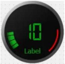 Picture 71: Circular Bar Picture 71: Circular Bar | Circular Bar |
Table 11: Special Property -4
User Manual. EN PROOP 02 V06_1019
| Name Function Used Elements | ||
| Threshold | Defines the beginning of the threshold value.The image of the down limit arc as in Picture-42 above is red. | Analogmeter,Circular Bar,Tank |
| Bar Size Defines size of the circular bar.wCircular Bar | ||
| Cover Glass Enabled | When circular bar is used, this field actives.It shines on circular bar. | Circular Bar |
| Enable Threshold | If the “enabled threshold” is enabled, it displays on the screen.If the “enabled threshold” isn't enabled, it hides. | Circular Bar |
| NumTicks | If the tank element tool is used, this field actives.Divides the value between the minimum and maximum values as shown in Picture-43.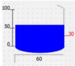 Picture 72: Tank Picture 72: Tank | Tank |
| showCurrentDate/Time | If the wall clock is used, this field actives.If this field is selected, the current date/time displays on the screen. | Wall Clock |
| Date/Time | If the wall clock is used, this filed actives.If showCurrentDate/Time isn't selected, the desired date / time value sets. | Wall Clock |
| Day Font, Date Font, Time Font, Digit Font | Sets the font of the object. | Thermometer,Manometer,Wall Clock |
Table 12: Special Property -5
User Manual. EN PROOP 02 V06_1019
| NameDFunctionDUsed Elements | ||
| DigitColor, DateColor, DayColor, TimeColor | Sets the color of the object.The wall clock tool shows in Picture-44 below. Picture 73: Duvar Saati Picture 73: Duvar Saati | Wall Clock |
| digitOffset, dateOffset, dayOffset, timeOffset | Sets the distance from the center of the object. | Thermometer, Manometer, Wall Clock |
Table 13: Special Property -6
User Manual. EN PROOP 02 V06_1019
B.5.8. Visual
Visual properties are used in all element tools.
| Name Function | |
| Visible | If the button tool is used, this field actives.If the “visible” field is selected, it displays or hides of the element tool. |
| Style Sheet | When the icon is clicked on the left, style edit form open.For the element tool view, user can add source image, gradient, add font option. Style code can add to the area where cursor is located. Picture 74: Style Sheet->Edit Style Sheet Picture 74: Style Sheet->Edit Style Sheet |
| Frame Style | If the potentiometer tool is used, this field actives. Picture 75: Potantiometer Options Picture 75: Potantiometer Options |
Table 14: Visual Property -1
User Manual. EN PROOP 02 V06_1019
| Name Function | ||
| Text Displays the desired text. | ||
| Label Element tool is name. | ||
| LabelPosition The label position are the left, right, top, bottom or center. | ||
| Background Color | If the "flat" is enabled in the general section, background color sets of the button tool.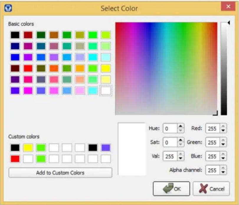 Picture 76: Background Color->Select Color Picture 76: Background Color->Select Color | |
| Foreground Color | When the analogmeter is used, this field actives.Foreground color sets of the analogmeter tool. | |
| Font Style | When "intermittent" is selected, text displays with fixed range. | |
| When "sliding" is selected, marquee displays. | ||
| Font Type Selects the font types. | ||
| Font Color Selects the font color. | ||
| pixlbPicture | [13xw] | If the button tool is used, this field actives.When the icon is clicked on the left, style edit form opens. |
| Picture Alignment | The picture alignment options are horizontally and vertically. | |
Table 15: Visual Property -2
User Manual. EN PROOP 02 V06_1019
| Name Function | ||
| Flat To upload the desired image, the "flat" field must enabled. | ||
| Icon Size Defines the width and height values of the icon. | ||
| Icon When the icon is clicked on the left, style edit form opens. | ||
| Word Wrap If this field is enabled, the text is wrapped where necessary at word-breaks. | ||
| Focus | Focus type options are Nofocus, Tabfocus, Clickfocus, Stringfocus, Wheelfocus. | |
| Font Format Font format options are Richtext, Plaintext, Logtext, Ototext. | ||
| Text Direction | If the multi slider tool is used, this field actives.Text direction options are TopToBottom, BottomToTop. | |
| Orientation | Selects the leftoright or bottomtotop the slider button direction.  Picture 77: Slider Picture 78: Slider Picture 77: Slider Picture 78: Slider | |
| Text Visible | If the multi slider or progress bar tools are used, this field actives.The value displays on the screen as text format. | |
| Alignment | Alignment options are vertical alignment and horizontal alignment. | |
| Text is alignment at the left, right or center on vertically. | ||
| Text is alignment at the top, bottom or horizontal on horizontally. | ||
| Title | If analogmeter 2 and group box is used, this field actives.Text is displays on the screen. | |
| Margin The width of the margin. | ||
| Indent Text indent in pixels. | ||
| Scroll Direction Scroll button direction options are TopToBottom, BottomToTop. | ||
| Tank Color | ... | If the tank tool is used, this field actives. When the icon is clicked on the left, fluid color selects at the tank tool. |
Table 16: Visual Property -3
User Manual. EN PROOP 02 V06_1019
| Name Function | |
| Show Navigation | Show / hide navigation feature in list and graphic elements. |
B.5.9. Geometry
When the gauges and other element tools are used, this section actives.
| Name Function | |
| Geometry | The coordinates of the selected element are determined according to the position on the page. |
| Size Policy, Base Size, Size Increment, Minimum Size, Maximum Size | Determines the minimum and maximum size of the selected element tool. |
Table 17: Geometry Property
B.5.10. Set Value
When the button element is used, this section actives in the property list.
| Name Function | |
| Step Value | |
| Minimum | Minimum and maximum value is determined of the percent value. |
| Maximum | |
| Constant Value | Constant value is set at the element tool. |
Table 18: Set Value Property
B.5.11. Macro
When the button element is used, this section actives in the property list
| Name Function | |
| Before | |
| Pressed | When the before, pressed or release is clicked, opens 'edit makro form'. |
| Release | |
| Script Select Macro | In SQL, it retrieves the data drawn with the query ile SELECT. |
Table 19: Macro Property
User Manual. EN PROOP 02 V06_1019
B.5.12. Frame
When the data entry, shapes and other tools are used, the frame section actives.
| Name Function | |
| Frame Shape | The options are NoFrame, Box, Panel, WinPanel, Hline, Vline, StyledPanel.The frame shapes show in the following order. Picture 79: Frame Shape Picture 79: Frame Shape |
| Frame Shadow | Options are Plain, Raised, Sunken.The frame shadows show in the following order. Picture 80: Frame Shape Picture 80: Frame Shape |
| Line Width Determines the bold of the frame. | |
| Mid Line Width | The field that draws a line horizontally on the element tool and determines the line width. |
Table 20: Frame Property
User Manual. EN PROOP 02 V06_1019
B.5.13. Shape
When the shape tools are used, the shape section actives in the property list.
| Name Function | |
| Line ColorGround Color | The user determines of the desired color or background color for the shape tool. |
| Line Width The user determines of the line width for the shape tool. | |
| Shape | There are options square, arc and triangle of the shape element tool.If arc is drawn, start angle and end angle must determine. Picture 81: Shapes Picture 81: Shapes |
| Start AngleEnd Angle | If the arc is used, this field actives.An arc can draw determining the start and end angles. |
Table 21: Frame Property
B.5.14. Line
Only ruler element tool uses this section.
| Name Function | |
| Rotation | The rotation options are horizontal, vertical, rotation_180 and rotation_270. Picture 82: RulerThe above picture, the rotation of the ruler set to standard and rotation_270 according to the order of the picture. Picture 82: RulerThe above picture, the rotation of the ruler set to standard and rotation_270 according to the order of the picture. Picture 83: RulerThe above picture, the rotation of the ruler set to rotation_90 and rotation_180 according to the order of the picture. Picture 83: RulerThe above picture, the rotation of the ruler set to rotation_90 and rotation_180 according to the order of the picture. |
Table 22: Line Property
B.5.15. Pipe
When the pipe tools are used, the pipe section actives in the property list.
| Name Function | ||
| Background Color | When the icon is clicked on the left, the water(fluid) color determine in the pipe tool. | |
| Rotation | The user select the element tool direction.The options are standard(horizontally) and rotation_90(vertically). | |
| State | This option determines the state of the water(fluid). | |
| If the “disable” is selected, the water(fluid) does not move in the pipe. | ||
| If the “enable” is selected, the water(fluid) moves in the pipe. | ||
| vDirection | The direction of the water(fluid) can selects from left to right or from right to left. The rotation is horizontal. Picture 84: Pipe Picture 84: Pipe | |
The direction of the water(fluid) can selects from top to bottom or from bottom to top. The rotation is vertical. Picture 85: Pipe Picture 85: Pipe | ||
Table 23: Line Property
User Manual. EN PROOP 02 V06_1019
B.5.16. Scale
When the tachometer tools are used, the scale section actives in the property list.
| Name Function | |
| Needle Origin x | If the tachometer is used, this field actives. |
| Needle Origin y | The position define of the needle on the element tool. |
Table 24: Scale Property
B.5.17. Chart
When the chart element tool is used, the chart section actives in the property list.
| Name Function | ||
| Top Background Color, Bottom Background Color, GridColor | The user can make custom color selection on the appeared color picker dialog. | |
| Period | Default values is 1000ms.Graph channels sampling interval time. | |
| Position Scrolls | the active visible area. | |
| Size | Default value is 10000.If the size value increases, it will read more than the X-axis value. | |
| Zoom If the zoom value increases, the graphic will display in detail. | ||
| Xmesh, yMesh | This field is half of the number of grids on the horizontal. | |
| This field is half of the number of grids on the vertical. | ||
| xSubMesh | The 'xSubMesh' divides between both grids on the horizontal. | |
| ySubMesh | The 'ySubMesh' divides between both grids on the vertical. | |
| showGrid | If "showGrid" is enabled, the vertical and horizontal grids will display.If "showGrid" is not enabled, the vertical and horizontal grids will hide. | |
| showScale If the display is selected, the data values will display at the horizontal. | ||
| showLegend If the display is selected, the text title will display of the values.To define the 'text title', right click on the cursor while the cursor is over the chart element tool. More then click the 'edit items' title from open | ||
| window. | |
| Antialiasing Enables the ‘antialiasing’ feature. | |
Table 25: Chart Property

text_image
Change Object Name... Edit Items... Morph into Change Style Sheet... Size Constraints Send to Back Ctrl+K Bring to Front Ctrl+L Cut Ctrl+X Copy Ctrl+C Paste Ctrl+V Select All Ctrl+A Delete LayoutPicture 86: Chart
To edit the chart element tool;
- Right click on the cursor, while the cursor is over the chart element tool.
- Click the 'edit items' title from opened window.
• A new form will open as below.

text_image
Edit Chart Channels humidity Property Value Text humidity translat... ✓ disamb... comme... Read Addr... internal_memory@$0 slaveid 1 address... UnsignedInt16 Minimum 0.000000 Maximum 0.000000 ChannelCo... [No brush, [0, 0, 0] (255)] Style No brush Color [0, 0, 0] (255) Red 0 Green 0 Properties ≥> OK CancelPicture 87: Chart->Edit Chart Channels
•This window edits curves(channels) in the chart.
- On number field 1, curves list and Curve name selects the desired.
• On number field 2, properties edit of the selected chart.
- On number field 3, create a new curve, delete the selected curve, move the curve up or down the list.
B.5.18. Barcode
These properties are used in the Barcode element.
| Name Function | ||
| Barcode Type | It is the type selection property of the Barcode element. Example: CODE 128, QRCODE, EXCODE etc. | |
| Character Length | Specifies the maximum length of the character length of the read or entered value of the element. Characters with more than this number cannot be entered or displayed. | |
| Show Text Show / Hide the text on the element. | ||
| Print Scale The | size of the element to be reduced can be adjusted. | |
| Height | Uses to adjust the line height within the barcode element. | |
| Height Output | ||
| barcodeHeight 20 |  | |
| barcodeHeight 40 |  | |
| White Space | Used to adjust the amount of space left of the barcode element from the edges. | |
| Border Type | Adds a frame to the Barcode element. (Ribbon, Box, etc.) | |
| Border Width Used to adjust the size of the frame edges. | ||
B.6. Element Tree
Lists the used element tools as tree on the form screen.

text_image
Object Sayfa_10 groupBox elabel_2 qelabel_10 qelabel_8 qelabel_9 qtSvgSlideSwitch groupBox_2 pushButton pushButton_2 pushButton_3 pushButton_4 pushButton_5 pushButton_6 pushButton_7 pushButton_8 groupBox_3 SVGScrollDial elabel qelabel_11 queslider groupBox_33 EForm QGroupBox QELabel QELabel QELabel QETSvgSlideSwitch QGroupBox QEPushButton QEPushButton QEPushButton QEPushButton QEPushButton QEPushButton QEPushButton QEPushButton QEPushButton QEPushButton QEPushButton QEPushButton QEPushButton QEPushButton QEPushButton QEPushButton QEPushButton QESlider QGroupBoxPicture 88: Element Tree
C) Macro
For more information, you can examine Macro Wizard window.
C.1. Variable Types
| Operator | global |
| Comment | Defines a global variable to use in all of macro code. |
| Example | global var1; //A global variable named var1 was created.var1 = 5; //Variable 5 is assigned to variable var1 |
| Operator | local |
| Comment | Defines a variable to use in the function it contains. |
| Example | local var1; // A local variable named var1 was created.var1 = 10; //Variable 10 is assigned to variable var1. |
| Operator | n |
| Comment | Volatile variable specifies at assigned in the internal memory |
| Example | 10 //The volatile variable number 10 is//specifies to address |
| Operator Mn | |
| Comment Non-volatile specifies at addressing in the internal memory. | |
| ExampleM10 //The non-volatile variable number 10 is//specifies to address | |
| Operator {device name}device id@n | |
| Comment Specifies the variable assignment at the desired address of the connected device. | |
| Example AMF}1@10 //This usage specifies the address 10 of the// device named Amf with device ID 1. | |
C.2. Arithmetic Operators
| Operator + | |
| Comment Used to the sum of two values. | |
| Example | var1 = 10 + 20; //Adds 10 to 20 and assigns the result to //variable var1. |
| Operator - | |
| Comment Used to the subtract of the two values. | |
| Example var1 = 20 - 10; //Subtracts the value of 10 from 20 and//assign the result to variable var1 | |
| Operator | * |
| Comment | Used to multiplication of the two values. |
| Example | var1 = 10 * 20; //Multiplies the value 10 by 20 and assign //the result to variable var1 |
| Operator | / |
| Comment | Used to division of the two values. |
| Example | var1 = 20 / 10; //Divides 20 by 10 and assign the result to //variable var1 |
| Operator | = |
| Comment | Used to assign value at variable or assign value of the other value at variable. |
| Example | var1 = var2 //Assign the value of var2 to var1 |
| Operator | sqrt(n) |
| Comment | Used to find square root of the value. |
| Example | var1 = sqrt(9); //The square root of the value 9 is assigned //to var1. |
C.3. Boolean Operators
Boolean operators are used with the if and while operators and return the comparison results as true or false.
| Operator | < |
| Comment | Returns true if the value to the left of the operator is less than right, false otherwise. |
| Example | if var1 < 10 //if the value var1 is less than 10 |
| Operator | > |
| Comment | Returns true if the value to the left of the operator is greater than right, false otherwise. |
| Example | if var1 > 10 //if var1 is greater than 10//if the value var1 is greater than 10 |
| Operator | <= |
| Comment | Returns true if the value to left of the operator is less than or equal to right, false otherwise. |
| Example | if var1 <= var2 //if the value var1 is less than or equal to //var2 |
| Operator | >= |
| Comment | Returns true if the value to left of the operator is greater than or equal to the right, false otherwise. |
| Example | if var1 >= var2 //if the value var1 is greater than or equal //to var2 |
| Operator | == |
| Comment | Returns true if the value to left of the operator is equal to right, false otherwise. |
| Example | if var1 == var2 //if the value var1 is equal to var2 |
| Operator | != |
| Comment | Returns true if the value to left of the operator isn't equal to right, false otherwise. |
| Example | if var1 != var2 //if the value var1 isn't equal to var2 |
| Operator | || |
| Comment | Returns true if the condition on the left of the operator or the condition on the right is true, false otherwise. |
| Example | if var1 < 5 || var2 > 5 //if the value var1 is less than 5 or //greater than 5 |
| Operator | && |
| Comment | Returns true if the condition on the left of the operator and the condition on the right is true, false otherwise. |
| Example | if var1 == 0 && var2 != 2 //if the value var1 is equal to 0 and //if the value var1 isn't equal to 2 |
C.4. Logical Operators
The conditional operator "if" compares using the boolean operators and executes the desired code columns.
if expression1
statement1
else
statement2
endif;
If expression1 is true, statement1 will be executed.
If expression2 is false, it will run expression2.
End if should be placed end of.
Example:
if var1 == 0 // if var1 is equal to 0
var2 = 10; // var2 is equal to 10
else // if var1 not equal to 0
var2 = 20; // var2 is equal to 20
endif; // end
The conditional loop operator "while" compares using the boolean operators and executes the code column in a loop according to the specified condition.
while expression
...
endw;
While loop executes the code into the loop as long as expression1 is true.
endw should be placed end of.
Example:
while var1 != 100 //as long as the value of var1 is not 100
var2 = var2 + 1; //increase var2 by 1
var1 = var2; //equal var2 to var1
endw; //end
The loop operator "for" executes the code column in a loop as the specified number of times.
for variable1 = value1 to value2 do
...
endfor;
When the for loop is used with to, the value of variable 1 is initialized equal to value1.
Increase by 1 in each loop.
The for loop is executes in a loop until it reaches value2.
endfor should be placed end of.
for variable1 = value1 downto value2 do
...
Endfor;
When the for loop is used with downto, the value of variable1 is started equal to value1.
Decrease by 1 in each loop.
The for loop is executes in a loop until it reaches value2.
endfor should be placed en of.
Example:
for var1 = 0 to 100 do    //var1 loop from 0 to 100
var2 = var2 + 1;    //increase var2 by 1 at the each loop
endfor;    //end
for var1 = 50 downto 0 do    //var1 loop from 50 to 0
var2 = var2 - 1;    //decrease var2 by 1 at the each loop
endfor;    //end
C.5. Others
| Operator func - endf | |
| Comment | Used to definition a function. |
| Example | func function1() //define function1...endf //end |
| Operator call | |
| Comment | Used to call/execute a function. |
| Example | call function1(); //execute/call function1 |
| Operator sleep | |
| Comment | Used to wait for a period of time in milliseconds. |
| Example | sleep(1000); //wait 1000 millisecond |
| Operator endp | |
| Comment | Comes at the end of the macro code and specifies that the macro code ends here. |
| Operator getsystick | |
| Comment | Represents an increasing value in internal memory as milliseconds. |
| Example | if(getystick() - 10 > 5000) //Increase a variable by 1 //for 5000 msa = a + 1;10 = getsystick();endif; |
| Operator getsystime | |
| Comment | Retrieves system timing information. |
| Example | 0 = getsystime(); //system time is assigned //to0. |
| Operator getsystouch | |
| Comment | is used to get elapsed time since last interaction with screen. |
| Example | $0 = getsystouch(); //get elapsed time since last //touch |
| Operator writeonce | |
| Comment | is used to shift address and write value. |
| Example | for i = 0 to 2 do //addresses are shifted writeonce(10, i) = getonce(20,i); //as much as i's value endfor; //then read and written |
| Operator getonce | |
| Comment | is used to shift address and read value. |
| Example | for i = 0 to 2 do //addresses are shifted writeonce(10, i) = getonce(20,i); //as much as i's value endfor; //then read and written |
| Operator writesync | |
| Comment | is used to write value synchronously. |
| Example | varMod1 = //if writesync can write writesync("modbus1@40001", 1); //value it returns 1 if //not -1 |
| Operator putbuf - writebuf | |
| Comment | putbuf puts values to buffer and writebuf sends. |
| Example | varBuf = mw_putbuf("modbus1@40001",1); //if writebuf can varBuf = mw_putbuf("modbus1@40002",2); //send buffer varMod1 = mw_writebuf(); //successfully //returns 1 if not -1 |
| Operator putbuf - writebufsync | |
| Comment | putbuf puts values to buffer and writebufsync writes. |
| Example | varBuf = mw_putbuf("modbus1@40001",1); //if writebuf can varBuf = mw_putbuf("modbus1@40002",2); //write buffer varMod1 = mw_writebuf(); //successfully //returns 1 if not -1 |
| Operator loadrecipe | |
| Comment | is used to call prepared recipes. |
| Example | loadrecipe(“Dough”,”Bread”); //This operation has //“Dough” named recipe //and "bread" named //recipe data |
| Operator resetcomm | |
| Comment | is used to reset communication. |
| Example | resetcomm(“modbus”,”1”); //reset modbus device |
C.6. Type Conversion
This is a feature that helps to convert various data types between each others. It is used with codes in macro page.
Conversions are like:
(int) : integer conversion.
(double) : double conversion.
(float) : float conversion.
In this example, value of \$1 address is converted to double value and written to 40001 address of modbus1 device.
func main()
modbus1@40001 = (double) \$1;
endf endp
C.7. Macro Wizard
Macro Wizard is a help window which lists all macro commands and it has explanations and examples too. Thanks to this window, macro commands can be prepared in accordance with its format and added to macro code window.
Macro Wizard can be reached with wthis button on macro window.
First drop down list includes group names of commands and the second includes commands. Command can be selected with "Select" button and it's explanation and example can be reached with "?" button. After selection a command, if it has variables, they are listed and for variable selection, cells being under "Variable Selection" column should be clicked and edited. When all variables are edited, "OK" button is clicked. Prepared command is added to cursor's position on macro code window.

text_image
Proop Macro Arithmetic Commands + ? Select Format var1 = var2 + var3; Variable Name Variable Selection Var1 $0 Var2 $1 Var3 10 OK CancelPicture 89: Macro Wizard
| Models | PROOP Types | COM2 RS-485 | COM3 RS-232 | COM4 RS-232 | ETH | Digital Input/Output | Analog Input/Output | USB Host | USB Server |
| 7" Model Types | 7L | ✓ | ✓ | ✓ | ✓ | ✓ | |||
| 7L.E | ✓ | ✓ | ✓ | ✓ | ✓ | ✓ | |||
| 7C | ✓ | ✓ | ✓ | ✓ | ✓ | ✓ | |||
| 7C.E | ✓ | ✓ | ✓ | ✓ | ✓ | ✓ | ✓ | ||
| 10" Model Types | 10L | ✓ | ✓ | ✓ | ✓ | ✓ | |||
| 10L.E | ✓ | ✓ | ✓ | ✓ | ✓ | ✓ | |||
| 10C | ✓ | ✓ | ✓ | ✓ | ✓ | ✓ | |||
| 10C.E | ✓ | ✓ | ✓ | ✓ | ✓ | ✓ | ✓ | ||
| 10P | ✓ | ✓ | ✓ | ✓ | ✓ | ✓ | ✓ | ||
| 10P.E | ✓ | ✓ | ✓ | ✓ | ✓ | ✓ | ✓ | ✓ |
Table 26: PROOP Model List
User Manual. EN PROOP 02 V06_1019
E) C Code
See the subtitles for C code functions and writing.
E.1. Main Template
The main function template is shown in the picture below. When the button indicated by the red field is pressed, the main function block is added to the code writing area.

text_image
#includeE.2. C Code Functions
| Function getData() | ||
| Comment | It waits for the data to be read by communication and is read successfully 0 returns -1 on error. | |
| Usage | int getData(void *data,const char * strAddress,unsigned int offset,int bytesize); | |
| Example | char led;getData(&led, "0.0",0,1) | // &led -> data//0.0 -> read address// 0 -> offset// 1 -> bytesize |
| Function setData() | ||
| Comment | It waits for data to be written by communication, and returns 0 if successfully written. | |
| Usage | int setData(void *data,const char * strAddress,unsigned int offset,int bytesize); | |
| Example | char led;setData(&led, "0.0",0,1); | // &led -> data//0.0 -> read address// 0 -> offset// 1 -> bytesize |
| Function getDataAsync() | ||
| Comment | It does not wait for the data to be read by communication, it uses the previously read value. If read successfully, 0 returns -1 on error; | |
| Usage | int getDataAsync (void *data,const char * strAddress,unsigned int offset,int bytesize); | |
| Example | uint64_t uval;getDataAsync(&uval, "1",0,sizeof(uval)); | // &uval -> data//1 -> read adsress// 0 -> offset// sizeof(uval) -> bytesize |
| Function enhancing() | ||
| Comment | It does not wait for the data to be written by communication, it assigns the data to be written to the queue. Even if there is a communication error, it always returns 0 unless there is a system error. | |
| Usage | int enhancing(void *data,const char * strAddress,unsigned int offset,int bytesize); | |
| Example | uint64_t uval;setDataAsync(&uval, "1",0,sizeof(uval)); | // &uval -> data//1 -> read adsress// 0 -> offset// sizeof(uval) -> bytesize |
E.3. C Code Function Parameters
| Parameter Function | |
| *data Pointer | address of write or read data. |
| *strAddress | “devicename@address”The input format of the internal addresses and the number of bytes to be used as bytesize are as follows;“0”: 8“0.0”: 1“M0”: 8“M0.0”: 1“S0”:S Since addresses starting with $ S2 are of type int, 4 must be entered asbytesize. |
| Bytesize values to be used for Modbus protocol; Holding and Input register addresses 2, 1 for other input and output bits. | |
| *offset wAddress | offset value. |
| *bytesize wThe | number of bytes of data to be written or read. |
E.4. C Code Examples
Example -1: Changing the status of the LED element

text_image
Change Led StatePicture 90: Changing Led State
- Step 1: One button and led element is added to the working area.
- Step 2: On the Properties menu, under C code, click on Release and type C code in the form that opens.
| Code | |
| Pressed | |
| Released | #include <proop.h> \nint main()\n{\n\n... |
- Step 3: "Released", the macro code is shown in the following table. If the LED status is 0, the LED turns off, if it is 1, the LED turns on.
| Using Button Execute Macro Code Result | ||
| Change Led StateReleased button | #includeint main(){char led;if (!getData(&led, "0.0", 0, 1))led = !led;setData(&led, "0.0", 0,1);}return 0;} | If status 1;Change Led Stateif status 0;Change Led State |
Example -2: Showing Time Value
It is an application that shows the system clock and led statuses on the screen with C functions from two different addresses in the main C code and periodic C code editing forms. The screenshot of the application is as follows.

text_image
Proop Zaman / Clock Show Number 1 3946431890 Show Number 2 3946431890 LED 1 Buton LED 2 BACK NEXTPicture 91: Example-2 Screenshot
Element addresses must be entered as given in the table below.
| Element Name Address Type Write | Address Read Address | |
| Show Number 1wUnsignedInt64w-wmodbus@30001 | ||
| Show Number 2wUnsignedInt64w-wmodbus@30002 | ||
| ButtonwBitwmodbus@40001.1w- | ||
| LED 1wBitw-wmodbus@40001.2 | ||
| LED 2wBitw-wmodbus@40001.3 |
Main C Code
#include <proop.h>
#include <time.h>
#include <stdint.h>
#ifdef _WIN32
#include <windows.h>
#endif

void musleep(unsigned long usec)
{
#ifndef _WIN32
    struct timespec res;
    res.tv_sec = usec / 1000000;
    res.tv_nsec = (usec * 1000) % 1000000000;
    clock_nanosleep(CLOCK_REALTIME, 0, &res, NULL);
#else
    Sleep(usec / 1000);
#endif

uint64_t getClock()
{
    uint64_t val;
#ifdef _WIN32
    struct timespec sNow;
    clock_gettime(CLOCK_REALTIME, &sNow);
    val = sNow.tv_sec * 1000 + sNow.tv_nsec / 1000000;
#else
    val = GetTickCount();
#endif
    return val;
}

uint64_t uval, uval2;

int main()
{
char led = 0;

//if(getClock() - uval > 500)
{
    uval = getClock();

    if (!getData(&led, "modbus@40001.1", 0, 1)) {
    setData(&led, "modbus@40001.2", 0, 1);
    }
}

uval2 = getClock();
setDataAsync(&uval2, "modbus@30002", 0, sizeof(uval2));

return 0;
}
Periodic C Code
#include <proop.h>
#include <time.h>
#include <stdint.h>
#ifdef _WIN32
#include <windows.h>
#endif

void musleep(unsigned long usec)
{
    #ifndef _WIN32
    struct timespec res;
    res.tv_sec = usec / 1000000;
    res.tv_nsec = (usec * 1000) % 10000000000;
    clock_nanosleep(CLOCK_REALTIME, 0, &res, NULL);
    #else
    Sleep(usec / 1000);
    #endif
}
uint64_t getClock()
{
    uint64_t val;
    #ifndef _WIN32
    struct timespec sNow;
    clock_gettime(CLOCK_REALTIME, &sNow);
    val = sNow.tv_sec * 1000 + sNow.tv_nsec / 1000000;
    #else
    val = GetTickCount();
    #endif
    return val;
}

uint64_t uval, uval2;

int main()
{
    char led = 0;

    if (getClock() - uval > 500) {
    uval = getClock();
    //Led 2 status changes according to time.
    if (!getData(&led, "modbus@40001.3", 0, 1)) {
    led = !led;
    setData(&led, "modbus@40001.3", 0, 1);
    }
    }

    uval2 = getClock();
    setDataAsync(&uval2, "modbus@30001", 0, sizeof(uval2));
    return 0;
}
Example -3 :
An example of displaying the counter value on the screen using the label element using the C function.
Program screenshot is as follows.

text_image
Counter 0,000 Print Value 0,000 BACK NEXTPicture 92: Example-3 Screenshot
Element addresses must be entered as given in the table below.
| Element Name Address Type Write | Address Read Address | |
| CounterwDoublewinternal_memory@3w- | ||
| Button(Print Value) | -w-w- | |
| LabelwDoublew-winternal_memory@4 | ||
Press the "Print Value" button, then release. The following c code is executed.
| Released C Code |
| # include <proop.h> |
| int main( ) |
| { |
| double dval; |
| if (!getData(&dval, "3", 0, sizeof(dval))) |
| setsData(&dval, "4", 0, sizeof(dval)); |
| } |
| return 0; |
| } |
Example -4:
This example describes the C code programming of multiple writes and Page changes.
The screenshot of the program is as follows.

text_image
Proop Multi Write 0,000 0,000 0,000 BACK Change Page NEXTPicture 93: Example- 4 Screenshot
Element addresses are entered as given in the following table.
| Element Name Address Type Write | Address Read Address | |
| Multi WritewDoublewinternal_memory@3w- | ||
| Change Pagew-w-w- | ||
| Label 1wDoublew-winternal_memory@4 | ||
| Label 2wDoublew-winternal_memory@5 | ||
| Label 3wDoublew-winternal_memory@6 | ||
With multiple writing operations, three different addresses are written at the same time. The value at \4 is taken, and the value at \4 is printed on addresses \5, \6, respectively.
Multi Write Released C Code
#include <proop.h>
int main()
{
    double dval[3];
    if (!getData(&dval, "$4", 0, sizeof(dval))) {
    dval[0] = dval[0] + 1;
    dval[1] = dval[1] + 1;
    dval[2] = dval[2] + 1;
    setData(&dval, "$4", 0, sizeof(dval));
    }
    return 0;
}
Change Page Released C Code
#include <proop.h>
int main()
{
    int ival = 1;
    setData(&ival, "$S2", 0, sizeof(ival));
    return 0;
}
F) PROOP Access
F.1. Models
| ProBlackopEco | Display Type | Display Colors | Display Resolution | Luminance [Cdm2] | Device Panel Dimensions | Ctrl-Du | Weight |
| Piooa back-4.aco | 4.3" TFT 260K colors | 480x272 | 530 | 153x105:50 mm | 143x97mm | 350gr | |
| Piooa back-5.aco | 5" TFT | 260K colors | 800x480 | 330 | 153x105:50 mm | 143x97mm | 350gr |
| Piooa back-7.aco | 7" TFT | 260K colors | 800x480 | 300 | 206x152:50 mm | 196x142mm | 700gr |
| ProopLite | Display Type | Display Coors | Display Resolution | Lumance Cdm2i | Ethernet (10/100 Mbps) | Witt IEEE 802.11big-n |
| Pioup-7L w | 7" TFT | 260K color | 800x480 | 300 | 1x | |
| Pioup-7L E | 7" TFT | 260K color | 800x480 | 300 | 1x | |
| Pioup-7L Ewi | 7" TFT | 260K color | 800x480 | 300 | 1x | 1x |
| Pioup-10L | 10.1" TFT | 16M color | 1024x600 | 270 | ||
| Pioup-10L w | 10.1" TFT | 16M color | 1024x600 | 270 | 1x | |
| Pioup-10L E | 10.1" TFT | 16M color | 1024x600 | 270 | 1x | |
| Pioup-10L Ew | 10.1" TFT | 16M color | 1024x600 | 270 | 1x | 1x |
| ProBlackopLite | Display Type | Display Co. ops | Display Resolution | Luminance Cdm2 | Ethernet (10:100 Mbps) | Will IEEE 802.11bign |
| Proop-A7acwi7 | TFT | 260K color 800x480 | 300 | 1x | ||
| Proop.black-7LE | TFT | 260K color | 800x480 | 300 | 1s | |
| Proop.black-7LEw | TFT | 260K color | 800x480 | 300 | 1s | 1x |
| Proop.black-10L | 101TFT | 16M color | 1024x600 | 270 | ||
| Proop.black-10Lw | 101TFT | 16M color | 1024x600 | 270 | 1x | |
| Proop.black-10LE | 101TFT | 16M color | 1024x600 | 270 | 1s | |
| Proop.black-10LEw | 101TFT | 16M color | 1024x600 | 270 | 1s | 1x |
| ProopProcess | Ethernet(10/100 Mbps) | Wili(IEEE 802.116/g/n) | Digital Inputs | Digital Outputs(Transistor) | Analogus Inputs | Analogue Outputs |
| Proop-10P.0.D5.D4.AC AC | 5s | 4x | 2x4...20mA | 2x4...20mA | ||
| Proop-10P.wi.D5.D4.AC AC | 1x | 5s | 4x | 2x4...20mA | 2x4...20mA | |
| Proop-10P.E D5.D4.AC AC | 1s | 5s | 4x | 2x4...20mA | 2x4...20mA | |
| Proop-10P.Ewi.D5.D4.AC AC | 1s | 1x | 5s | 4x | 2x4...20mA | 2x4...20mA |
| Proop-10P.E2 D5.D4.AC AC | 2s | 5s | 4x | 2x4...20mA | 2x4...20mA | |
| Proop-10P.E2wi.D5.D4.AC AC | 2s | 1x | 5s | 4x | 2x4...20mA | 2x4...20mA |
PROOP Builder
| ProBlackopProcess | Ethernet(10/100 Mbps) | Wit(IEEE 802.11-digit) | Digital Inputs | Digital Outputs(Transistor) | Analogus Inputs | Analogue Outputs |
| Piooc black -10P.O D5.D4.AC.AC | 5s | 4x | 2x 4...20 mA | 2x 4...20 mA | ||
| Piooc black -10P w1.D5.D4.AC AC | 1x | 5s | 4x | 2x 4...20 mA | 2x 4...20 mA | |
| Piooc black -10P.E.D5.D4.AC.AC | 1s | 5s | 4x | 2x 4...20 mA | 2x 4...20 mA | |
| Piooc black -10P Ew1.D5.D4.AC AC | 1s | 1x | 5s | 4x | 2x 4...20 mA | 2x 4...20 mA |
| Piooc black -10P E2.D5.D4.AC AC | 2s | 5s | 4x | 2x 4...20 mA | 2x 4...20 mA | |
| Piooc black -10P E2 w1.D5.D4.AC AC | 2s | 1x | 5s | 4x | 2x 4...20 mA | 2x 4...20 mA |
| ProopControl | Display Type | Display Colors | Display Resolution | Luminance Cd^^2 | Ethernet [10+100 Maps] | W | IEEE 602.11bigm) | Digital input | Digital Outputs (Transistor) |
| Proop-7C | 7^1 TFT 260K color | 500x480 | 300 | 1x | 4x | 4x | ||
| Proop-7C w | 7^1 TFT | 260K color | 500x480 | 300 | 4x | 4x | ||
| Proop-7C E | 7^1 TFT | 260K color | 500x480 | 300 | 1x | 4x | 4x | |
| Proop-7C E2 | 7^1 TFT | 260K color | 500x480 | 300 | 2x | 4x | 4x | |
| Proop-7C Ew | 7^1 TFT | 260K color | 500x480 | 300 | 1x | 1x | 4x | 4x |
| Proop-7C E2w | 7^1 TFT | 260K color | 500x480 | 300 | 2x | 1x | 4x | 4x |
| Proop-10C | 10 1^11 TFT | 16M color | 1024x600 | 270 | 5x | 4x | ||
| Proop-10C w | 10 1^11 TFT | 16M color | 1024x600 | 270 | 1x | 5x | 4x | |
| Proop-10C E | 10 1^11 TFT | 16M color | 1024x600 | 270 | 1x | 5x | 4x | |
| Proop-10C Ew | 10 1^11 TFT | 16M color | 1024x600 | 270 | 1x | 1x | 5x | 4x |
| ProBlackopControl | Display Type | Display Colors | Display Resolution | Luminance Cd^TM | Ethernet [10/100 Maps] | W [IEEE 802.11bigm] | Digital inputs | Digital Outputs (Transistor) |
| Proof black-7C | 7^11 TFT | 260K color | 500x480 | 300 | 1) | 4) | 4) | |
| Proof black-7C w | 7^11 TFT | 260K color | 500x480 | 300 | 4) | 4) | ||
| Proof black-7CE | 7^11 TFT | 260K color | 500x480 | 300 | 1x | 4) | 4) | |
| Proof black-7CE2 | 7^11 TFT | 260K color | 500x480 | 300 | 2x | 4) | 4) | |
| Proof black-7CEw | 7^11 TFT | 260K color | 500x480 | 300 | 1x | 1) | 4) | 4) |
| Proof black-7CE2w | 7^11 TFT | 260K color | 500x480 | 300 | 2x | 1) | 4) | 4) |
| Proof black-10C | 10 1" TFT | 15M color | 1024x600 | 270 | 5) | 4) | ||
| Proof black-10C w | 10 1" TFT | 15M color | 1024x600 | 270 | 1) | 5) | 4) | |
| Proof black-10CE | 10 1" TFT | 15M color | 1024x600 | 270 | 1x | 5) | 4) | |
| 10 1" TFT | 15M color | 1024x600 | 270 | 1x | 1) | 5) | 4) |
User Manual. EN PROOP 02 V06_1019
| Proop-I/O | Digital Inputs | Digital Outputs | Analogue Outputs Analogue | |
| Proop-10.P.2 2.1.3 1.1 | 8: Digital | 8x 1A Transisto+V | 5: P<100 [-200...650°C] | 2x 0+4...20 mAdc |
| Proop-10.P.2 2.1.3 2.1 | 8: Digital | 8x 1A Transisto+V | 5x 0+4...20 mAdc | 2x 0+4...20 mAdc |
| Proop-10.P.2 2.1.3 3.1 | 8: Digital | 8x 1A Transisto+V | 5x 0...10Vdc | 2x 0+4...20 mAdc |
| Proop-10.P.2 2.1.3 4.1 | 8: Digital | 8x 1A Transisto+V | 5x 0...50mV | 2x 0+4...20 mAdc |
| Proop-10.P.2 2.1.3 1.2 | 8: Digital | 8x 1A Transisto+V | 5: P<100 [-200...650°C] | 2x 0...10Vdc |
| Proop-10.P.2 2.1.3 2.2 | 8: Digital | 8x 1A Transisto+V | 5x 0+4...20 mAdc | 2x 0...10Vdc |
| Proop-10.P.2 2.1.3 3.2 | 8: Digital | 8x 1A Transisto+V | 5x 0...10Vdc | 2x 0...10Vdc |
| Proop-10.P.2 2.1.3 4.2 | 8: Digital | 8x 1A Transisto+V | 5x 0...50mV | 2x 0...10Vdc |
F.2. View Panel
The front face of the PRO Operator Panel is as in Picture-61 below and the leds on. Leds are numbered and explained in Table-27.

gauge
| Parameter | Value | | :--- | :--- | | V12: | 400 V | | PF1: | 0.80 | | P1: | 18 kW | | Q1: | 14 kVar | | S1: | 23 kVA | | V23: | 400 V | | PF2: | 0.80 | | P2: | 18 kW | | Q2: | 14 kVar | | S2: | 23 kVA | | V31: | 400 V | | PF3: | 0.80 | | P3: | 18 kW | | Q3: | 14 kVar | | S3: | 23 kVA | | le: | 0 A | | ΣP: | 54 kW | | ΣQ: | 42 kVar | | Events Settings | 57.0 Hz 66.0 Hz 75.0 Frq 1000 kWh 100 kVArh | | Home Mains Generator Engine I/O Alarms Events Settings 150 200 250 50 100 250 V1 240 360 120 400 0 11 Power COM CPU PWMPicture 94: PROOP-Front View
| 1 COM | Communication led with PLC |
| 2 CPU | Displays the current state of the CPU. |
| 3 PWR | An energy led. |
Table 27: PROOP-Front View
User Manual. EN PROOP 02 V06_1019
The back side of PROOP is different in the models.
The back view of the panels has been examined in two different ways as PROOP 7" Models and PROOP 10" Models.
The back of the PROOP 7" models is as shown in Picture-61 below.
Inputs are numbered and inputs numbered in Table-28 are explained.

text_image
Diagram of a network device rear panel with labeled ports and connectors, showing green connectors, I/O port, and terminal blocks.Picture 95: PROOP 7" Back
| 1 | Energy | 6 | Digital Inout/Output |
| 2 | COM1 | 7 | Ethernet |
| 3 | COM2-COM3 | 8 | USB Device |
| 4 | COM4 | 9 | USB Host |
| 5 | Not use |
Table 28: PROOP 7" Inputs
The back of the PROOP 10" models is as shown in Picture-62 below.
Inputs are numbered and inputs numbered in Table-29 are explained.

text_image
Diagram of a network device rear panel with labeled ports and connectors, showing green connectors and terminal blocks.Picture 96: PROOP 10" Back
| 1 | Energy | 7 | Analog Input |
| 2 | Out of use | 8 | Analog Output |
| 3 | COM1-COM2 | 9 | Ethernet |
| 4 | COM3 | 10 | USB Device |
| 5 | COM4 | 11 | USB Host |
| 6 | Out of use |
Table 29: PROOP 10" Inputs
User Manual. EN PROOP 02 V06_1019
F.2.1. Pin Connections
PROOP 7" Model and PROOP 10" Model, the terminals used on the back are different and the pin connections are different.
The different terminals pin connections with PROOP 7" and PROOP 10" terminals are described under separate headings.
F.2.1.1. Supply

text_image
24VDC--- + - - 1 2 3 Inputs + - ⊥Table 30: Supply Connections
F.2.1.2.COM4

text_image
2 3 5 8 7 Inputs 2--Rx 3--Tx 5--GND 7--RTS 8--CTSTable 31: COM4 Pin Connections
F.2.2. Pin Connections in PROOP 7" Models
F.2.2.1.COM1

text_image
COM1: RS-422 Rx+ Rx- Tx+ Tx- 7 8 9 10 Inputs Rx+ Rx- Tx+ Tx-Table 32: COM1 Pin Connections
F.2.2.2. COM2-COM3

text_image
COM2: RS-485 COM3: RS-232 A B GND Rx Tx GND 11 12 13 14 15 16 Inputs A B GND Rx Tx GNDTable 33: COM2- COM3 Pin Connections
F.2.2.3. Digital Inputs/Outputs
 |c|c|c|c|c|c|c27 & 26 & 25 & 24 & 23 & 22 & 21 & 20 & 19 & 18 & 17 \- & DO4 & DO3 & DO2 & DO1 & DO+ & DI4 & DI3 & DI2 & DI1 & +/- \ & DI |c|c|c|c|c|c|c27 & 26 & 25 & 24 & 23 & 22 & 21 & 20 & 19 & 18 & 17 \- & DO4 & DO3 & DO2 & DO1 & DO+ & DI4 & DI3 & DI2 & DI1 & +/- \ & DI | Input | Comment | Connection Scheme |
| DO- | DigitalOutputSupply- |  | |
| DO4 | DigitalOutputs | ||
| DO3 | |||
| DO2 | |||
| DO1 | |||
| DO+ | DigitalOutputSupply+ | ||
| DI4 | DigitalInputs |  | |
| DI3 | |||
| DI2 | |||
| DI1 | |||
| +/- | NPN / PNPSelection ofDigitalInputs |
Table 34: Digital Input/Output Pin Connection
User Manual. EN PROOP 02 V06_1019
F.2.3. Pin Connections PROOP 10" Models
F.2.3.1. COM1-COM2

text_image
COM1: RS-422 COM2: RS-485 Rx+ Rx- Tx+ Tx- GND A B GND 7 8 9 10 11 12 13 14 Inputs Rx+ Rx- Tx+ Tx- GND A B GNDTable 35: COM1- COM2 Pin Connections
F.2.3.2.COM3

text_image
COM3: RS-232 Rx Tx GND 15 16 17 Inputs Rx Tx GNDTable 36: COM3 Pin Connections
F.2.3.3. Analog/Digital Inputs
 | Inputs | Comment Connection Scheme | |
| AI2- | Analog Input2- |  | |
| AI2+ | Analog Input2+ | ||
| AI1- | Analog Input1- | ||
| AI1+ | Analog Input1+ | ||
| DI5 | Digital Inputs |  | |
| DI4 | |||
| DI3 | |||
| DI2 | |||
| DI1 | |||
| +/- | NPN / PNPSelection ofDigital Inputs | ||
Table 37: Analog Inputs Pin Connections
User Manual. EN PROOP 02 V06_1019
F.2.3.4. Analog/Digital Outputs
| Inputs | Comment Connection Scheme | ||
| AO+ | Analog Output Supply + |  | |
| AO- | Analog Output Supply - | ||
| AO2 | Analog Outputs | ||
| AO1 | |||
 | DO- | Digital Output Supply - |  |
| DO4 | Digital Outputs | ||
| DO3 | |||
| DO2 | |||
| DO1 | |||
| DO+ | Digital Output Supply + | ||
Table 38: Analog Outputs Pin Connections
User Manual. EN PROOP 02 V06_1019
F.2.4. Internal I/O Address Definitions
| Device Type Format Range | |
| Digital Input %IXn.k n: 0-0 k: 0-4 | |
| Digital Output %QXn.k n: 0-0 k: 0-3 | |
| Analog Input %IWn n: 0-1 | |
| Analog Output %MWn n: 0-1 |
Table 39: Internal Input / Output Address Definitions
F.2.5. Internal Memory Address Definitions
| Device Type Format Range | ||
| Volatile Memory n | n: 0-65535 | |
| Non-Volatile Memory | Mn | n: 0-65535 |
| Volatile Memory Bit | n.k | n: 0-65535 k: 0-15 |
| Non-Volatile Memory Bit | Mn.k | n: 0-65535 k: 0-15 |
| Internal Settings | $Sn | n: 0-65535 |
Table 40: Internal Memory Addresses
User Manual. EN PROOP 02 V06_1019
F.3. Supported Communication Protocols
Protocols supported by PROOP are addressed.
Supported protocols are listed in the table below.
| Brand Protocols | |
| 1 MO | DBUS Modbus-RTU |
| 2 MO | DBUS Modbus-ASCII |
| 1 MO | DBUS Modbus TCP/IP |
| 2 MO | DBUS Modbus-ASCII(Slave) |
| 1 MO | DBUS Modbus-RTU(Slave) |
| 2 MO | DBUS Modbus TCP/IP(Slave) |
| 3 SIEMENS S7-200(PPI) | |
| 4 SIEMENS S7-300(ISOTCP) | |
| 5 SIEMENS S7-400(ISOTCP) | |
| 6 SIEMENS S7-1200(ISOTCP) |
Table 41: Supported Brands
User Manual. EN PROOP 02 V06_1019
F.3.1. MODBUS Master Address Definitions
Address formats and address ranges are listed for devices using the Modbus communication protocol in the table below.
| Device Type Format | Range Type | ||
| Discreate Output Coils | 1000nwn: 1-6 | 5535wRead-Write | |
| Discreate Input Coils | 2000nwn: 0-655 | 35wRead | |
| Input Registers | 3000nwn: 0-65535wRead | ||
| Holding Registers | 4000nwn: 0-65535 | wRead-Write | |
| Holding Bit | 4000n.kwn: 0-65535 k: 0 | -15wRead-Write | |
| Input Bit | 3000n.kwn: | 0-65535 k: 0-15wRead | |
| Holding Registers(Write Multi) | WMn | n: 0-65535wRead-Write |
Table 42: MODBUS-RTU Address Definitions
User Manual. EN PROOP 02 V06_1019
F.3.2. MODBUS Slave Address Definitions
Standard
| Internal Memory Name | Modbus Address Range | Modbus Functions | |
| Start End | |||
| Volatile Memory 40001 42000 | 3,6,16 | ||
| Non-Volatile Memory 42001 44000 | 3,6,16 | ||
| Analog Outputs 44001 44002 | 3,6,16 | ||
| Internal Settings 45001 45500 | 3,6,16 | ||
Extended
| Internal Memory Name | Modbus Address Range | Modbus Functions | |
| Start End | |||
| Volatile Memory 410001 | 420000 3,6,16 | ||
| Non-Volatile Memory 420001 | 430000 3,6,16 | ||
| Analog Outputs 435001 | 435500 3,6,16 | ||
| Internal Settings | 450001 455000 | 3,6,16 | |
| Internal Memory Name | Modbus Address Range | Modbus Functions | |
| Start End | |||
| Analog Inputs | 30001 30002 | 4 | |
| Internal Memory Name | Modbus Address Range | Modbus Functions | |
| Start End | |||
| Digital Outputs | 00001 00004 | 1,5,15 | |
| Internal Memory Name | Modbus Address Range | Modbus Functions | |
| Start End | |||
| Digital Inputs | 10001 | 10004/10005* | 2 |
NOT*: 5th digital input only available on Proop.10P and Proop.10P.E
G) PROOP Upgrade
PROOP device is upgraded to the current version with Usb connection.
You can upgrade firmware with following the steps below.
- http://www.emkoelektronik.com.tr/ Download the update file from the Download Center → Software section of the website.
- Or http://www.proopforum.com/ download the update file from Proop Forum Site Technical Docs → Proop HMI Firmware Update.

text_image
You can also rotate other languages using Google Translate... Powered by Google Translate EMKO Main Corporate Distributors HR Contact search Products Download Center E-Support News & Events Virtual Training User Login Panel User Login Panel Sign Up · Forgot Password? Download Center Software File Search Search User Manuals Measurement & Control Devices Generator Set Controllers Software Brochures Application Notes Measurement & Control Devices Generator Set Controllers File Name Product Upload Date Process PROOP Firmware Test Update PROOP 18 April 2017 Download ↓Picture 97: Access Site For Software Source
- Copy the compressed file 'update.tar.gz' in the downloaded zip file to the main directory of the usb memory.
- Plug the usb memory into the USB port on the back of the device.
- If you cut off the power of the device and you give it again, the installation process will start.
- You can follow the installation process on the device screen as in Picture-65 below.
Update <tar> started, please wait...
emko/runtime/libEmkoHmi.so.1.0.0
emko/runtime/hmi_protocols/libinternal.so
usr/lib/fonts/arial.ttf
Update successful!!!
Picture 98: Software Update
H) HMI Settings
You can follow the steps below to view and edit the Ethernet settings on the PLC screen.
- Drag any of the button elements to the project page you are using in the Proop Builder program.
- To configure the button, select the button type in the button section of the properties list as 'HMI settings' as below.

text_image
Button Type State Type Page Function Auto Repeat Interval Auto Repeat Delay Auto Repeat autoExclusive Checkable Checked + shortcut Set Value Push Button Checkable Set Reset Set Value Set Constant Multi State Increment Decrement HMI Settings- Click on 'online simulation' from online simulation tools.
• Network settings is shown as default tab.
•The screens of the HMI settings are displayed as follows

| Tabs HMI Settings Screens | ||
| Network Settings |  | The device information are IP address, subnet mask, DNS 1 and DNS 2.The user can edit this information.The MAC address can not be edited and is shown as read only. |
| Date & Time |  | Displays the current time and date.The user can edit time and date. |
| System |  | Buzzer: Adjust the buzzer sound.The left button is OFF, The right button is ON. |
| Brightness: Adjust the brightness.The button increases the brightness from left to right and the maximum value is 7.The button decreases from right to left and minimum value is 0. | ||
Picture 99: HMI Settings
User Manual. EN PROOP 02 V06_1019
I) Defining System Settings by Addressing
I.1. Buzzer
To view and edit the PLC buzzer status, you can follow the steps below.
- Drag and drop the Switch 2 element onto the page of the project you are using in the Proop Builder program.
- To edit the Switch 2 element, click on the icon displayed on the right in the properties list->address->write address. w·A new window will open as below.

text_image
Address Watch Device Name internal_memory Label Device Type Internal Settings Memory UnsignedInt16 $S1 1 0....65535 ID 1 OK CANCELPicture 100:Address Watch(Buzzer)
- Select device name 'internal_memory' as above.
- Select the device type 'Internal Settings' and the memory is displayed as '\$S0'.
- Write the deviceID in the ID field and click the "Ok" button.
•The write address field is displayed as follows.

text_image
Property Value Address Read Address Write Address internal_memory@$S0 slaveid 1 addresstype UnsignedInt16- Click on 'online simulation' from the tools.
•The buzzer setting is displayed as below.

text_image
Buzzer : OFF ONPicture 101:Buzzer
I.1.1. Buzzer / PWM Functions
PWM is the technique to change the output voltage by adjusting the period and the duty cycle of a square wave.
The PWM functions are described in the following tables.
| Function setpwmperiod() | |
| Comment | It is a function that holds the total period (T). |
| Usage | setpwmperiod (“Output name D01-D04”, ms duty cycle); // Buzzer periyod(T) 3000 msn |
| Example | setpwmperiod("DO1", 1000); //Set the period time of the PWM signal to 1000msec. |
| Function setpwmdutycycle() | |
| Comment Used to define the duty cycle of the PWM signal. In 1 period slice, how many msec buzzer is “ON tutul is kept. | |
| Duty Cycle 10%Duty Cycle 30%Duty Cycle 50%Duty Cycle 90%Duty Cycle = Pulse Width x 100 / Period | |
| Usage | setpwmdutycycle ("Output name D01-D04", ms); |
| Example | setpwmdutycycle("D01", 500); //The duty cycle of the PWM signal is 500msec. |
Period (T) : It is the time during which a full swing occurs or for a full cycle. Unit is in seconds and inversely proportional to frequency. In this case, the frequency is the number of periods in 1 second T=1/f we can express with the formula. The frequency of a signal with a period of 1 second is 1Hz.
Duty Cycle : The duration of the square wave in position 1.

text_image
Duty PeriodPicture 102: Square Wave Signal
| Function setpwmpulsenumber() | |
| Comment | It is used to define the number of square waves to be produced. If this value is defined as zero, a continuous PWM signal is generated. If a number is entered, only the number of PWM signals defined here is generated. |
| Usage | setpwmpulsenumber(“Output name D01-D04”, pulse period); |
| Example | setpwmpulsenumber(“D01”,5); // After generating 5 pulses, the output is OFF. |
| Fonksiyon | setpwmenable() |
| Comment | Enables or disables PWM operation.Note: The parameters are set before Pwm operation is activated.setpwmperiod("S0", 3000);setpwmdutycycle("S0", 300);setpwmpulsenumber("S0", 0);setpwmenable("S0", 1);The parameters were set and the pwm output was activated. |
| Usage | setpwmenable("S0",1); // 1 ->enable buzzer outputsetpwmenable("S0",0); // 0->disable buzzer output |
Points to be considered;
•Duty Cycle, Can not be entered larger than pwm period.
•The minimum time between period and duty cycle is 0.5 ms, the minimum duty cycle time is 0.5 milliseconds.
- Period 1 ms. By entering the duty cycle 0.5 ms, a continuous pulse of 2khz can be generated. The maximum frequency is 2khz.
Example -1:

text_image
PWM ÇIKİŞ DO1 PWM ON OFF PWM PERIOD 0 ++ -- DUTY CYCLE 0 ++ -- PULSE NUMBER 0 ++ --Picture 103: Example -1 Screenshot
The element addresses used are as follows.
| Element Name Address Type Write | Address Read Address | |
| PWM PeriodwDoublewinternal_memory@M0winternal_memory@M0 | ||
| Duty CyclewDoublewinternal_memory@M1winternal_memory@M1 | ||
| Pulse NumberwDoublewinternal_memory@M2winternal_memory@M2 | ||
PWM period \M0, Duty Cycle \M1 and pulse number \$M2 are defined. The pwm identification codes are written to the key pressing macros of the ON and OFF buttons.
| When ON Button Pressed Macro Code When OFF Button Pressed Macro Code | |
| func main() | global g_var1; |
| setpwmperiod("D01", M0); | func main() |
| setpwmdutycycle("D01",M1); | |
| setpwmpulsenumber("D01", $M2); | setpwmenable("D01", 0); |
| setpwmenable("D01", 1); | |
| endf | endf |
| endp | endp |
I.2. Brightness
You can follow the steps below to view and edit the screen brightness of the PLC screen.
- Drag and drop the scroll bar element to the page of the project you are using in the Proop Builder program.
- To edit the scroll bar, click the icon displayed on the right in the properties list-> address-> write address. A new window will open as below.

text_image
Address Watch Device Name internal_memory Label Device Type Internal Settings Memory UnsignedInt16 $S1 1 0....65535 ID 1 OK CANCELPicture 104:Address Watch(Brightness)
- Select device name 'internal_memory' as above.
- Select the device type 'Internal Settings', and the memory is displayed as '\$S1'.
- Write the deviceID in the ID field and click the "Ok" button.
•The write address field is displayed as follows.

text_image
Address + Read Address + Hide Address - Write Address internal_memory@$S1 slaveid 1 addresstype UnsignedInt16- To specify the minimum and maximum limits of the brightness value, edit the properties list-> data section. It can be edited as follows.
| Set Value | |
| Value | 1.000000 |
| Constant Value | 1.000000 |
| Max | 7.000000 |
| Min | 1.000000 |
- Click on 'online simulation' from the tools.

•The brightness setting is displayed as below.

text_image
Brightness :Picture 105:Brightness
I.3. Active Page
You can follow the steps below to view and edit the Active Page address status.
- Drag and drop the element you want to use to the page of the project you are using in Proop Builder.
- Edit element, Features list->Address->read at
click the icon displayed on the right. w: A new window will open as below.

text_image
Address Watch Device Name internal_memory Device Type Internal Settings Active Page Memory Double $S2 2 0....65535 ID 1 OK CANCELPicture 106: Address Watch(Active Page)
- Select device name 'internal_memory'.
- Select device type 'Internal Settings' and select 'Active Page' from the drop-down menu, the memory is displayed as '\$S2'.
- Type the device ID in the ID field and click the 'OK' button. The Write address field appears as follows.

text_image
Address Read Address internal_memory@$S2 slaveid 1 addresstype DoubleUser Manual. EN PROOP 02 V06_1019
I.4. Language
You can follow the steps below to view and edit the language address status.
- Drag and drop the element you want to use to the page of the project you are using in Proop Builder.
- Edit Element, Features list->Address->read at click the icon displayed on the right. .... A new window will open as below.

text_image
Address Watch Device Name internal_memory Device Type Internal Settings Language Default English German French 3 0....65535 ID 1 OK CANCELPicture 107: Address Watch(Language)
This section lists previously created languages. Which language is used is selected.
- Select device name 'internal_memory'.
- Select device type 'Internal Settings' and select 'Language' from the drop-down menu, the memory is displayed as '\$S3'.
- Type the device ID in the ID field and click the 'OK' button. The Write address field appears as follows.
| Address | |
| Read Address | internal_memory@$S3 |
| slaveid | 1 |
| addresstype | Double |
I.5. LastBarcode
You can follow the steps below to view and edit the LastBarcode address status.
- Drag and drop the element you want to use to the page of the project you are using in Proop Builder.
- Edit Element, Features list->Address->read at click the icon displayed on the right. .... A new window will open as below.

text_image
Address Watch Device Name internal_memory Device Type Internal Settings LastBarcode Memory Double $S4 4 0....65535 ID 1 OK CANCELPicture 108: Address Watch(Last Barcode)
- Select device name 'internal_memory'.
- Select device type 'Internal Settings' and select 'LastBarcode' from the drop-down menu, the memory is displayed as '\$S4'.
- Type the device ID in the ID field and click the 'OK' button. The Write address field appears as follows.

text_image
Address Read Address internal_memory@$S4 slaveid 1 addresstype DoubleUser Manual. EN PROOP 02 V06_1019
Always hold 2 characters at \S4. Example ; If the value at \ S4 is sent to an address in the internal memory, the table below shows how it is stored in memory from that address.
Example; "123456789ABCDEFGHIJK" A 20-character text is stored in 10 memory areas. Because each address is kept as 2 characters
| Address Enter TextInput Value Barcode Text | ||
| M0 =S4 | “123456789ABCDEFGHIJK” | “12” |
| M1 “34” | ||
| M2 “56” | ||
| M3 “78” | ||
| . | . | |
| . | . | |
| . | . | |
| M9 “JK” | ||
I.6. MqttStatus
The MqttStatus address is the address that indicates the connection status to the MQTT server.
The connection states to the Mqtt database server are as follows;
-1: unsuccessful
•0: connecting
•1: connected
You can follow the steps below to view and edit the MqttStatus address status.
- Drag and drop the element you want to use to the page of the project you are using in Proop Builder.
- Edit Element, Features list->Address->read at click the icon displayed on the right. .... A new window will open as below.

text_image
Address Watch Device Name internal_memory Device Type Internal Settings MqttStatus Memory Double $5 5 0....65535 ID 1 OK CANCELPicture 109: Address Watch(MqttStatus)
- Select device name 'internal_memory'.
- Select device type 'Internal Settings' and select 'MqttStatus' from the drop-down menu, the memory is displayed as '\$S5'.
User Manual. EN PROOP 02 V06_1019
- Type the device ID in the ID field and click the 'OK' button. The Write address field appears as follows.
| Address | |
| Read Address | internal_memory@$5 |
| slaveid | 1 |
| addresstype | Double |
J) Create An Application
To create an application at this part, the steps to be done will be explained.
Action to be performed;
- Add a new project and a device.
- Edit connection points information of the device.
- Add a new page of the project and add desired the element tools.
- Define the read or write address of the inserted element.
- Edit the properties section and visual of the element tool.
J.1. Create A New Project
To create a new project;
- Click the project from menu tool and click the 'New' from is the opened sub menu

text_image
Project New Ctrl+N Open Ctrl+O Save Ctrl+S Save As... Close Ctrl+W Project Settings Ctrl+G Quit Ctrl+Q- Write a new project name the 'Folder Name' field and save.

The form window opens after saving the project.
- Select a model as below and click the 'Save' button.
Models are explained in detail under the heading of 'model list'.

text_image
Model Choice HMI Model Display Size Resolution Digital Inputs Digital Outputs Analog Inputs Analog Outputs proop-7L.E 7" 800 X 480 - - - - proop-7L 7" 800 X 480 - - - - proop-7C.E 7" 800 X 480 4 4 - - proop-7C 7" 800 X 480 4 4 - - proop-10P 10" 1024 X 600 5 4 2 2 proop-10L.E 10" 1024 X 600 - - - - proop-10L 10" 1024 X 600 - - - - proop-10C.E 10" 1024 X 600 4 4 - - proop-10C 10" 1024 X 600 4 4 - -Picture 111: HMI Models
- Screen editor is closed and program is restarted and the added project is opened automatically.
J.2. Add A New Device
To add a new device at the project;
- Click the options from menu tool and click communication settings from sub menu.

text_image
Options Communication Settings Datalog Setup Edit Page Macro Edit Page Open Macro Edit Page Close Macro Edit Main Macro Edit Timer Macro Edit Startup MacroPicture 112: Options->Communication Settings
•The communication settings that are opened will contain the setting information for about the devices to be added
• The communication settings are as shown in Picture-73.

text_image
Device List COM1 [RS422] COM2 [RS485] COM3 [RS232] COM4* [RS232] ETH0 [ETHERNET] 1 Device Name Device ID Protocol 1 internal_io 1 Internal IO 2 Serial Port Baudrate: 38400 Databits: 8 Parity: even Stopbits: 2 Simulation Port: 3 Add Delete Show Device Name: internal_io Brand: (*) Protocol: Modbus RTU (Extended) Device ID: 1 Undo Save Comm. Delay Time (ms.) : 0 Timeout (ms.) : 1000 Retry Count : 2 OK CancelPicture 113: Device Lists
- Select the 'connection point of the device' to be added from the field number 1.
The list of connection point options includes COM1 (RS232), COM2 (RS485), COM3 (RS232), COM4 (RS232) and ETH0 (ETHERNET).
You can access detailed information of the connection points from 'Pin Connections'.
- Enter the device name, brand, protocol and deviceID information from field number 4 and click 'Add' button.
- The added device is listed in field 2 and edit the serial port settings from field number 3.
The simulation port field in the serial settings specifies the PC comport to be used during online simulation.
- Finally, edit the options for the connection in field number 5 and click the 'Save' button to update the device information.
J.3. Add A New Page
To create a new page (form);
- Click on the 'Create New Form' icon from the toolbar at the top of the editor screen.

text_image
Delete Select All- The screen editor section displays the form screen named Page_1 by default.
The page can be updated from the 'Object Name' field in the general section of the list of name properties
•Pages can increase at he desired count.

text_image
Property Value - General Object Name|^Page_1 - locale Turkish, Turkey Language Turkish Country Turkey Enabled ✓ + Visual + Macro + GeometryJ.4. Add An Element Tool And Edit Property List
Adding elements to the page and editing the list of properties will be explained with examples.
Example-1(Lcd Number)
In example-1, data will be displayed from the address field defined by the LCD number element. After incrementing or decrementing the data value with the help of the buttons/Increment value-Decrement value, writing at the address will be done.
J.4.1. Define Read / Write Address Of Element

text_image
NoName - Proop Builder Solve_1 Object Class Pis_1 Drawn d.r QSCNumber File Instructur - QSCNumber Property Value Address Data Value 0.000000 Precision 0 digits 0 offset 0.000000 Gain 1.000000 Currencyed Reset Special Colorating Options Show white loading plugin (EditIcon). The file C:\PROSPRING\Designer\build release\Lipus\MAX\Editor is not a valid OcLogic.Picture 114: Screen Editor
The LCD number element is specified as the element to be used for data display.
The decrease button and the increase button will be used to set the value at the write address field after the value changed operation.
- In section 1, click on the element you want to use and drag and drop the section number 2.
- Click on the 'Read Address' field in the address field from the list of properties number 3.

text_image
Property Value Address + Read Address + Hide Address Write Address slaveid 1 addresstype UnsignedInt16- When the icon on the left is shown, click on the icon and address watching form will open as the following Picture-71.
- Select the device named 'Device1' that is added in the device name field

text_image
Address Watch Device Name (^) Label internal_io Device Type internal_memory Memory Device1 Address 0 0....100 0 0....100 0 0....100 ID 1 OK CANCELPicture 115: Address Watch
- The device type lists the functions of the access addresses in the memory area and the required device type is determined.
- You can access device details under the heading Device types.

text_image
Discreate Output Coils Discreate Input Coils Input Registers Holding Registers Holding Bit Input Bit Holding Registers (Write Multi)- Listed the memory and value type is specified the desired type.

text_image
Bit UnsignedInt16 SignedInt16 UnsignedInt32 SingedInt32 Float UnsignedInt64 SingedInt64 Double- Enter ID, deviceID of the device and click 'okey' button as the read address value.
The above operations is applied at the increase button and the decrease button. So that, this is done by writing the changed data value with the help of buttons.
J.4.2. Add An Image Of Element
To add an image on the buttons;

text_image
Dialog Button Filter Movie1.qif next.png prev.png shape1normal.svg Edit Resources Button.qrc Prefix / Path Language / / shape1normal.svg New Resource File Proop Builder > resources Ara: resources Dosya adı: Kayıt türü: Resource files (*.qrc) Klasörlere gözat Kaydet İptalPicture 116: Resources
- First, a new library will be created to add images to the buttons. Click on the tools resource editor in the menu bar for this.
- Click on 'Edit resources' from field 1.
- Click 'Create New Resources File' in field 2 from the new window that opens.
- Define 'File name' in field 3 again from the new window that opens.
- 'Create New Resource File' windows is closed and you are returned to the 'Edit Resources' window.

text_image
Edit Resources Buttons.qrc Prefix / Path Language / Ali /New 5 4 6 OK CancelPicture 117: Edit Resources
- Click 'Add Prefix' from the field number 4 to insert an image.
- Define the new path name in field number 5.
- Click the 'Add Files' from the field number 6.
- Select the image on opened the 'add files' window and click the 'Open' button.
• After closing the window, go back to the 'edit resource' window and click on the 'OK' button and the image file is created.

text_image
Edit Resources Button.qrc Prefix / Path -/Button 1461173025_Plus.png Language / Ali OK CancelPicture 118: Edit Resources
• To load image into the buttons, select 'Flat' field number 1.
- Once click on the 'Picture' field number 2, click on the icon on the right and click on it.

text_image
Visual Visible ✓ Style Sheet Text Color ■ [0, 0, 0] (255) labelPosition Center Position pixlbPicture Background Color □ [255, 255, 255] (255) Font A [Arial, 20] Label Flat □ Icon Size 24 x 24 Icon- The new window that opens is the image files window. Select what you want to upload as in Picture-75.
For the example-1 (Lcd Number) made, another value decrement button is added and the image uploading process is completed.

text_image
Dialog Fibre Buteinkontrol min.png plus.peq Edit Resources OK CancelPicture 119: Edit Resources
To define the amount of the increase or decrease buttons;
- The 'constant value' field is shown below. Set the desired amount from this area.

text_image
Set Value Value 1.000000 Constant Value 1.000000 Max 100.000000 Min 0.000000According to the value in the constant value field, the lcd number element data value changes as the button is clicked. This value is written to the write address.
J.4.3. Define States Of Element
The operation of determining the state of the elements will be explained with Example-2 .(Multiple Status Indicator Alarm-Running).
Example-2(Multi State)
The multi-state display element will be used to display different properties for each state. Actions to be performed;
- Create a new project. It is explained in detail under the heading 'Create A New Project'.
- Add a device. It is explained in detail under the heading 'Add A New Device'.
- Add a new page. It is explained in detail under the heading 'Add A New Page'.
- Add the desired element tool (multi state). It is explained in detail under the heading 'Add An Element Tool And Edit Property List'.
- The read address field is defined in the multi state element. It is explained in detail under the heading 'Define Read / Write Address Of Element'.
•Determine view or function for each state of the address read.
Selection of active status visual property selection;

text_image
EMKO ALARM!Picture 120: Multi State(State 0) Picture 121: Multi State(State 1)

text_image
EMIKO RUNNING- You can disable the 'visible' field selection and use the element hiding feature according to the current state.
- You can use these properties according to the active status by clicking on the 'Text' field and writing text, alignment, font, font color, background color.
- You can use this properties according to the active state by selecting the desired picture from the resources opened by clicking on the 'pixlbPicture' field.

text_image
Visual Visible Style Sheet Text Color [0, 0, 0] (255) labelPosition Center Position pixlbPicture Background Color [255, 255, 255] (255) Font A [Arial, 20] Label Flat Icon Size 24 x 24 IconTo determine the state;
- Set the number of states from the 'nStates' field. In Example-2, the number of states is entered as 2.
- Define the value of the active status you want to edit in the 'Current State' field.
- For each state, enter the state property as the number of states.
The 'Image', 'Background Color', 'Font' and 'Text' fields are edited for the current state 0 and are displayed on the screen as an alarm.
| State Current State:0 | ||
| Properties ListGeneral Section |  | |
| Properties ListVisual Section |  | |
| Multi State View |  | |
Table 43: Multi State(Current State:0-Alarm)
User Manual. EN PROOP 02 V06_1019
The 'Image', 'Background Color', 'Font' and 'Text' fields are edited for the current state 1 and are displayed on the screen as running.
| State Current State:1 | |
| Properties ListGeneral Section | |
| Properties ListVisual Section |  |
| Multi State View | |
Table 44: Multi State(Current State:1-Running)
Example-3 (Multi State-Display if Alarm)
A state will be hidden and other state will be displayed with the multi state element tool.

text_image
Picture 122: Multi State (Current State: 0-Hide) Picture 123: Multi State (Current State 1-Visible)User Manual. EN PROOP 02 V06_1019
Disable the 'visible' field of the visual section to state 0.
| State State: 0 | ||
| Properties ListGeneral Section |  | |
| Properties ListVisual Section |  | |
| Multi State View Hidden element tool | ||
Table 45: Multi State(State: 0-No alarm)
Edit the 'pxlbPicture', 'Background Color', 'Font' and 'Label' fields. Element tool is display as an alarm.
| State State: 0 | |
| Properties ListGeneral Section |  |
| Properties ListVisual Section |  |
| Multi State View |  |
Table 46: Multi State(State: 0-There is an alarm)
User Manual. EN PROOP 02 V06_1019
Example-4(Range State)
Actions to be performed;
- Add a new page the current project. It is explained in detail under the heading 'Add A New Page'.
- A range state element tool is add the page. It is explained in detail under the heading 'Define Read / Write Address Of Element'.
• Determine the range values for for each state of the read address.
The current state of the battery will be displayed by using a range state element

natural_image
Simple illustration of a battery with red liquid inside a gray frame (no text or symbols)Picture 124: Range State
(Current State: 0-Low)

natural_image
Simple illustration of a small orange object on a white background, no text or symbols present.Picture 125: Range State
(Current State: 1-Half)

natural_image
Simple illustration of a yellow bottle on a white background, no text or symbols present.Picture 126: Range State
(Current State: 2-Quarter-full)

natural_image
Simple illustration of a green battery with a dot inside, displayed in an image viewer window (no text or symbols on the battery itself)Picture 127: Range State
(Current State: 3-Full)
To determine the state;
- Set the number of states from the 'nStates' field. This example, the number of states is entered as 4.
- Set the status value you want to edit in the 'status' field.
- Define a value in the 'Range' field for each state and set the range limit. The status property is displayed until that limit.
- The visual property is edited by the number of states.
After the value is set in the number of states field;
- While the value in the 'status' field is '0(zero)', click on the 'pxlbPicture' field in the visual section and select the desired image from the resources.
While the 'status' field value is '0(zero)', define a value in the 'range' field from the special section and so that the image is displayed on the screen until the defined limit.
- Increase the status value by moving the value in the 'status' field with the mouse or click on the 'status' field and type '1' in the status field as the value. Click the 'pxlbPicture' field in the visual section and select the desired image from the resources.
| Low Half | Quarter Full | Full | ||
| nStates 4w4w4w4 | ||||
| State 0w1w2w3 | ||||
| Range 25w50w75w100 | ||||
| pxlbPicture |  |  |  |  |
Table 47: Range State(States)
User Manual. EN PROOP 02 V06_1019
Example-5 (Macro)

text_image
EMKO 0.0 1 - + 25.0 2 3 4 COM CPV PMRPicture 128:Macro Application
Element Tool Properties
| Used Element Tool Read Address Property | |||
| 1 LCD Number | internal_memory@$0(Internal volatile memory address 0) | - | |
| 2 LCD Number | internal_memory@M0(Internal volatile memory address 0) | - | |
| 3 | Button/Decrement | internal_memory@M0(Internal volatile memory address 0) | Step Value:0.1 |
| 4 | Button/Increment | internal_memory@M0(Internal volatile memory address 0) | Step Value:0.1 |
Table 48: Read Address of the Used Element Tools
User Manual. EN PROOP 02 V06_1019
Code Main Macro
1 func main() // Function main macro
2 $0 = %IW0 / 10.0;    // converting decimal display
    // of the read value (%IW0)
3 if 0 <M0
4 %QX0.0 = 1; // Digital output 1 enable
5 else
6 %QX0.0 = 0; // Digital output 1 disable
7    endif;
8    endf    // function end
9    endp    // end code
Application temperature control is created in example-5.
The read temperature is displayed at the by element tool first.
In the second element tool, the set value is displayed by the help of the increase and decrease buttons.
The temperature value is read as non decimal of macro code at the row 2 %IWO from the analog input address. For example, the read value is 245 for 24.5°C value.
To display this value as a decimal value, the divided value of the set the value from address% IWO divided by 10 is assigned to address \$0 in the row second.
So, the 245 value is displayed as 24.5
The set value at \M0 is compared with the active value at address is \0 in the row third, and if the active value is less than the set value, % QX0.0 digital output is activate the row fourth. If The active value isn't less than disable the digital output.
The main macro period is set to 100 milliseconds from the settings of the project.
Example-6(Macro Application-2)

text_image
EMKO 1.Digit 2.Digit Result 10 5 0 + - x / COM 127 200Picture 129: Macro Application
Four operational scenarios were created in example-6.
Value is entered with the value input element tools used for 1.digit and 2.digit.
Then the push buttons used for +, -, x, / (addition, subtraction, multiplication, division).
The first address is \0, the second address is \1, and the result address is \$3.
| Used Button Macro Code Executed Result | ||
| For button '+'if button is clicked | 1 func main()2 3 =0 + 1;3 endfendp4 |  |
| For button '-'if button is clicked | 1 func main()23 = 0 -1;3 endfendp4 |  |
| For button '*'if button is clicked | 1 func main()2 3 =0 * 1;3 endfendp4 |  |
| For button '/'if button is clicked | 1 func main()23 = 0 /1;3 endf4 endp | |
Example-7

text_image
EMKO Start StopPicture 130: Macro Application3
This application LEDs are blinking according to the bits assigned to the example. The start button is set to address \1 and the bits of the LEDs are set and reset at 500 milliseconds. The \1 address is reset and stopped with the Stop button.
| Used Button Macro Code Executed Result | |||
| For button start if button is clicked | 1 func main() |  | |
| 2 | 1 = 1; | ||
| 3 | endf | ||
| 4 | endp | ||
| For button stop if button is clicked | 1 func main() |  | |
| 2 | 1 = 0; | ||
| 3 | endf | ||
| 4 | endp | ||
Periodic macro code:
1 func main()
2 if $1 == 1 //If the start button is pressed
3 if $2 == 0 // To turn on the lights in order of
4 $0.0 = 0; //Address of the led 1th the bit
5 $0.1 = 1; //Address of the led 2th the bit
6 $2 = 1; //Go led 2th
7 else
8 endf // function end
9 endp // end code
10 $0.0 = 1;
11 $0.1 = 0;
12 $2 = 0;
13 endif;
sleep(500); //Light every other 500 ms
endif;
endf
endp