VC-524 - Multimeter VOLTCRAFT - Free user manual and instructions
Find the device manual for free VC-524 VOLTCRAFT in PDF.
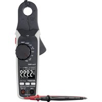
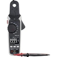
| Product type | Digital clamp meter |
| Brand | Voltcraft |
| Model | VC-524 |
| Display | Backlit LCD, 6000 counts |
| AC measurement method | True RMS |
| Measurement category | CAT III 600 V |
| Max. alternating current | 400 A (50-60 Hz) |
| Max. direct current | 400 A |
| Max. alternating voltage | 600 V (50-100 Hz) |
| Max. direct voltage | 600 V |
| Max. resistance | 60 MΩ |
| Max. capacitance | 6000 μF |
| Max. frequency | 10 kHz |
| Temperature | From -20 to +760 °C (type K probe) |
| Continuity test | Threshold < 50 Ω, audible tone |
| NCV detection | ≥ 230 V AC, distance ≤ 50 mm |
| Special functions | HOLD, REL, RANGE, LPF, Inrush, LED lamp |
| Power supply | 3 AAA/LR03 batteries 1.5 V |
| Auto power off | 15 minutes, can be disabled |
| Weight | Approx. 270 g |
| Jaw opening | Max. 32 mm |
| Included accessories | Test leads, type K temperature probe, batteries, manual |
Frequently Asked Questions - VC-524 VOLTCRAFT
User questions about VC-524 VOLTCRAFT
0 question about this device. Answer the ones you know or ask your own.
Ask a new question about this device
Download the instructions for your Multimeter in PDF format for free! Find your manual VC-524 - VOLTCRAFT and take your electronic device back in hand. On this page are published all the documents necessary for the use of your device. VC-524 by VOLTCRAFT.
USER MANUAL VC-524 VOLTCRAFT
GB Operating Instructions
Current clamp
Item No. 2754552 (VC-524 AC/DC)
Page 47 - 88
Operating Instructions
NL Operating Instructions
Stroomtang
Item No. 2754552 (VC-524 AC/DC) Pagina 133 - 177
UK CA CE
Inhaltsverzeichnis

text_image
QR code image containing encoded data, no visible human-readable texttext_image
VOLTCAFT distributed by Central Electric No. 50 Power Charge: 14 V DC330W-620Hz Model No: VCT-024 N M A WARMINGO TO AVOID ELECTRONAL SHOOT, BELOW TEXT LUXOR BANES CFLSHIA CABLE OR BATTERY COCUEL DO HOT CDFEATE WITH BATTERY COVER OP ELtext_image
CAT II (BOW) NOTtext_image
© AUTO 58.3%natural_image
Simple line drawing of an electric plug connected to a wall-mounted socket (no text or symbols)
natural_image
Simple line drawing of a plug with a lightning bolt and socket (no text or symbols)
text_image
3.278 000V L-066A 400A/TTMP 000V CAT V 200V TRUO RS15 Ramps V AC 0003 REVOCNVT VC-52% MOUNT 1.27 RESET MAX MAX COM 12+120 100.000V OUT RAMP IN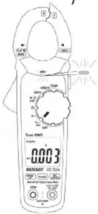
text_image
True AMS 0.003 POTSCM7 VC-524 MODEL: X1 MODEL: BCL MAX: 100 MAX: 100 MAX: 100 MAX: 100 MAX: 100 MAX: 100 MAX: 100 MAX: 100 MAX: 100 MAX: 100 MAX: 100 MAX: 100 MAX: 100 MAX: 100 MAX: 100 AX: 100 AX: 100 AX: 100 AX: 100 AX: 100 AX: 100 AX: 100 AX: 100 AX: 100 AX: 100 AX: 100 AX: 100 AX: 100 AX: 100 AX: N/A
text_image
MULTICRAFT Mitar CE A AAA AAA AAA A A A A A A A A A A A A A A A A
1 Introduction....49
2 Explanation of symbols....49
3 Intended use....50
4 Package contents ....52
5 Up-to-date operating instructions....52
6 Safety instructions ....53
7 Operating elements ....55
8 Product description....56
8.1 Rotary dial (F)....57
8.2 Display elements and symbols .....57
9 Taking measurements....60
9.1 Switching on the multimeter....60
9.2 Measuring current....61
9.3 Measuring voltage ("V") 64
9.4 Measuring frequency and pulse duration....66
9.5 Measuring the temperature....67
9.6 Measuring resistance ....69
9.7 Conducting a continuity test ....70
9.8 Diode test....71
9.9 Measuring capacitance....72
9.10 Non-contact AC voltage detection (NCV) 73
10 Additional functions....74
10.1 Automatic power-off....74
10.2 HOLD function 75
10.3 RANGE function .....75
10.4 REL function 75
10.5 LED light 76
10.6 LPF function (low-pass filter)....76
10.7 Inrush function....77
11 Cleaning and maintenance....78
11.1 General 78
11.2 Cleaning....78
11.3 Inserting/changing the batteries....79
12 Disposal....80
12.1 Product 80
12.2 (Rechargeable) batteries 81
13 Troubleshooting....82
14 Technical data....83
1 Introduction
Dear customer,
Thank you for purchasing this Voltcraft product.
Voltcraft produces high-quality measuring, charging and network devices that offer outstanding performance and innovation.
From the ambitious hobby enthusiast to the professional user, Voltcraft products provide the optimal solution for the most demanding tasks. Moreover, our reliable technology all comes at a very affordable price.
We are confident that your purchase of this Voltcraft product will be the beginning of a long, successful relationship.
We hope you enjoy your new Voltcraft product!
If there are any technical questions, please contact: www.conrad.com/contact
2 Explanation of symbols

The symbol with the exclamation mark in the triangle is used to highlight important information in these operating instructions. Always read this information carefully.
The triangle containing a lightning symbol indicates the risk of an electric shock or of the impairment of the electrical safety of the device.
The lightning symbol in the square permits current measurements on uninsulated, hazardous active conductors and warns of the possible hazards. Personal protective equipment must be used.
The arrow symbol indicates special information and advice on how to use the product.

This product has been CE-tested and meets the relevant European guidelines

Protection class 2 (double or reinforced insulation, protective insulation)
CAT I Measurement Category I: For measuring circuits of electrical and electronic equipment that is not directly supplied with a mains voltage (e.g. battery-operated devices, safety extra-low voltage systems, and signal/control voltages).
CAT II Measurement Category II: For measuring electrical and electronic devices that are directly supplied with a mains voltage via a mains plug. This category also includes all lower categories (e.g. CAT I for measuring signal and control voltages).
CAT III Measurement Category III: For measuring circuits of installations in buildings (e.g. mains sockets or sub-distributions). This category also includes all lower categories (e.g. CAT II for measuring electrical devices). Measuring in CAT III is only permitted with test prods with a maximum free contact length of 4 mm or with cover caps over the test prods.
Earth potential
3 Intended use
Measures and displays electrical parameters in measurement category CAT III (up to 600 V). Complies with the EN 61010-1 standard and all lower categories. The multimeter must not be used in the measuring category CAT IV.
■Measures alternating current up to max. 400 A (AC-TrueRMS)
Measures direct current up to max. 400 A
Measures DC and AC voltages up to 600 V (AC-TrueRMS)
Measures frequency up to 10 kHz
Measures temperature from -20 to +760 °C
Measures resistance up to 60 MΩ
Measures capacity up to 6000 μF
Continuity test (<50 Ω acoustic)
Diode test
Non-contact alternating voltage measurement (NCV) ≥230 V/AC and ≤50 mm gap
LPF (low-pass filter)
Inrush function
The measurement modes are selected using the rotary dial. The measuring range is selected automatically in many measurement modes and can also be set manually. Effective (True RMS) measurements are displayed when measuring AC voltages/currents.
Negative polarity readings are indicated with the (-) sign.
The current is measured via the current clamp. The circuit does not need to be opened to take a measurement. The current clamp can also be used to take measurements on uninsulated, hazardous conductors. The voltage in the measuring circuit must not exceed 600 V in CAT III. The use of personal protective equipment is recommended for CAT III measurements.
The multimeter is powered by three 1.5 V AAA batteries. Only use batteries of the specified type. Do not use 1.2 V rechargeable batteries. The multimeter switches off automatically to prevent the batteries from draining. The automatic power-off feature can be disabled.
Do not use the multimeter when the battery compartment is open or when the battery compartment cover is missing.
Do not take measurements in potentially explosive areas, damp rooms or adverse conditions. Adverse conditions include: Moisture or high humidity, dust and flammable gases, vapours or solvents, thunderstorms, and strong electromagnetic fields.
For safety reasons, only use test leads or accessories that match the multimeter's specifications.
The multimeter must only be used by people who are familiar with the relevant regulations and understand the potential hazards. The use of personal protective equipment is recommended.
This product is not intended to be used by people (including children) with impaired physical, sensory or mental capabilities or lack of experience and/or lack of knowledge. The use of measuring devices must be supervised by trained personnel.
Using this product for any purposes other than those described above may damage the product and result in a short circuit, fire or electric shock. The product must not be modified or reassembled!
Read the operating instructions carefully and keep them in a safe place for future reference.
Always observe the safety information in these instructions.
4 Package contents
Clamp multimeter
2x CAT III safety test leads
■Type-K temperature sensor (-20 to +250 °C)
Test leads to K-type thermocouple adaptor
3x 1.5 V AAA batteries
Safety information
Operating instructions
5 Up-to-date operating instructions
Download the latest operating instructions via the link www.conrad.com/downloads or scan the QR code. Follow the instructions on the website.
text_image
QR code image containing encoded data, no visible human-readable text6 Safety instructions

These instructions contain important information on how to use the multimeter correctly. Please read them carefully before using the multimeter for the first time.
Damage caused due to failure to observe these instructions will void the warranty. We shall not be liable for any consequential damage.
We shall not be liable for damage to property or personal injury caused by incorrect handling or failure to observe the safety information! Such cases will void the warranty/guarantee.
This device was shipped in a safe condition.
To ensure safe operation and avoid damaging the device, always observe the safety information and warnings in these instructions.
The unauthorized conversion and/or modification of the device is not permitted for safety and approval reasons.
Consult a technician if you are not sure how to use or connect the device, or if you suspect that the device is not safe to use.
Measuring instruments and their accessories are not toys and must be kept out of the reach of children.
Always comply with the accident prevention regulations for electrical equipment when using the product in commercial facilities.
In schools, educational facilities, hobby and DIY workshops, measuring devices must be operated under the responsible supervision of qualified personnel.
Before each measurement, make sure that the device is not set to a different measurement range.
When using test leads without protective caps, measurements between the multimeter and the earth potential must not exceed the CAT II measurement category.
When taking CAT III measurements, the cover caps must be placed on the probe tips to avoid accidental short circuits.

text_image
CAT I CAT II CAT IIIPush the cover caps onto the probe tips until they click into place. To remove the caps, pull them off the tips with some force.
Always remove the test probes from the measured object before changing the measurement range.
The voltage between the multimeter connection points and earth must never exceed 600 V in CAT III.
Exercise particular caution when working with voltages higher than 33 V (AC) and 70 V (DC). Touching electrical conductors with these voltages may cause a fatal electric shock.
To prevent an electric shock, do not touch the measuring points when taking measurements, either directly or indirectly. When taking measurements, do not touch any area beyond the grip markings on the test probes and the multimeter.
Check the multimeter and test leads for signs of damage before each measurement. Never take measurements if the protective insulation is damaged (torn, missing, etc.). The test leads come with a wear indicator. A second layer of insulation will become visible if the lead is damaged (the second layer of insulation is a different colour). If this occurs, discontinue use and replace the measurement accessory.
Do not use the multimeter immediately prior to, during or just after a storm (risk of electric shock / power surge). Ensure that your hands, shoes, clothes, the floor, circuit and circuit components are dry.
Avoid using the device in the immediate vicinity of:
– Strong magnetic or electromagnetic fields
- Transmitting antennas or HF generators.
These may distort the measurements.
If you suspect that safe operation is no longer possible, discontinue use immediately and prevent unauthorized use. Safe operation can no longer be assumed if:
– There are signs of damage
– The device does not function properly
- The device was stored under unfavourable conditions for a long period of time
– The device was subjected to rough handling during transport
Do not switch the device on immediately after it has been brought from a cold room into a warm one. The condensation generated may destroy the product. Leave the device switched off and allow it to reach room temperature.
Do not leave packaging material lying around carelessly, as it may become a dangerous toy for children.
Observe the safety information in each section.
7 Operating elements
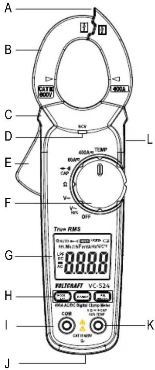
text_image
A B CATB 600V 400A C D L E F 400A TEMP 60A CAP Ω V~ V~ Hrx OFF True RMS AUTO ← INRUSH REL MHz 2.5 FmVA Hz/VC* LPF 8.0.0.0 DC = AC VOLTCAFT VC-524 MODE LPE RANGE REL INRUSH 490A AC/DC Digital Clamp Meter COM VZ → CAP H/S TEMP CAT IS MOV K I J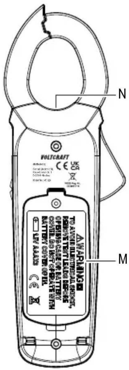
text_image
VOLTCAFT distributed by: Central Electric Co. SE Radar/Control Unit 1 DC2000-05-26 Model No: VCT-328 N M AWARMING TO ANGE ELECTRICAL CHECK, FORCATE TEXT LEAL OR RESO OPEN CARE OF BATTERY OFFICE RED OUT OPERATE WITH BATTERY COVER OPTIL UV ALABS N CAA Cable separator with integrated NCV sensor
B Current clamp
C Grip markings
D NCV signal display
E Current clamp opening lever
F Rotary dial for selecting the measurement mode
G Display
HFunctionbuttons
MODE button for switching functions
LPF button to enable the low-pass filter in V-AC mode
RANGE button for manually selecting the range
REL button for relative measurements
INRUSH button for inrush function
I COM measurement terminal (reference potential, "negative")
J Multifunction thread (1/4" UNC, tripod socket) for optional accessories
K VΩ measurement terminal (“positive potential” for direct voltages)
L HOLD function button for holding the measured value and for the LED light
M Battery compartment
N LED light
8 Product description
The digital multimeter (DMM) displays measurements on a backlit digital display. The DMM has a 6000-count display (count = smallest display value). The display can display values from 0 to 5999.
The VC-524 is designed to measure direct and alternating current of up to 400 A.
The multimeter switches off automatically after a period of inactivity. This protects the batteries and extends the battery life. The automatic power-off feature can be disabled.
The DMM can be used to take measurements up to CAT III. It is suitable for use in hobby workshops and professional applications.
Protective caps may be attached to the angled test lead plugs. Remove these before inserting the test leads into the multimeter.
8.1 Rotary dial (F)
The measurement modes are selected using the rotary dial. Automatic range selection (“AUTO”) is enabled in some measurement modes. This sets the measurement range automatically.
To turn the multimeter off, move the control dial to the "OFF" position. Always turn the multimeter off when it is not in use.
8.2 Display elements and symbols
text_image
1 2 3 4 5 6 7 AUTO → HOLD INRUSH REL MkΩ F m VA Hz% °C°F LPF 8.0.0.0 DC AC 11The following symbols and letters appear on the device/display.
| Description | |
| 1 Automatic power-off is enabled | |
| 2 Automatic range selection is enabled | |
| 3 Diode test symbol | |
| 4 Continuity test symbol | |
| 5 Symbol for active data hold function | |
| 6 INRUSH symbol | |
| 7 Battery status indicator | |
| 8 Symbol for measuring frequency and pulse duration ratio in % | |
| 9 Temperature unit (°Celsius = European, °Fahrenheit = empirical) | |
| 10 | V = Volt (unit of electrical voltage), mV = Millivolt (exp.-3)A = Ampere (unit of electric current) |
| 11 Measured value | |
| 12 Alternating current symbol | |
| 13 Prefix for negative readings | |
| 14 Direct current symbol | |
| 15 Low-pass filter symbol | |
| 16 | nF = Nanofarad (exp.-9, unit of electrical capacity)= μF Microfarad (exp.-6) |
| 17 Active relative value measurement | |
| 18 | Ω = Ohm (unit of electrical resistance)kΩ = Kilo-Ohm (exp.3)MΩ = Mega-Ohm (exp.6) |
| LPF Low-pass filter for AC current measurement | |
| INRUSH Start-up current measurement for AC measuring range | |
| OFF Move to this position to turn the multimeter off | |
| NCV Contactless AC voltage detection (V-AC only) | |
| True RMS | Actual effective value |
| HOLD Enable/disable data hold function | |
| REL | Make a relative measurement and set the reference value (not possible for continuity tests, diode tests, frequency and NCV measurements) |
| RANGE Use this button to manually select the measurement range | |
| MODE Use this button to switch between different measurement functions | |
| OL Overload indicator; the measuring range was exceeded | |
 | Battery data symbol |
 | Diode test function |
 | Acoustic continuity test |
 AC Alternating current symbol AC Alternating current symbol | |
 DC Direct current symbol DC Direct current symbol | |
| COM Connection for reference potential | |
| V Voltage mode (Volt = unit of electrical voltage) | |
| A Current mode (Ampere = unit of electric current) | |
| Hz% Frequency mode (Hertz = unit of frequency) and pulse duration ratio | |
| Ω Resistance mode (Ohm = unit of electrical resistance) | |
| CAP Capacity measurement function | |
| TEMP Temperature measurement function | |
 | Position marker for the conductor to ensure the correct current measurement. |
 | Button for switching the measurement light on and off |
9 Taking measurements

Never exceed the maximum permitted input values. Never touch circuits or parts of circuits when they may contain voltages greater than 33 V/ACrms or 70 V/DC! Fatal hazard!
Before measuring, check the connected test leads for damage, such as cuts, tears and kinks. Never use damaged test leads, as this may cause a fatal electric shock!
Before working with the multimeter, check that the measuring function is working correctly. Always start by taking a measurement on a known source and monitor the display carefully. A faulty multimeter may present a fatal hazard for the user. In the event of a fault, inspect the multimeter and consult a technician if necessary.
When taking measurements, do not touch any area beyond the grip markings on the test probes and the multimeter.
Only connect the two test leads that you require to take measurements. For safety reasons, remove all unnecessary test leads from the device before taking a measurement.
Measurements in circuits rated at >33 V/AC and >70 V/DC must only be made by qualified and trained personnel who are familiar with the relevant regulations and the associated hazards.
“OL” (overload) indicates that the measuring range has been exceeded.
9.1 Switching on the multimeter
The multimeter is turned on and off via the rotary dial. Turn the rotary control (F) to select the desired mode. To turn the multimeter off, move the control dial to the "OFF" position. Always turn the multimeter off when it is not in use.
The multimeter conducts a short function test after it is switched on. During the function test, all symbols will appear on the display.

Insert the batteries before using the multimeter. For more information on inserting/replacing the batteries, see “Cleaning and maintenance”.
9.2 Measuring current

Never exceed the maximum permitted input values. Never touch circuits or parts of circuits when they may contain voltages greater than 33 V/ACrms or 70 V/DC! Fatal hazard!
Do not measure current on a circuit with a voltage of more than 600 V in CAT III.
Pay attention to the necessary safety information, regulations and protective measures for your own safety.
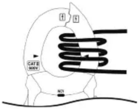
The current is measured via the current clamp (B). The sensors in the current clamp detect the magnetic field created by current-carrying conductors. You can take measurements on insulated and uninsulated conductors. Ensure that the conductor always passes through the centre of the current clamp (pay attention to the arrow marks) and that the clamp is always closed.
A cable separator (A) is located on the tip of the pliers, which allows you to separate tangled cables. This makes it easier to separate the desired cable.
Do not use the current clamp to surround more than one conductor. If the supply and return conductors (e.g. L and N) are measured, the currents will cancel each other out and no measurement will be displayed. If several supply conductors (e.g. L1 and L2) are measured, the currents will be added together.
At low currents, the conductor can be wound around one side of the current clamp to increase the total measured current. Divide the measured current by the number of coils. You will then receive the correct current value.
text_image
CAT II 900V NOTFollow the steps below to measure AC (A) currents:
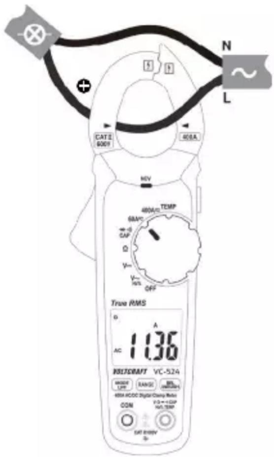
Switch on the DMM using the rotary dial (F) and select the “A” measurement mode and the predicted measurement range (60 A / 400 A). “A” and the AC symbol AC will appear on the display.
The display is automatically set to zero when the current clamp is closed. If there is a strong magnetic field that affects the reading, use the relative value function ("REL").
Press the opening lever (E) to open the current clamp.
Surround the conductor that you want to measure and close the current clamp. Position the conductor in the middle between the two triangular position symbols on the clamp.
The measured current is indicated on the display.
After taking a measurement, remove the current clamp from the measured object and switch off the DMM. Turn the rotary switch to the "OFF" position.
text_image
CAT II 6009 400A N L HEV 400A/10 TEMP 60A/2C CAP D Y Y INT OFF True RMS D A AC 1.136 INSFRAFT VC-524 MANNER LFP RANGE BILS (NOMINALS) 400A HCCDC Digital Clamp Ratio COM F:0+++CAP N/A.TEMP CAT B:800V SFollow the steps below to measure DC (A) currents:
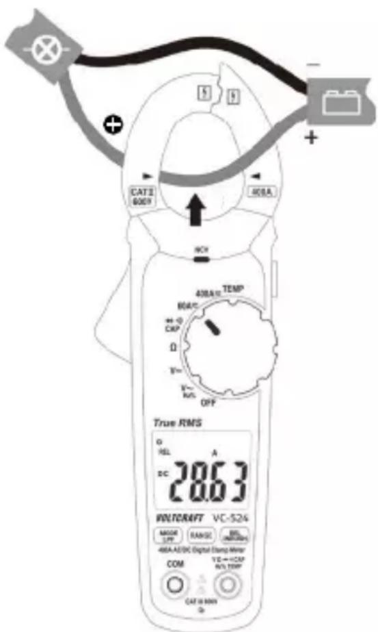
Switch on the DMM using the rotary dial (F) and select the "A measurement mode and the predicted measurement range (60 A / 400 A). "A" and the AC symbol AC will appear on the display.
Press the "MODE" button to switch to DC mode. "DC" will appear on the display.
The display is automatically set to zero when the current clamp is closed. If there is a strong magnetic field that affects the reading, use the relative value function ("REL").
Press the opening lever (E) to open the current clamp.
Surround the conductor that you want to measure and close the current clamp. Position the conductor in the middle between the two triangular position symbols
on the clamp. Pay attention to the direction of the current. The positive wire must run from front to back from the current source.
text_image
CATS 6009 40BA TEMP MOUT + -0 CKP Ω T=1 R=1 K/S OFF True RMS O REL A DC 28.63 WOLTCRAFT VC-524 MODE LWP RANGE BI (NOTATO) 48A-AE/DC Digital Clamp Meter COM VE→CCP N/A TWP CAT 10 MIN QThe measured current is indicated on the display.
If a negative current is displayed, this indicates that the polarity of the wire is reversed or the current is flowing in the opposite direction (e.g. solar powered or charging devices).
After taking a measurement, remove the current clamp from the measured object and switch off the DMM. Turn the rotary switch to the "OFF" position.
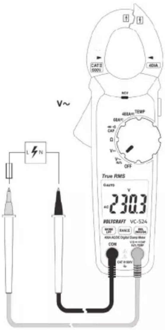
9.3 Measuring voltage ("V")
Follow the steps below to measure AC (V) voltages:
Turn the multimeter on and select "V \~" mode.
Plug the red lead into the V terminal (K) and the black lead into the COM terminal (I).
Connect both of the test leads to the measured object (e.g. generator or mains voltage) in parallel.
The "V DC/AC" voltage range has an input resistance of ≥ 10 MOhm.
After measuring, remove the test leads from the measured object and turn the multimeter off.
text_image
CATII 000V 400A NCV L N V~ 400A TEMP 60A CAP Ω V~ V- RMS OFF True RMS GAUTO 230.3 AC WILTSRAFT VC-524 MODE LFP RANGE BIL INRUSH 40A/ACDC Digital Clamp Motor COM V3 = +5MP N/A TEMF CAT II-50VFollow the steps below to measure DC (V) voltages:
Turn the DMM on and select "V---" mode.
Plug the red lead into the V terminal (K) and the black lead into the COM terminal (I).
Connect both of the test prods to the measured object (battery, circuit etc.) in parallel. Connect the red measuring probe to the positive terminal and the black measuring probe to the negative terminal.
The measured value is displayed together with the polarity.
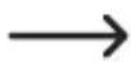
If “-” appears in front of a direct voltage measurement, this indicates that the measured voltage is negative (or that the measuring probes have been connected in reverse).
The "V DC/AC" voltage range has an input resistance of ≥ 10 MOhm.
text_image
CAT II 600V 400A RCY 400A TEMP 90V CAP Ω V- OFF True RMS Ω AUTO V 13.80 WNTCRAFT VC-524 MOOR DP RANGE REL INRDC 600A ACDC Digital Clamp Resistor COM V D → +CAP HV TEMP CAT II 600V ΦAfter measuring, remove the test leads from the measured object and turn the multimeter off.
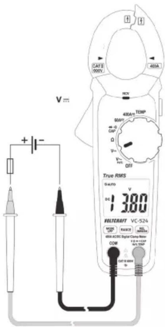
9.4 Measuring frequency and pulse duration
The multimeter can be used to measure the frequency of a signal voltage (supports frequencies from 5 Hz to 10 kHz). Observe the input specifications in the technical data.
Proceed as follows to take a frequency measurement:
Switch on the DMM and select "Hz" mode. "V\~" will appear on the display.
Press the "MODE" button once. "Hz" will appear on the display.
Plug the red lead into the Hz terminal (K) and the black lead into the COM terminal (I).
Connect the two measuring probes to the object that you want to measure (e.g. signal generator or circuit).
The frequency will be displayed together with the corresponding unit..
After measuring, remove the test leads from the measured object and turn the multimeter off.
text_image
Hz CAT 8 600V 400A HCV 400A/400V TEMP 80V/2 CAP Q V- K- M/S OFF True RMS 6 micro 3 Hz 50.00 MULTICRAFT VC-524 MODE LFP RANGE MAX NMAX 400A AC/DC Digital Clamp Meter COM I D = I CAP 95% TEMP CAT 8 600VMeasuring the pulse duration in %
The DMM can display the pulse duration of an AC voltage signal's positive half wave as a percentage of the entire period.
Follow the steps below to measure the pulse duration in %:
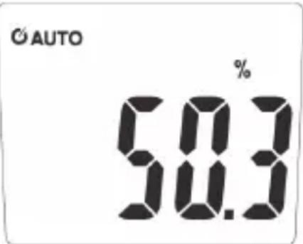
Turn the DMM on and select the “%” measurement mode. “V” will appear on the display.
Press the "MODE" button twice. "%" will appear on the display.
Plug the red lead into the Hz terminal (K) and the black lead into the COM terminal (I).
Connect the two measuring probes to the object that you want to measure (e.g. signal generator or circuit).
The pulse duration of the positive half wave is shown as a percentage value on the display. For a symmetrical signal, the pulse duration will be displayed as 50%.
After taking a measurement, remove the leads from the measured object and switch off the DMM.
text_image
© AUTO % 58.39.5 Measuring the temperature

When taking a temperature measurement, only allow the temperature probe to come into contact with the surface of the measured object. The multimeter must not be exposed to temperatures below or in excess of the operating temperature, as this may lead to incorrect measurements.
The temperature probe must only be used on voltage-free surfaces.
The included type-K thermal sensor can measure temperatures from -20 to +250 °C.
To measure the full temperature range supported by this product (-20 to +760 °C) you must purchase a sensor with a greater measurement range.
The included type-K sensor adaptor supports a miniature plug.
All K-type thermal sensors can be used for taking temperature measurements.
The temperature can be displayed in °C or °F.
Follow the steps below to measure the temperature:
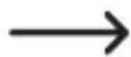
Turn on the DMM and select the "TEMP" measurement mode. "°C" will appear on the display.
Use the "MODE" to change the temperature unit.
Insert the temperature probe into the temperature measuring adapter in the correct polarity. The thermocouple plug can only be inserted into the measurement adapter in the correct polarity. Do not use force when inserting the plug.
Insert the positive terminal on the measurement adapter into the temperature measurement socket (K) and the negative terminal into the COM measurement socket (I).
The temperature will appear on the display.
“OL” indicates that the measurement range was exceeded or the sensor was disconnected.
After measuring, remove the sensor and turn off the multimeter.
If no temperature sensor is connected, the ambient temperature of the DMM can be displayed using a jumper between the two measurement sockets ("COM" and "Temp"). As the sensor is located inside the housing, the display reacts very slowly to temperature fluctuations. This function helps you check that the DMM is at the correct operating temperature after storage. An external sensor must be used for quick measurements.
text_image
CAT II 400V 400A HCV TEMP °C°F 400A 60A CAP Ω V~ V~ HE% OFF True RMS 2 18.5 °C VOLTCAFT VC-524 MUSIC L/FF FLANDS SEL 30000000000 400A ACDC Digital Clamp Meter COM VD++eCAP ROLTTEMP CAT B/WUV9.6 Measuring resistance

Make sure that all objects that you wish to measure (including circuit components, circuits and component parts) are disconnected and discharged.
Follow the steps below to measure the resistance:
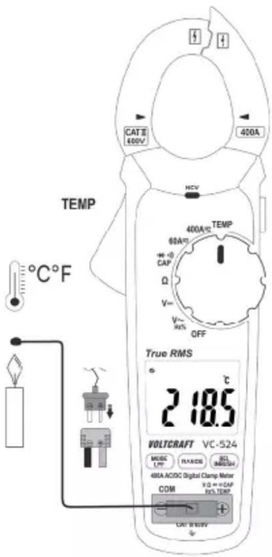
Turn on the DMM and select the “Ω” measurement mode.
Plug the red lead into the terminal (K) and the black lead into the COM terminal (I).
Check the measuring leads for continuity by connecting both measuring probes to one another. The multimeter should show a resistance value of approx 0 - 0.5 Ω (inherent resistance of the test leads).
For low-impedance measurements (<400 Ohm), press the “REL” button to discount the inherent impedance of the test leads in the subsequent resistance measurement. “REL” will appear on the display and the main display will show 0 Ohm. Automatic range selection (AUTO) is now disabled. For all other measurements, the inherent resistance of the test leads is negligible. Press the “REL” button again to disable the reference value function. Automatic range selection is now enabled.
text_image
S H CATE 100V 400A MCV 400mA TEMP 60kPa DC D 50 F R OFF True RMS 10.05 PHLISRAFT VC-524 RANGE LEFT RANGE MAXIMUM GND/CCDC Digital CMay Meter VZ + OFF MAX.100V CDS DC 100V ΩConnect the measuring probes to the object that you want to measure. The measurement will be indicated on the display (provided that the object you are measuring is not highly resistive or disconnected). Wait until the display stabilises. This may take a few seconds for resistances greater than 1 MΩ.
“OL” (overload) indicates that the measuring range has been exceeded or that the circuit is broken.
After taking a measurement, remove the leads from the measured object and switch off the DMM.
When taking a resistance measurement, make sure that the points that come into contact with the measuring prods are free from dirt, oil, solder and other impurities. These substances may distort the measurement.
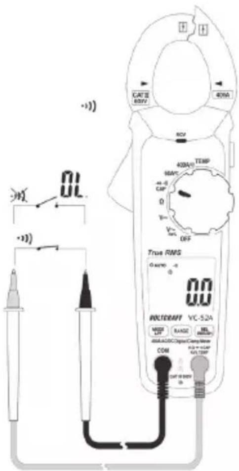
9.7 Conducting a continuity test

Make sure that all objects that you wish to measure (including circuit components, circuits and component parts) are disconnected and discharged.
Switch on the DMM and select the mode. The continuity test symbol and the symbol will appear on the display. Press the button again to switch to the next measuring mode.
Plug the red lead into the V terminal (K) and the black lead into the COM terminal (I).
An approximate value of <50 Ohm is recognized and you will hear a beep. The continuity test measures resistances of up to 400 Ohm.
"OL" (overload) indicates that the measuring range has been exceeded or that the circuit is broken.
After taking a measurement, remove the leads from the measured object and switch off the DMM.
text_image
CATII 80kV 40mA 80V 400A/1 TEMP 60kV -44.0 CAP 0 V- OFF True RMS 0 amper -0 0.0 POLT/DAFT VC-52A MOSI LUT BANG 100Ω dVA-A/DC Digital Comp Meter COM 0.0 + 1.0kV VAI TEMF DIF = 100kV 0.09.8 Diode test

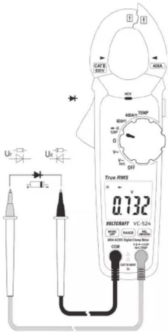
Make sure that all objects that you wish to measure (including circuit components, circuits and component parts) are disconnected and discharged.
Switch on the DMM and select the → mode. Press the “MODE” button to switch measurement modes. The diode test symbol and the V unit will appear on the display. Press the button again to switch to the next measuring mode.
Plug the red lead into the V terminal (K) and the black lead into the COM terminal (I).
Check the measuring leads for continuity by connecting both measuring probes to one another. A value of approx. 0.000 V should be shown.
Connect the measuring probes to the object that you want to measure (diode).
The continuity voltage ("UF") will be shown in Volts (V). "OL" indicates that the diode is reverse-biased or defective. Try taking the measurement again in the opposite polarity.
After taking a measurement, remove the leads from the measured object and switch off the DMM.
text_image
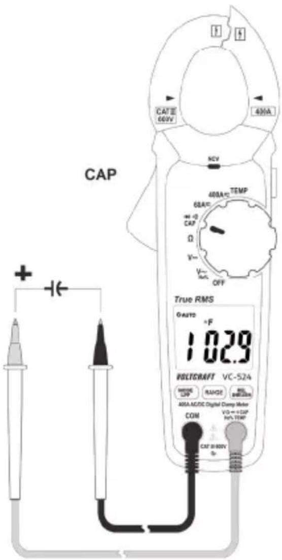
CAT 8 900V 408A MCV 400A TEMP 90W CAP Ω V+ V- RES OFF True RMS 0.732 WALTCAFF VC-524 MOSS UP RANGE REL INFLUOR 408A ACDC Digital Clamp Meter COM E D → +CAP HV-TEMP CAT 10 600V9.9 Measuring capacitance

Make sure that all objects that you wish to measure (including circuit components, circuits and component parts) are disconnected and discharged. Always pay attention to the polarity when using electrolytic capacitors.
Turn the DMM on and select "CAP" mode.
Press the "MODE" button twice to change the measurement mode. "nF" will appear on the display. Press the button again to switch to the next measuring mode.
Plug the red lead into the V terminal (K) and the black lead into the COM terminal (I).
Due to the sensitive measuring input, the display may show a small reading even with "open" test leads. Press the "REL" button to reset the display to "0". The REL function should only be used for small capacitances.
Connect the two test probes (red = positive, black = negative) to the object that you want to measure (condenser). The capacitance will be shown on the
text_image
CAP CAIT面 60V 40mA NCV 400A/2 TEMP 60A/ +/-0 CAP Ω V~ V~ OFF True RMS GASYS +F 1.029 BOLTGRAFT VC-S24 MOSO LDP RANGE RIL BHLOOM 40A-AC/DC Digital Clamp Meter COM V3=+CAP No-TEMP CAT 8-80V +display after a few seconds. Wait until the display stabilises. This may take a few seconds for capacitances greater than 40 F .
- “OL” (overload) indicates that the measuring range has been exceeded.
- After taking a measurement, remove the leads from the measured object and switch off the DMM.
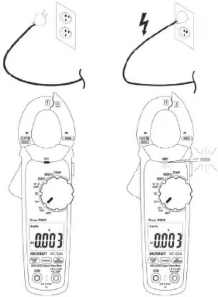
9.10 Non-contact AC voltage detection (NCV)

The voltage detector is only designed for quick tests and by no means replaces a contact bipolar voltage test. This function must not be used to check that no voltage is present before carrying out work.
The NCV function (non-contact voltage detection) enables the contactless detection of an AC voltage on electrical conductors. The NCV sensor (A) is located on the top of the current clamp.
Switch the DMM on. The "NCV" function is activated as soon as the DMM is switched on.
Place the NCV sensor as close as possible to an electrical conductor.
If an AC voltage is detected, the red NCV LED (D) will turn on.
The highly sensitive NCV sensor may cause the diode to glow when static electricity is present. This is normal and does not indicate that the multimeter is faulty.
text_image
DCAT 28 (500V) 1.400A 300 450A/500V 50kV 60kV 70kV 80kV 90kV 100kV 110kV 120kV 130kV 140kV 150kV 160kV 170kV 180kV 190kV 200kV 210kV 220kV 230kV 240kV 250kV 260kV 270kV 280kV 290kV 300kV 310kV 320kV 330kV 340kV 350kV 360kV 370kV 380kV 390kV 400kV 410kV 420kV 430kV 440kV 450kV 460kV 470kV 480kV 490kV 500kV 510kV 520kV 530kV 540kV 550kV 560kV 570kV 580kV 590kV 600kV 610kV 620kV 630kV 640kV 650kV 660kV 670kV 680kV 690kV 700kV 710kV 720kV 730kV 740kV 750kV 760kV 770kV 780kV 790kV 800kV 810kV 820kV 830kV 840kV 850kV 860kV 870kV 880kV 890kV 900kV 910kV 920kV 930kV 940kV 950kV 960kV 970kV 980kV 990kV 1000A
Always test the NCV
function first on a known AC voltage source to avoid incorrect measurements. Incorrect measurements may cause an electric shock. The inner conductors are twisted in many cables. For this reason, move the sensor a few centimetres along the cable to ensure that you cover all parts of the inner conductors.
10 Additional functions
The multimeter comes with the following additional functions that you can use when taking measurements.
10.1 Automatic power-off
The multimeter switches off automatically after 15 minutes if no buttons are pressed and the rotary dial is not moved. This protects the batteries and prolongs the battery life.
The multimeter will beep five times approximately one minute before switching off. Press any button to keep the multimeter switched on for a further 15 minutes.
If no buttons are pressed, the multimeter will emit a long beep tone and switch off.
If the multimeter switched off automatically, press any button to switch it back on. Alternatively, move the rotary dial over the “OFF” position. The multimeter will switch back on after 1 - 2 seconds.
The “💡symbol indicates that automatic power-off is enabled.
Disabling automatic power-off
When taking prolonged measurements, it is necessary to disable the automatic power-off feature. To disable this feature, switch off the multimeter.
Hold down the “MODE” button and switch on the DMM using the rotary dial. The multimeter will beep three times and the automatic power-off symbol will no longer appear on the display.
The multimeter will stay switched on until you switch it off or the batteries are exhausted. Automatic power-off is automatically re-enabled when you switch off the multimeter.
10.2 HOLD function
This feature freezes the current reading on the display so that you can record it for future reference.

When testing live wires, make sure that this function is disabled before taking any measurements, otherwise the measurement will be incorrect!
Press the "HOLD" button (L) on the side of the multimeter to enable this feature. The multimeter will beep and "HOLD" will be displayed.
To disable the hold feature, press the "HOLD" button or change the measuring mode.
10.3 RANGE function
The RANGE button allows you to switch from automatic range selection (AUTO) to manual range selection. This is necessary if the wrong range is selected or the multimeter keeps switching between two ranges.
Press the “RANGE” button to select the next measuring range (if the highest measuring range is selected, the multimeter will go back to the lowest range).
To disable manual range selection, hold down the “RANGE” button for approximately one second. This will re-enable automatic range selection. Manual range selection is enabled when “AUTO” is not displayed.
10.4 REL function
The REL function allows you to take a reference measurement to avoid possible line losses (e.g. during resistance measurements). This function resets the current measurement to zero.
Press the “REL” button to enable this mode and save the reference value. “REL” will appear on the display. The display will be reset to zero and automatic range selection will be disabled.
To disable this mode, press the "REL" button again or change the measuring mode using the rotary dial.

The REL function is not available in the following modes: Continuity test, diode test, frequency and pulse ratio.
10.5 LED light
When the DMM is switched on, the side-mounted light button (L) can be used to switch the LED light on and off. Hold down the button for approximately 2 seconds to switch the light on/off. The light will stay switched on until it is switched off using the light button (L), or until the multimeter is switched off with the rotary dial ("OFF" position) or the automatic power-off feature.
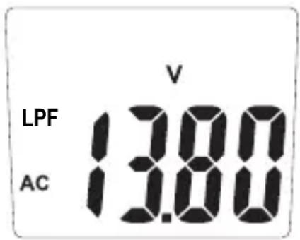
10.6 LPF function (low-pass filter)
The LPF function permits suppression of undesired measured signals above 160 Hz in the measuring function V-AC. The signals are weakened by approx. -24 dB/octave.
Push and hold (2 s) the button "LPF". Input is confirmed by a beep. The display shows the symbol "LPF" together with the current type "AC".
Connect the current probe to the object to be measured.
The measured value is indicated on the display.
Push and hold (2 s) the button "LPF" to return to the normal measuring function.

text_image
LPF AC V 13.80The LPF function is only available in AC voltage measuring operation.
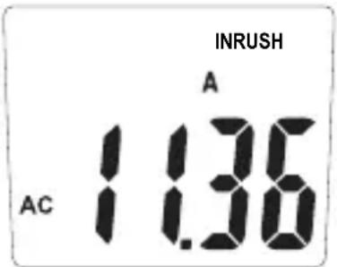
10.7 Inrush function
The inrush function permits recording of start-up currents within 100 ms (milliseconds) in the measuring function A-AC. The measurement takes place in the measuring range of 300 A with a trigger current of 5 A.
Keep the button "INRUSH" pressed for approx. 2 seconds. Input is confirmed by a beep.
- The display shows the symbol "INRUSH" together with the current type "AC".
– Four dashes indicate readiness for measuring.
Connect the current probe to the object to be measured.
Switch on the object to be measured. Once the trig-
ger current of 5 A has been exceeded, the start-up current will be displayed. The measured value remains on the display.
Push and hold (2 s) the button "Inrush" to return to the normal measuring function.
text_image
INRUSH A 1.36 AC
The inrush function is only available in AC current measuring operation.
The hold function is not available when the inrush function is active.
11 Cleaning and maintenance
11.1 General
The multimeter should be calibrated once a year to ensure that measurements remain accurate.
The multimeter does not need to be serviced (apart from occasional cleaning and replacing the battery).
Refer to the following sections for instructions on how to change the battery.

Regularly check the device and test leads for signs of damage.
11.2 Cleaning
Always observe the following safety information before cleaning the device:

Opening covers on the product or removing parts that cannot be removed by hand may expose voltage-carrying components.
Before
cleaning or servicing the multimeter, disconnect all cables from the multimeter and all measured objects. Switch off the multi-meter.
Do not use abrasive detergents, petrol, alcohol or other similar chemicals to clean the device. These may corrode the surface of the multimeter. In addition, the vapours emitted by these substances are explosive and harmful to your health. Do not use sharp-edged tools, screwdrivers or metal brushes to clean the device.
Use a clean, damp, lint-free and antistatic cloth to clean the multimeter, display and test leads. Allow the multimeter to dry out completely before using it again.
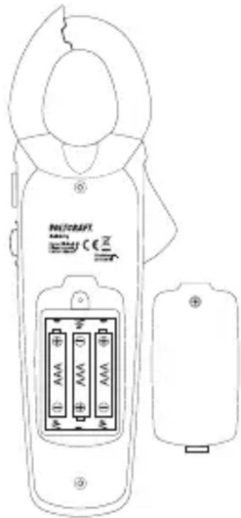
11.3 Inserting/changing the batteries
The multimeter is powered by three 1.5 V AAA batteries. Insert three new batteries before using the multimeter for the first time or when the low battery symbol ( ) is displayed.
Proceed as follows to insert/replace the battery:
- Disconnect the connected measuring leads from the measuring circuit and from the multimeter. Disconnect the multimeter from all measured objects. Switch off the multimeter.
Remove the rear screw on the battery compartment cover (M) using a suitable Phillips screwdriver. The screw cannot be completely removed. Remove the battery compartment cover.
Replace all used batteries with new ones of the same type. Insert the new batteries into the battery compartment in the correct polarity. Refer to the polarity markings in the battery compartment.
Carefully replace the battery compartment cover.
text_image
NUTRAFT CE IN ① AAA +D ② AAA +D ③ AAA +D
Never use the multimeter when it is open. FATAL HAZARD!
leave empty batteries in the device. Even leakproof batteries may corrode and destroy the device or release chemicals that are detrimental to your health.
Do not leave batteries unattended. They may be swallowed by children or pets. Seek immediate medical attention if a battery is swallowed.
If you do not plan to use the multimeter for an extended period, remove the battery to prevent it from leaking.
Leaking or damaged batteries may cause acid burns if they come into contact with your skin. Always use protective gloves when handling leaking or damaged batteries.
Batteries must not be short-circuited or thrown into open flames!
Do not recharge or disassemble non-rechargeable batteries. This may cause a fire or explosion.
Only use alkaline batteries, as alkaline batteries are more powerful and have a longer lifespan.
12 Disposal
12.1 Product
This symbol must appear on any electrical and electronic equipment placed on the EU market. This symbol indicates that this device should not be disposed of as unsorted municipal waste at the end of its service life.
Owners of WEEE (Waste from Electrical and Electronic Equipment) shall dispose of it separately from unsorted municipal waste. Spent batteries and accumulators, which are not enclosed by the WEEE, as well as lamps that can be removed from the WEEE in a non-destructive manner, must be removed by end users from the WEEE in a non-destructive manner before it is handed over to a collection point.
Distributors of electrical and electronic equipment are legally obliged to provide free take-back of waste. Conrad provides the following return options free of charge (more details on our website):
in our Conrad offices
at the Conrad collection points
at the collection points of public waste management authorities or the collection points set up by manufacturers or distributors within the meaning of the ElektroG
End users are responsible for deleting personal data from the WEEE to be disposed of.
It should be noted that different obligations about the return or recycling of WEEE may apply in countries outside of Germany.
12.2 (Rechargeable) batteries
Remove batteries/rechargeable batteries, if any, and dispose of them separately from the product. According to the Battery Directive, end users are legally obliged to return all spent batteries/rechargeable batteries; they must not be disposed of in the normal household waste.
Batteries/rechargeable batteries containing hazardous substances are labelled with this symbol to indicate that disposal in household waste is forbidden. The abbreviations for heavy metals in batteries are: Cd = Cadmium, Hg = Mercury, Pb = Lead (name on (rechargeable) batteries, e.g. below the trash icon on the left).
Used (rechargeable) batteries can be returned to collection points in your municipality, our stores or wherever (rechargeable) batteries are sold. You thus fulfil your statutory obligations and contribute to environmental protection.
Batteries/rechargeable batteries that are disposed of should be protected against short circuit and their exposed terminals should be covered completely with insulating tape before disposal. Even empty batteries/rechargeable batteries can contain residual energy that may cause them to swell, burst, catch fire or explode in the event of a short circuit.
13 Troubleshooting
The multimeter was designed using the latest technology and is safe to use.
However, problems and malfunctions may still occur.
This section tells you how to troubleshoot common issues:

Always observe the safety information in these instructions.
| Error Possible cause Solution | ||
| The multimeter does not function | Are the batteries empty? | Check the status. Replace the bat-teries. |
| The measured value does not change. | Have you selected the wrong measurement mode (AC/DC)? | Check the display (AC/DC) and select another mode if necessary. |
| Are the measuring leads plugged into the measuring sockets correctly? | Check that the measuring leads are in the correct position. | |
| Is the hold function enabled ("HOLD")? | Press the "HOLD" button to disable this function. | |

Any repair work other than that described above must be carried out by an authorized technician. If you have questions about the multimeter, please contact our technical support team.
14 Technical data
Display......6000 Counts (digits)
Sample rate ....Approx. 3 readings/second
Measurement method V/AC, A/AC .... True RMS (real effective value measurement)
Test lead length ....Approx. 90 cm
Measuring impedance ....>10 MΩ (V range)
Current clamp opening ......Max. 32 mm
Measurement socket spacing....19 mm
Automatic power-off....After 15 minutes (can be disabled)
Power supply....3x 1.5 V AAA batteries
Current consumption .... Nominal approx. 30 mA, max. 70 mA (continuity test/LED light)
Standby (automatic power-off)
Approx. 5 μA
Operating conditions.... +5 to +31 °C (<80% RH)
+31 to +40 °C (80% RH declining in a linear fashion to <50% RH)
Operating altitude ......Max. 2000 m
Storage conditions....-20 °C to +60 °C, max. 80% RH
Weight ....Approx. 270 g
Dimensions (L x W x H)....209 x 70 x 35 mm
Measuring category....CAT III 600 V
Pollution degree....2
Safety accordint to....EN61010-1, EN61010-2-032, EN61010-2-033
Measuring tolerances
Accuracy in ± (% of reading + display error in counts (= number of smallest points)). These accuracy readings are valid for one year at a temperature of +23 °C (± 5 °C) and a relative humidity of less than 75% (non-condensing). Temperature coefficient: +0.1x (specified accuracy)/1 °C
The accuracy of measurements may be affected when the multimeter is used in a high-frequency electromagnetic field.
Alternating current
| Range Resolution Accuracy* | |
| 60.00 A 0.01 A ±(2% + 17) | |
| 400.0 A 0.1 A ±(2.8% + 8) | |
| Frequency range: 50 - 60 Hz; Overload protection: 600 V, 400 A*Measuring position error: Accuracy deviation for non-centred measurement position: ±1% | |
| TrueRMS crest factor (CF) for non-sinusoidal signals: max. 3.0CF >1.4 - 2.0 + 1%CF >2.0 - 2.5 + 2.5%CF >2.5 - 3.0 + 4% | |
Direct current
| Range Resolution Accuracy* | ||
| 60.00 A 0.01 A ±(2.8% + 12) | ||
| 400.0 A 0.1 A ±(2.8% + 8) | ||
| Overload protection 600 V, 400 A*Measuring position error: Accuracy deviation for non-centred measurement position: ±1% | ||
AC voltage
| Range Resolution Accuracy* | |
| 6.000 V 0.001 V | |
| 600.0 V 0.1 V | |
| Frequency range: 50 - 100 Hz; Overload protection: 600 V; Impedance: 10 MΩ | |
| TrueRMS crest factor (CF) for non-sinusoidal signals: max. 3.0CF >1.4 - 2.0 + 1%CF >2.0 - 2.5 + 2.5%CF >2.5 - 3.0 + 4% | |
DC voltage
| Range Resolution Accuracy* | ||
| 600.0 mV 0.1 mV ±(0.8% + 6) | ||
| 6.000 V 0.001 V | ±(1.2% + 4)60.00 V 0.01 V | |
| 600.0 V 0.1 V | ||
| 600 V overload protection; Impedance: 10 MΩ | ||
Temperature
| Range Resolution Accuracy* | |
| -20.0 to +760.0 °C 0.1 | °C ±(4% + 4 °C) |
| -4.0 to +1400.0 °F 0.1 | °F ±(4% + 7 °F) |
| * Without sensor tolerance | |
Resistance
| Range Resolution Accuracy* | ||
| 600.0 Ω 0.1 Ω ±(1.5% + 6) | ||
| 6.000 kΩ 0.001 KΩ | ±(1.8% + 3)60.00 KΩ 0.01 KΩ | |
| 600.0 KΩ 0.1 KΩ | ||
| 6.000 MΩ 0.001 MΩ ±(2.8% + 7) | ||
| 60.00 MΩ 0.01 MΩ ±(2.8% + 14) | ||
| Overload protection 600 V; Measuring voltage: Approx. 0.5 V | ||
Capacitance
| Range Resolution Accuracy* | |
| 600.0 nF 0.1 nF | |
| 6.000 μF 0.001 μF | |
| 60.00 μF 0.01 μF | |
| 600.0 μF 0.1 μF | |
| 6000 μF 1 μF ±(6% + 8) | |
| Overload protection 600 V | |
Frequency "Hz"
| Range Resolution Accuracy* | |
| 5 - 9.999 Hz 0.001 Hz | |
| 99.99 Hz 0.01 Hz | |
| 999.9 Hz 0.1 Hz | |
| 9.999 kHz 0.001 kHz | |
| Signal level: >8 Vrms | |
Pulse ratio “%”
| Range Resolution Accuracy | ||
| 20.0 - 80.0% 0.1% ±(1.5% + 4) | ||
| Frequency range: 5 Hz - 10 kHz, Signal level: >8 VrmsDisplays the positive half-wave in % | ||
Diode test
| Test voltage Resolution | |
| Approx. 3.3 V 0.001 V | |
| Overload protection: 600 VTest current: <1.3 mA | |
Acoustic Continuity tester
| Test voltage Resolution | |
| Approx. 1 V 0.1 Ω | |
| Overload protection: 600 V, Measurement range max. 400 Ω;Continuous tone <50 Ω, No tone ≥50 ΩTest current: <0.5 mA | |
NCV non-contact AC voltage test
| Test voltage Distance | |
| >230 V/AC max. 50 mm | |
| Frequency: 50 - 60 Hz | |

Never exceed the maximum permitted input values. Never touch circuits or parts of circuits when they may contain voltages greater than 33 V/ACrms or 70 V/DC! Fatal hazard!
Sommaire

France (email): technique@conrad-france.fr
text_image
QR code image containing encoded data, no visible human-readable texttext_image
AUTO 50.3%natural_image
Simple line drawing of a plug connected to a wall with two socket covers (no text or symbols)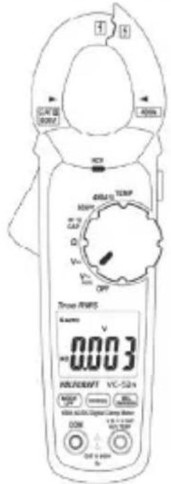
text_image
TROSE R/WIS 6 amms V 0.003 HOLDEN 125°C VCC 524A DC 10000 DC 10000 DC 10000 DC 10000 DC 10000 DC 10000 DC 10000 DC 10000 DC 10000 DC 10000 DC 10000 DC 10000 DC 10000 DC 524A DC 10000 DC 10000 DC 10000 DC 10000 DC 524A DC 10000 DC 10000 DC 10000 DC 524A DC 10000 DC 10000 DC 10000 DC 524A DC 10000 DC 10000 DC 10000 DC 524A DC 100C DC 100C DC 100C DC 524A DC 10C DC 1C DC 524A DC 1C DC 524A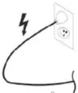
natural_image
Simple line drawing of a plug with a lightning bolt symbol (no text or labels)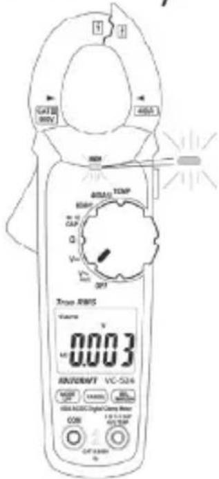
text_image
CAT 80V 400A 300V TEMP 800V MΩ CAP Q Vcc 0.1 0.2 0.3 0.4 0.5 0.6 0.7 0.8 0.9 0.10 0.11 0.12 0.13 0.14 0.15 0.16 0.17 0.18 0.19 0.20 0.21 0.22 0.23 0.24 0.25 0.26 0.27 0.28 0.29 0.30 0.31 0.32 0.33 0.34 0.35 0.36 0.37 0.38 0.39 0.40 0.41 0.42 0.43 0.44 0.45 0.46 0.47 0.48 0.49 0.50 0.51 0.52 0.53 0.54 0.55 0.56 0.57 0.58 0.59 0.60 0.61 0.62 0.63 0.64 0.65 0.66 0.67 0.68 0.69 0.70 0.71 0.72 0.73 0.74 0.75 0.76 0.77 0.78 0.79 0.80 0.81 0.82 0.83 0.84 0.85 0.86 0.87 0.88 0.89 0.90 0.91 0.92 0.93 0.94 0.95 0.96 0.97 0.98 0.99 1.00
Dimensions (L x l x H)....209 x 70 x 35 (mm)
9 Meetprocedure....148
9.1 De multimeter inschakelen ....148
9.2 Stroommeting "A"......149
9.3 Spanningsmeting "V" 152
9.4 Frequentiemeting en pulsduur....154
9.5 Temperatuurmeting....155
9.6 Meten van weerstand 157
9.7 Continuïteitstest ....158
9.8 Diodetest....159
9.9 Capaciteitsmeting 160
9.10 Contactloze wisselspanningsdetectie "NCV"....161
text_image
QR code image containing encoded data, no visible human-readable text9.2 Stroommeting "A"

text_image
CAT 2 RICH DCV 40kAmp TEMP 80mA CAP Q V OFF True RMS 0.0 WERTY VCC-524 MOSO OFF RANGE DCI DCI DCI DCI DCI DCI DCI DCI DCI DCI DCI DCI DCI DCI DCI DCI DCI DCI DCI DCI DCI DCI DCI DCI DCI DCI DCI DCI DCI DCI DCI DCI DCI DCI9.8 Diodetest