
VC515 - Multimeter VOLTCRAFT - Free user manual and instructions
Find the device manual for free VC515 VOLTCRAFT in PDF.

| Product type | Digital clamp meter (clamp multimeter) |
| Model | VC515 |
| Brand | Voltcraft |
| Dimensions (L x H x D) | approx. 35 x 216 x 67 mm |
| Weight | approx. 240 g (with batteries) |
| Power supply | 3 x 1.5 V AAA batteries |
| Display | 6000 counts, negative EBTN screen, True RMS |
| Measurement category | CAT III 600 V |
| Clamp opening | approx. 22 mm |
| AC/DC current measurement | 6 A / 160 A |
| AC/DC voltage measurement | 600 mV to 600 V |
| Resistance measurement | 60 MΩ max. |
| Capacitance measurement | 9.999 mF max. |
| Frequency measurement | 100 kHz max. |
| Temperature measurement | -20 to +250 °C (type K thermocouple) |
| Special functions | Diode test, continuity test, inrush current measurement, non-contact voltage detection (NCV), display hold, REL mode, min/max, LED flashlight |
| Maintenance and cleaning | Clean with a dry, lint-free cloth; do not use aggressive agents |
| Safety | Observe overvoltage categories, disconnect before battery change, use appropriate probes |
| Spare parts and repairability | Batteries, test leads and temperature probe included; repair by specialist only |
| Package contents | Clamp meter, 3 AAA batteries, carrying case, type K temperature probe, type K adapter, test leads, instruction manual |
Frequently Asked Questions - VC515 VOLTCRAFT
User questions about VC515 VOLTCRAFT
0 question about this device. Answer the ones you know or ask your own.
Ask a new question about this device
Download the instructions for your Multimeter in PDF format for free! Find your manual VC515 - VOLTCRAFT and take your electronic device back in hand. On this page are published all the documents necessary for the use of your device. VC515 by VOLTCRAFT.
USER MANUAL VC515 VOLTCRAFT
GB Operating Instructions
VC-515 160A AC/DC Clamp Meter
Item no: 3208845
F Mode d'emploi
natural_image
Technical line drawing of a mechanical component with no visible text or symbols1 Introduction.... 35
2 Operating Instructions for download.... 35
3 Intended use.... 35
4 Delivery contents ...... 36
5 Description of symbols.... 36
6 Safety instructions .... 38
6.1 User requirement.... 38
6.2 General.... 38
6.3 Handling.... 38
6.4 Operating environment.... 38
6.5 Operation.... 39
6.6 Battery compartment.... 39
6.7 Test leads and probes.... 39
6.8 Testing and measurement.... 40
6.9 Thermocouple 40
6.10 LED light....41
6.11 (Rechargeable) Batteries 41
6.12 Connected devices.... 41
7 Overview.... 42
7.1 Product....42
7.2 Display symbols 43
7.3 Function dial.... 44
8 Replacing the batteries.... 44
9 Operation.... 45
9.1 Power ON/OFF 45
9.2 Auto shut-off.... 45
9.3 Display hold.... 45
9.4 Minimum / maximum value display 45
9.5 Flashlight.... 46
9.6 REL mode 46
10 Testing and measurement.... 46
10.1 Current measurement (AC/DC) 46
10.2 Inrush current measurement 47
10.3 AC voltage measurement.... 48
10.4 DC voltage measurement.... 48
10.5 Resistance measurement.... 49
10.6 Diode test.... 49
10.7 Continuity test.... 50
10.8 Capacitance measurement 50
10.9 Frequency / duty cycle % measurement 51
10.10 Non-contact AC voltage measurement 51
10.11 Temperature measurement....52
11 Cleaning and care.... 53
12 Disposal....53
12.1 Product....53
12.2 (Rechargeable) batteries.... 54
13 Technical data 54
13.1 Product.... 54
13.2 Test leads and probes.... 55
13.3 Temperature sensor.... 55
13.4 Environment 55
13.5 Specifications 56
13.5.1 Accuracy 56
13.5.2 Calibration.... 56
13.6 AC voltage.... 56
13.7 DC voltage.... 56
13.8 AC Current 57
13.9 DC Current 57
13.10 Resistance.... 57
13.11 Diode....57
13.12 Continuity 58
13.13 Capacitance 58
13.14 Frequency 58
13.15 Temperature (auto-range).... 58
1 Introduction
Thank you for purchasing this product.
If there are any technical questions, please contact:
www.conrad.com/contact
2 Operating Instructions for download

Use the link www.conrad.com/downloads (alternatively scan the QR code) to download the complete operating instructions (or new/current versions if available). Follow the instructions on the web page.
3 Intended use
The product is a digital clamp meter and can be used to measure, test, and display various electrical parameters.
The product conforms to the following overvoltage categories:
■ MEASUREMENT CATEGORY II is applicable to test and measuring circuits connected directly to utilization points (socket outlets and similar points) of the low-voltage MAINS installation.
MEASUREMENT CATEGORY III is applicable to test and measuring circuits connected to the distribution part of the building's low-voltage MAINS installation.
The product is intended for indoor use only. Do not use it outdoors.
Contact with moisture must be avoided under all circumstances.
If you use the product for purposes other than those described, the product may be damaged.
Improper use can result in short circuits, fires, or other hazards.
The product complies with the statutory national and European requirements.
For safety and approval purposes, you must not rebuild and/or modify the product. Read the operating instructions carefully and store them in a safe place. Make this product available to third parties only together with the operating instructions.
All company names and product names are trademarks of their respective owners. All rights reserved.
4 Delivery contents
Clamp meter
3x 1.5 V AAA batteries
Carry case
K-Type temperature sensor probe
K-Type adaptor
Test leads (pair)
Operating instructions
5 Description of symbols

This product conforms to the required CE standards and is in compliance with applicable European (EU) directives.

This product is UK conformity assessed and meets applicable Great Britain directives.
CAT I
Measurement Category I: For measuring circuits of electrical and electronic equipment that is not directly supplied with a mains voltage (example: battery-operated devices, safety extra-low voltage systems, signal/control voltages)
CAT II
Measurement Category II: For measuring circuits of electrical and electronic equipment that is directly supplied with a mains voltage via a mains plug. This category also includes all lower categories (example: CAT I for measuring signal and control voltages).
CAT III
Measurement Category III: For measuring circuits of installations in buildings (example: mains sockets or sub-distributions). This category also includes all lower categories (example: CAT II for measuring electrical devices). Measuring in CAT III is only permitted with test probes with a maximum free contact length of 4 mm or with cover caps over the test probes.

Read the operating instructions carefully.

The symbol warns of hazards that can lead to personal injury.
The symbol warns of dangerous voltage that can lead to personal injury by electric shock.
Application around and removal from HAZARDOUS LIVE conductors is permitted. Personal protective equipment must be used.

Alternating current (AC)
Jaw alignment marks. To meet accuracy specifications the conductor must be aligned with these marks.

Earth ground

Direct current (DC)
6 Safety instructions

Read the operating instructions carefully and especially observe the safety information. If you do not follow the safety instructions and information on proper handling, we assume no liability for any resulting personal injury or damage to property. Such cases will invalidate the warranty/guarantee.
6.1 User requirement
The product must only be used by people who are familiar with the relevant regulations and understand the potential hazards. The use of personal protective equipment is recommended.
6.2 General
The product is not a toy. Keep it out of the reach of children and pets.
Do not leave packaging material lying around carelessly. This may become dangerous playing material for children.
If you have questions which remain unanswered by this information product, contact our technical support service or other technical personnel.
- Maintenance, modifications and repairs must only be completed by a technician or an authorised repair centre.
6.3 Handling
- Handle the product carefully. Jolts, impacts or a fall even from a low height can damage the product.
6.4 Operating environment
- Do not operate in potentially explosive areas.
- Do not operate in damp rooms or highly humid areas.
- Do not operate in areas affected by thunderstorms.
- Do not operate in areas with strong electromagnetic fields.
-
Do not operate in dusty areas.
Do not operate in areas where vapours, solvents or flammable gases are present. -
Do not place the product under any mechanical stress.
- Protect the appliance from extreme temperatures, strong jolts, flammable gases, steam and solvents.
- Protect the product from high humidity and moisture.
■ Protect the product from direct sunlight.
6.5 Operation
- Inspect the product for damage before every use. Do not use a damaged product.
- Avoid operation near strong magnetic/electromagnetic fields, transmitting antennas, or HF generators that can cause measurement distortion.
If it is no longer possible to operate the product safely, take it out of operation and protect it from any accidental use. DO NOT attempt to repair the product yourself. Safe operation can no longer be guaranteed if the product:
– is visibly damaged,
– is no longer working properly,
– has been stored for extended periods in poor ambient conditions or
– has been subjected to any serious transport-related stresses.
6.6 Battery compartment
- Do not use the product when the battery compartment is open or when the battery compartment cover is missing.
6.7 Test leads and probes
■ Always check the probes and leads for any sign of damage before each use. Do not use if damaged, replace immediately!
All connections between meter and earth potential must not exceed the specified voltage limits. For MAINS measurements, probe assemblies must meet EN 61010-031 standard with appropriate CAT rating and current capacity as defined in the equipment specifications table.
The cables have a wear indicator. If damaged, a second insulation layer in a different colour becomes visible. Do not use if this occurs, replace immediately!
- When taking measurements do not grip beyond the finger barrier or grip range markings on the probes.
- When taking CAT III measurements, probes with cover caps (max. 4 mm free contact length) must be used to avoid accidental short circuits.
When using the probes without cover caps, measurements between the meter and the earth potential must not be performed above the measuring category CAT II.
■ Prevent short circuits by ensuring test points/connections do not touch when taking measurements.
6.8 Testing and measurement
- Never use the meter on a circuit with voltages that exceed the category based rating of this meter. Do not exceed the maximum rated input limits.
- Do not use a damaged product. Check the product for signs of damage before use.
Consult an expert when in doubt about the operation, safety or connection of the product.
Exercise particular caution when working with voltages higher than 30 Vrms, 42.4 Vpk and 60 Vdc. Touching electrical conductors with these voltages can cause a fatal electric shock.
■ Always ensure that the product is set to the correct measurement mode before taking a measurement. Use the product at maximum range if the measured range is unknown.
To prevent an electric shock, do not touch the measuring points when taking measurements, either directly or indirectly.
■ Always remove the test probes from the measured object before changing the measurement range.
6.9 Thermocouple
Risk of electric shock! Prevent the temperature probe from coming into contact with voltage and current carrying components.
Do not exceed the rated maximum temperature of the thermocouple.
- Keep dry. Moisture can result in corrosion and cause measurement errors or thermocouple failure.
- Do not bend or crimp the junction or exposing it to corrosive chemicals.
6.10 LED light
- Do not look directly into the LED light!
- Do not look into the beam directly or with optical instruments!
6.11 (Rechargeable) Batteries
■ Correct polarity must be observed while inserting (rechargeable) batteries.
The (rechargeable) batteries should be removed from the device if it is not used for a long period of time to avoid damage through leaking. Leaking or damaged (rechargeable) batteries might cause acid burns when in contact with skin, therefore use suitable protective gloves to handle corrupted (rechargeable) batteries.
(Rechargeable) batteries must be kept out of reach of children. Do not leave (rechargeable) batteries lying around, as there is risk, that children or pets swallow them.
All (rechargeable) batteries should be replaced at the same time. Mixing old and new (rechargeable) batteries in the device can lead to (rechargeable) battery leakage and device damage.
(Rechargeable) batteries must not be dismantled, short-circuited or thrown into fire. Never recharge non-rechargeable batteries. There is a risk of explosion!
6.12 Connected devices
Also observe the safety and operating instructions of any other devices which are connected to the product.
7 Overview
7.1 Product
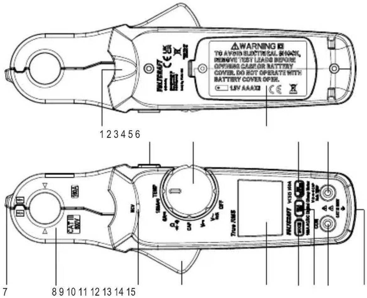
1 LED light 2
HOLD button
3 Function dial 4 Battery compartment
5 REL/INRUSH button
6 VΩ↔CAP Hz%TEMP socket
7 Non-contact voltage detector
8 Current clamp
9 Non-contact voltage LED
10 Clamp lever
11 Display
12 MODE button
13 MAX MIN button
14 COM socket
15 Tripod mount
7.2 Display symbols
| Symbol Description | |
| A | Current (amps) |
| AC | Alternating current |
| DC | Direct current |
| MAX | Maximum value |
| MIN | Minimum value |
| REL | Relative mode |
| Overload: range exceeded | |
| Minus sign | |
| Automatic shut-off active | |
| Low battery indicator | |
| Auto | Automatic range selection is active |
| -)) | Continuity check |
| Diode test | |
| Ω | Ohm (unit of electric resistance) |
| kΩ, MΩ | Kiloohm ( 10^3 ), Megaohm ( 10^6 ) |
| V | Volt (unit of electric voltage) |
| mV | Millivolt ( 10^-3 ) |
| A | Ampere (unit of current measurement) |
| mA, μA | Milliampere ( 10^-3 ), Microampere ( 10^-6 ) |
| mF, μF, nF | Millifarad ( 10^-3 ), Microfarad ( 10^-6 ), Nanofarad ( 10^-9 )Unit of electrical capacitance |
| °C | Celsius (unit of temperature) |
| °F | Fahrenheit (unit of temperature) |
| Hz | Hertz |
| % | Duty cycle percentage |
| HOLD | Display hold active |
| INRUSH | Inrush active |
7.3 Function dial
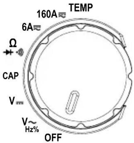
The function dial should be set to the correct range / function before each use.
■ Always set the switch to "OFF" when the product is not in use.
8 Replacing the batteries
Disconnect the product from any input signals before replacing the batteries.

Low battery voltage can affect the accuracy of readings.
- Replace the batteries when low battery indicator shows on the display.
Preconditions:
√ The power is switched OFF.
√ All circuits and test leads are disconnected from the meter.
- Open the battery compartment cover.
- Insert new batteries matching the polarity shown.
- Replace the battery compartment cover.
9 Operation
9.1 Power ON/OFF
The product is switched off when the function dial is in the position: OFF.
■ Switch the power OFF after use.
9.2 Auto shut-off
■ Auto shut-off is active by default, it is indicated by the Symbol.
This energy saving feature will shut power off after approximately 15 minutes of no activity.
To disable auto shut-off:
- Set the rotary switch to OFF.
- Press and hold the MODE button and then set the rotary switch to any position other than OFF.
→ The symbol will disappear and an alert will sound when disabled.
- Auto shut-off will reactivate after the power is switched OFF.
9.3 Display hold
Important:
- The display hold function freezes the display.
- The display hold should be switched OFF before taking measurements.
■ Press the HOLD button to switch display hold ON/OFF.
The hold icon HOL appear when display hold is ON.
9.4 Minimum / maximum value display
Note:
This function is available in all modes except continuity ( )
In this mode the display shows the "MIN" (minimum) or "MAX" (maximum) value measured.
- Press the MAX/MIN button repeatedly to toggle between modes.
→ The display will show "MAX" or "MIN" to indicate which mode is active.
- To disable it, press and hold the MAX/MIN button or rotate the function dial.
9.5 Flashlight
Press and hold the HOLD button to switch the light ON/OFF.
9.6 REL mode
- Press the REL button to set a relative mode by adjusting or offsetting the DCA (direct current amperage) or capacitance value to zero.
This ensures accurate measurements by eliminating any existing baseline values before performing a measurement.
10 Testing and measurement
10.1 Current measurement (AC/DC)

■ Disconnect the test leads before taking current measurements.
■ Unclamp the conductor if "OL" (overload) appears on the display.
If the range is not known, start with the higher range first then move to the lower range (if needed).
Risk of electric shock! Do not use the clamp on uninsulated conductors.
natural_image
Technical line drawing of a mechanical component with no visible text or symbols- Select a range using the function dial: 6A, 160A
- Press the MODE button to switch between AC/DC measurement.
- Clamp the jaws around the conductor to be measured, positioning it between the jaw alignment marks ▶ ◀.
→ The reading will show on the display.
- Carefully remove the clamp from the conductor after taking measurements.
5. Switch the power OFF after use.
Notes:
- The current sensing clamp is magnetized and a low reading may appear even when no conductor has been covered.
- Only one conductor should be covered by the current sensing clamp.
10.2 Inrush current measurement

- Disconnect the test leads before taking current measurements.
■ Unclamp the conductor if "OL" (overload) appears on the display.
If the range is not known, start with the higher range first then move to the lower range (if needed).
Risk of electric shock! Do not use the clamp on uninsulated conductors.
This function is available for AC current measuring modes.
Preconditions:
√ The device to be tested is powered OFF.
- Select a mode using the function dial: 6A\~, 160A\~.
- Clamp the jaws around the conductor to be measured, positioning it between the jaw alignment marks ▶ ◀.
- Press and hold the INRUSH button to initiate inrush current measurement.
→ "INRUSH" will show on the display.
- Switch on the device to be measured.
→ The inrush current (surge) will show on the display.
-
Carefully remove the clamp from the conductor after taking measurements.
-
Switch the power OFF after use.
10.3 AC voltage measurement
WARNING: Observe all safety precautions when working on live voltages.
- Set the function dial to: V ∼
- Press the MODE button to select AC voltage measurement.
→ The AC symbol will show on the display.
- Insert the test leads:
→ Black (-): COM input.
→ Red (+): _Hz input.
- Connect the test probes in parallel to the circuit under test.
→ The measurement will show on the display.
→ The display will show “OL” (overload) if the measuring range is exceeded or the circuit is interrupted.
- Disconnect the test leads and switch the power OFF after use.
10.4 DC voltage measurement
WARNING: Observe all safety precautions when working on live voltages.
-
Set the function dial to: V
-
Insert the test leads:
→ Black (-): COM input.
→ Red (+):VΩ→CAPHz%ηEMP.
- Connect the test probes in parallel to the circuit under test.
→ The measurement will show on the display.
→ The display will show “OL” (overload) if the measuring range is exceeded or the circuit is interrupted.
→ A minus sign “-” will appear in front of the reading if the polarities are reversed.
- Disconnect the test leads and switch the power OFF after use.
10.5 Resistance measurement
WARNING: Never test on a live circuit. Remove all power from the circuit and discharge any capacitors before testing.
- Set the function dial to: Ω
- Insert the test leads:
→ Black (-): COM input.
→ Red (+): VΩ←→CAP
Hz input.
- Connect the test probes to the part under test.
→ The reading will show on the display.
- Disconnect the test leads and switch the power OFF after use.
Notes:
- Check the test leads for continuity by touching them together. The value should be approx. 0.5 (inherent resistance).
10.6 Diode test

WARNING: Never test on a live circuit. Remove all power from the circuit and discharge any capacitors before testing.
- Set the function dial to: ▶
- Insert the test leads:
→ Black (-): COM input.
→ Red (+): VΩ 6+CAP Hz % TEM.
- Press the MODE button to select diode test.
→ That symbol will show on the display.
- Connect the test probes to the part under test.
→ The normal PN junction forward voltage will be shown in volts "V" on the display.
→ “OL” indicates that the diode is either reverse-biased or defective. Repeat the measurement using the opposite polarity.
- Disconnect the test leads and switch the power OFF after use.
10.7 Continuity test
WARNING: Never test on a live circuit. Remove all power from the circuit and discharge any capacitors before testing.
- Set the function dial to: .-1))
- Press the MODE button to select continuity test.
→ The symbol will show on the display.
- Insert the test leads:
→ Black (-): COM input.
→ Red (+): VΩ → CAP Hz input.
- Connect the test probes to the part under test.
→ The measurement will show on the display.
→ The display will show “OL” (overload) if the measuring range is exceeded or the circuit is interrupted.
→ If the resistance is <50 Ω, a tone will sound.
- Disconnect the test leads and switch the power OFF after use.
10.8 Capacitance measurement
WARNING: Never test on a live circuit. Remove all power from the circuit and discharge any capacitors before testing.
-
Set the function dial to: CAP.
-
Insert the test leads:
→ Black (-): COM input.
→ Red (+): _ input.
- Connect the test probes to the part under test.
→ The reading will show on the display. Large values can take several seconds to stabilize.
→ If "OL" appears in the display, remove and discharge the component.
- Disconnect the test leads and switch the power OFF after use.
Notes:
- The meter might display a fixed reading when no input is connected. This is the intrinsic compensation capacitance.
- For small capacitance measurements, press the REL button to set the reading to zero before taking a measurement.
10.9 Frequency / duty cycle % measurement
- Never exceed the rated input voltage.
- Set the function dial to: Hz%.
- Press the MODE button to switch between frequency (Hz) and duty cycle (%).
- Insert the test leads:
→ Black (-): COM input.
→ Red (+):VΩ↔CAP
Hz input.
- Connect the test probes to the part under test.
→ The measurement will show on the display.
- Disconnect the test leads and switch the power OFF after use.
10.10 Non-contact AC voltage measurement
Before use, always test the voltage detector on a known live circuit to ensure safe operation.
Insulation type, thickness, and distance from the voltage source may affect detection.
■ Always verify measurements using test leads before touching potentially energized circuits.
The non-contact voltage (NCV) detection function can detect AC voltage on conductors without touching them.
Due to the high sensitivity sensor, static electricity or other sources of energy may trigger the sensor. This is normal operation.
Preconditions:
√ The test leads are disconnected from the terminals.
-
Set the function dial to any position other than OFF.
-
Place the sensor tip near the conductor.
→ If AC voltage is present the LED will light up
Tip:
The conductors in electrical cord sets are often twisted. Slide the probe tip along the length of the cord to ensure it is positioned close to the live conductor.
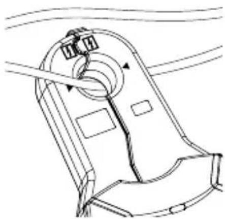
10.11 Temperature measurement

The temperature probe must not make contact with voltage and/or current carrying components.
■ Remove the thermocouple before changing to another measurement function.

Do not exceed the rated maximum temperature of the thermocouple. See section: Technical data.
- Check the polarity is correct when connecting the thermocouple.
- Set the function dial to: TEMP .
- Connect the thermocouple to the input terminals, ensuring correct polarity.
- Press the MODE button to switch between units of temperature measure (°C/°F).
- Apply the sensor to the part under test.
→ Wait for the reading to stabilize (up to approx. 30 seconds).
→ The measured temperature will show on the display.
11 Cleaning and care
Important:
- Do not use aggressive cleaning agents, rubbing alcohol or other chemical solutions. They damage the housing and can cause the product to malfunction.
-
Do not immerse the product in water.
-
Clean the product with a dry, fibre-free cloth.
12 Disposal
12.1 Product
This symbol must appear on any electrical and electronic equipment placed on the EU market. This symbol indicates that this device should not be disposed of as unsorted municipal waste at the end of its service life.
Owners of WEEE (Waste from Electrical and Electronic Equipment) shall dispose of it separately from unsorted municipal waste. Spent batteries and accumulators, which are not enclosed by the WEEE, as well as lamps that can be removed from the WEEE in a non-destructive manner, must be removed by end users from the WEEE in a non-destructive manner before it is handed over to a collection point.
Distributors of electrical and electronic equipment are legally obliged to provide free take-back of waste. Conrad provides the following return options free of charge (more details on our website):
in our Conrad offices
■ at the Conrad collection points
at the collection points of public waste management authorities or the collection points set up by manufacturers or distributors within the meaning of the ElektroG
End users are responsible for deleting personal data from the WEEE to be disposed of.
It should be noted that different obligations about the return or recycling of WEEE may apply in countries outside of Germany.
12.2 (Rechargeable) batteries
Remove batteries/rechargeable batteries, if any, and dispose of them separately from the product. According to the Battery Directive, end users are legally obliged to return all spent batteries/rechargeable batteries; they must not be disposed of in the normal household waste.
Batteries/rechargeable batteries containing hazardous substances are labelled with this symbol to indicate that disposal in household waste is forbidden. The abbreviations for heavy metals in batteries are:
Cd = Cadmium, Hg = Mercury, Pb = Lead (name on (rechargeable) batteries, e.g. below the trash icon on the left).
Used (rechargeable) batteries can be returned to collection points in your municipality, our stores or wherever (rechargeable) batteries are sold. You thus fulfil your statutory obligations and contribute to environmental protection.
Batteries/rechargeable batteries that are disposed of should be protected against short circuit and their exposed terminals should be covered completely with insulating tape before disposal. Even empty batteries/rechargeable batteries can contain residual energy that may cause them to swell, burst, catch fire or explode in the event of a short circuit.
13 Technical data
13.1 Product
Power supply.... 3x 1.5 V AAA batteries
Measurement category...... CAT III 600 V
Safety regulations...... EN 61010-2-032; EN 61010-1:2010
Voltage (AC/DC)..... max. 600 V
Current (AC/DC).... 160 A
Resistance..... max. 60 MΩ
Capacitance..... max. 9.999 mF
Frequency...... max. 100 kHz
Duty cycle...... max. 80 %
Display...... 6000 counts
True RMS .... yes
Display ...... Negative EBTN
Low battery indication......
Overrange Indication .... "OL"
Input impedance..... 10 MΩ (V/DC and V/AC)
Auto power off .... approx. 15 mins.
Clamp opening .... approx. 22 mm
Dimensions (W x H x D) .... approx. 35 x 216 x 67 mm
Weight .... approx. 240 g (with batteries)
13.2 Test leads and probes
Rated voltage .... CAT III 1000 V, CAT IV 600 V
Rated current.... 10 A
Protection class ...... II
13.3 Temperature sensor
Sensor..... K-Type thermocouple
Temperature (max.)..... 250 °C (482 °F)
Temperature range.... -20 to +250 °C (-4 to 482 °F)
13.4 Environment
Operating temperature ....+5 to +40 °C
Storage temperature..... -20 to +60 °C
Operating/storage humidity ..... max 80 % up to 31 °C (87 °F)
decreasing linearly to 50 % at 40 °C (104°F)
13.5 Specifications
13.5.1 Accuracy
- Specified accuracy ± (% of the reading + display error in counts).
Accuracy is maintained for 1 year at +23 °C (± 5 °C), ≤75 % RH (non-condensing).

The temperature condition of accuracy is 18 °C\~28 °C.
The fluctuation range of ambient temperature keeps within ±1 ^ .
If the temperature is < 18^ or >28^ , the additional error of temperature coefficient is: 0.1 × (specified accuracy) / °C.
13.5.2 Calibration
The recommended calibration interval is 1 year.
■ Calibration should only be performed by qualified personnel.
13.6 AC voltage
| Range (50-400 Hz) Resolution Accuracy | |
| 600 mV 0.1 mV ±(1.5 % +20) | |
| 6 V 0.001 V ±(1.5 % +5) | |
| 60 V 0.01 V | |
| 600 V 0.1 V |
■ Accuracy specified from 5% to 100% of the measuring range.
■ AC voltage bandwidth: 50 to 400 Hz (sine), 50 to 60 Hz (all wave).
13.7 DC voltage
| Range Resolution Accuracy | |
| 600 mV 0.1 mV ±(0.8 % +6) | |
| 6 V 0.001 V ±(1.0 % +6) | |
| 60 V 0.01 V | |
| 600 V 0.1 V |
13.8 AC Current
| Range (50/60 Hz) Resolution Accuracy | |
| 6 A 0.001 A ±(3.0 % +20) | |
| 160 A 0.1 A ±(3.0 % +8) |
■ Accuracy specified from 5% to 100% of the measuring range.
13.9 DC Current
| Range Resolution Accuracy | |
| 6 A 0.001 A ±(3.0 % +20) | |
| 160 A 0.1 A ±(3.0 % +8) |
13.10 Resistance
| Range Resolution Accuracy | |
| 600 Ω 0.1 Ω ±(1.0 % +6) | |
| 6 kΩ 0.001 kΩ ±(1.5 % +2) | |
| 60 kΩ 0.01 kΩ | |
| 600 kΩ 0.1 kΩ | |
| 6 MΩ 0.001 MΩ ±(2.5 % +3) | |
| 60 MΩ 0.01 MΩ ±(3.5 % +5) |
13.11 Diode
| Test current Open circuit voltage DC | ||
| 1 mA typical approx. | 3.3 V Typical | |
13.12 Continuity
| Threshold Test current | |
| <50 Ω <0.6 mA |
13.13 Capacitance
| Range Resolution Accuracy | |
| 99.99 nF 0.01 nF ±(5.0 % +20) | |
| 999.9 nF 0.1 nF ±(3.0 % +5) | |
| 9.999 μF 0.001 nF | |
| 99.99 μF 0.01 μF | |
| 999.9 μF 0.1 μF ±(4.0 % +10) | |
| 9.999 mF 0.001 mF ±(5.0 % +10) |
13.14 Frequency
| Range Accuracy | |
| 10 Hz - 100 kHz ( ± 1.5 % +2 ) |
13.15 Temperature (auto-range)
| Range Resolution Accuracy | ||
| -20 to 760 °C 1 °C ±(3% + 5 °C) | ||
| -4 to 1400 °F | 1 °F | ±(3% + 9 °F) |

Sommaire
France (email): technique@conrad-france.fr
natural_image
Technical line drawing of a mechanical component with no visible text or symbolsTension (CA/CC) .... max. 600 V
Courant (AC/DC) 160 A
√ De stroom is UITGESCHAKELD.
natural_image
Technical line drawing of a mechanical component with no visible text or symbolsTangopening...... ca. 22 mm
Afmetingen (B x H x D)...... ca. 35 x 216 x 67 mm
Gewicht..... ca. 240 g (met batterijen)
13.2 Testkabels en probes
Nominale spanning..... CAT III 1000 V, CAT IV 600 V
Nominale stroom 10 A
Beschermingsklasse...... II
Sensor.... K-type thermokoppel
Temperatuur (max.)...... 250 °C (482 °F)
Copyright by Conrad Electronic SE
*3208845_V2_0925_dh_mh_de 36028799349058059-1 I5/O2 en

This is a publication by Conrad Electronic SE, Klaus-Conrad-Str. 1, D-92240 Hirschau (www.conrad.com).
All rights including translation reserved. Reproduction by any method (e.g. photocopying, microfilming or the capture in electronic data processing systems) requires prior written approval from the editor. Reprinting, also in part, is prohibited. This publication reflects the technical status at the time of printing.
Copyright by Conrad Electronic SE
*3208845_V2_0925_dh_mh_en 36028799349058059-2 I5/O2 en

Copyright by Conrad Electronic SE
*3208845_V2_0925_dh_mh_fr 36028799349058059-3 l5/O2 en

Copyright by Conrad Electronic SE
*3208845_V2_0925_dh_mh_nl 36028799349058059-4 I5/O2 en
- Testing and measurement.... 46
- Cleaning and care.... 53
- Disposal....53
- Technical data 54
- Introduction
- Operating Instructions for download
- Intended use
- Delivery contents
- Description of symbols
- CAT I
- CAT II
- CAT III
- Safety instructions
- User requirement
- General
- Handling
- Operating environment
- Operation
- Battery compartment
- Test leads and probes
- Testing and measurement
- Thermocouple
- LED light
- (Rechargeable) Batteries
- Connected devices
- Overview
- Display symbols
- Function dial
- Replacing the batteries
- Preconditions:
- Operation
- Power ON/OFF
- Auto shut-off
- Display hold
- Important:
- Minimum / maximum value display
- Note:
- Flashlight
- REL mode
- Testing and measurement
- Current measurement (AC/DC)
- Switch the power OFF after use.
- Notes:
- Inrush current measurement
- AC voltage measurement
- DC voltage measurement
- Resistance measurement
- Diode test
- Continuity test
- Capacitance measurement
- Frequency / duty cycle % measurement
- Non-contact AC voltage measurement
- Tip:
- Temperature measurement
- Cleaning and care
- Disposal
- Product
- (Rechargeable) batteries
- Technical data
- Product
- Test leads and probes
- Temperature sensor
- Environment
- Specifications
- Accuracy
- Calibration
- AC voltage
- DC voltage
- AC Current
- DC Current
- Resistance
- Diode
- Continuity
- Capacitance
- Frequency
- Temperature (auto-range)
- Sommaire
- Testkabels en probes
Brand : VOLTCRAFT
Model : VC515
Category : Multimeter