
OnAir IP Panel Min - Lighting Chauvet - Free user manual and instructions
Find the device manual for free OnAir IP Panel Min Chauvet in PDF.
| Brand | Chauvet |
| Model | OnAir IP Panel Min |
| Category | Professional lighting |
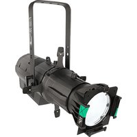
| Product type | Flat panel LED projector with DMX and wireless control |
| Power supply | Input 100-240 V~, 50/60 Hz; output 28 V DC, 50 W via external power supply |
| Protection rating | IP65 (temporary outdoor use, do not immerse) |
| Operating temperature | From -30 °C to 45 °C |
| Safety distance | Do not stare at less than 50 cm; do not place flammables within 20 cm |
| Control modes | Wired DMX (5-pin), Wireless CRMX™, RDM |
| DMX personalities | 1Ch, 3Ch, 4Ch, 5Ch, 6Ch, 8Ch, 10Ch, 11Ch, 15Ch, XYBasic(6), XYExtended(10) |
| Wireless range | Up to 300 m under optimal conditions |
| Update | Via USB flash drive through built-in USB port |
| Box contents | 4 fixtures, 4 Seetronic Powerkon IP65 power cords, 4 mini XLR DMX adapters, 4 yoke brackets, 4 Baby pin receivers, reference manual |
| Optional accessories | Filters, honeycomb, projector barn door |
| Maintenance | Clean with a dry cloth; do not use solvents; disconnect before cleaning |
| Safety | Do not open; use a safety cable when mounting overhead; do not connect to a dimmer; housing hot during operation |
| Warranty and repairability | Repair exclusively by the manufacturer or a qualified technician; replace damaged cable with a special cable provided by the manufacturer |
| Dimensions and weight | Not specified in the manual |
Frequently Asked Questions - OnAir IP Panel Min Chauvet
User questions about OnAir IP Panel Min Chauvet
0 question about this device. Answer the ones you know or ask your own.
Ask a new question about this device
Download the instructions for your Lighting in PDF format for free! Find your manual OnAir IP Panel Min - Chauvet and take your electronic device back in hand. On this page are published all the documents necessary for the use of your device. OnAir IP Panel Min by Chauvet.
USER MANUAL OnAir IP Panel Min Chauvet
Model ID: ONAIRPANELMINIP
About This Guide
The onAir IP Panel Min Quick Reference Guide (QRG) has basic product information such as mounting, menu options, and DMX values. Download the User Manual from www.chauvetprofessional.com for more details.
Disclaimer
The information and specifications contained in this QRG are subject to change without notice.
LIMITED WARRANTY
FOR WARRANTY REGISTRATION AND COMPLETE TERMS AND CONDITIONS PLEASE VISIT OUR WEBSITE.
For Customers in the United States and Mexico: www.chauvetlighting.com/warranty-registration.
For Customers in the United Kingdom, Republic of Ireland, Belgium, the Netherlands, Luxembourg, France, and Germany: www.chauvetlighting.eu/warranty-registration.
Chauvet warrants that this product shall be free from defects in material and workmanship under normal use, for the period specified in, and subject to the exclusions and limitations set forth in the full limited warranty on our website. This warranty extends only to the original purchaser of the product and is not transferable. To exercise rights under this warranty, you must provide proof of purchase in the form of an original sales receipt from an authorized dealer that shows the product name and date of purchase. THERE ARE NO OTHER EXPRESS OR IMPLIED WARRANTIES. This warranty gives you specific legal rights. You may also have other rights that vary from state to state and country to country. This warranty is valid only in the United States, United Kingdom, Republic of Ireland, Belgium, the Netherlands, Luxembourg, France, Germany and Mexico. For warranty terms in other countries, please consult your local distributor.
Safety Notes
These Safety Notes include important information about installation, use, and maintenance.
- The luminaire should be positioned so that prolonged staring into the luminaire at a distance closer than 19.7 in (50 cm) is not expected.
- If the external flexible cable or cord of this luminaire is damaged, it shall be replaced by a special cord or cord exclusively available from the manufacturer or his service agent.
- The light source contained in this luminaire shall only be replaced by the manufacturer or his service agent or a similar qualified person.
- The luminaire is intended for professional use only.
- DO NOT open this product. It contains no user-serviceable parts.
- DO NOT look at the light source when the product is on.
• To eliminate unnecessary wear and improve its lifespan, during periods of non-use completely disconnect the product from power via breaker or by unplugging it. - CAUTION: When transferring product from extreme temperature environments, (e.g. cold truck to warm humid ballroom) condensation may form on the internal electronics of the product. To avoid causing a failure, allow product to fully acclimate to the surrounding environment before connecting it to power.
- CAUTION: This product's housing may be hot when lights are operating.
• Mount this product in a location with adequate ventilation, at least 20 in (50 cm) from adjacent surfaces.
• DO NOT leave any flammable material within 7.87 in (20 cm) of this product while operating or connected to power. - USE a safety cable when mounting this product overhead.
- DO NOT submerge this product (IP65). Regular outdoor operation is fine.
- DO NOT operate this product if the housing, lenses, or cables appear damaged.
- DO NOT connect this product to a dimmer or rheostat.
- ONLY connect this product to a grounded and protected circuit.
- ONLY use the hanging/mounting bracket or the handles to carry this product.
- In the event of a serious operating problem, stop using immediately.
• The maximum ambient temperature is 113 °F (45 °C). Do not operate this product at higher temperatures. - The minimum startup temperature is -4°F (-20°C). Do not start the product at lower temperatures.
• The minimum ambient temperature is -22°F ( -30°C ). Do not operate the product at lower temperatures.
FCC Compliance
This device complies with Part 15 Part B of the FCC Rules. Operation is subject to the following two conditions:
-
This device may not cause harmful interference, and
-
This device must accept any interference received, including interference that may cause undesired operation.
Any changes or modifications not expressly approved by the party responsible for compliance could void the user's authority to operate the equipment.
RF Exposure Warning for North America, and Australia
Warning! This equipment complies with FCC radiation exposure limits set forth for an uncontrolled environment. This equipment should be installed and operated with a minimum distance of 20cm between the radiator and your body. This transmitter must not be co-located or operating in conjunction with any other antenna or transmitter.
Contact
Outside the U.S., U.K., Ireland, Benelux, France, Germany, or Mexico, contact your distributor to request support or return a product. Refer to Contact Us at the end of this QRG for contact information.
What is Included
• onAir IP Panel Min
• Seetronic Powerkon IP65 cable
• DMX mini XLR adapter
- Ball-head mount
- Baby pin receiver
• Quick Reference Guide
AC Power
This product has an auto-ranging external power supply that can work with an input voltage range of 100–240 VAC, 50/60 Hz and converts it to a 28 V DC, 50 W, 3-pin IP65 XLR output.
AC Plug
| Connection | Wire (U.S.) | Wire (Europe) | Screw Color |
| AC Live Black Brown Yellow/Brass | |||
| AC Neutral White Blue Silver | |||
| AC Ground | Green/Yellow | Green/Yellow | Green |
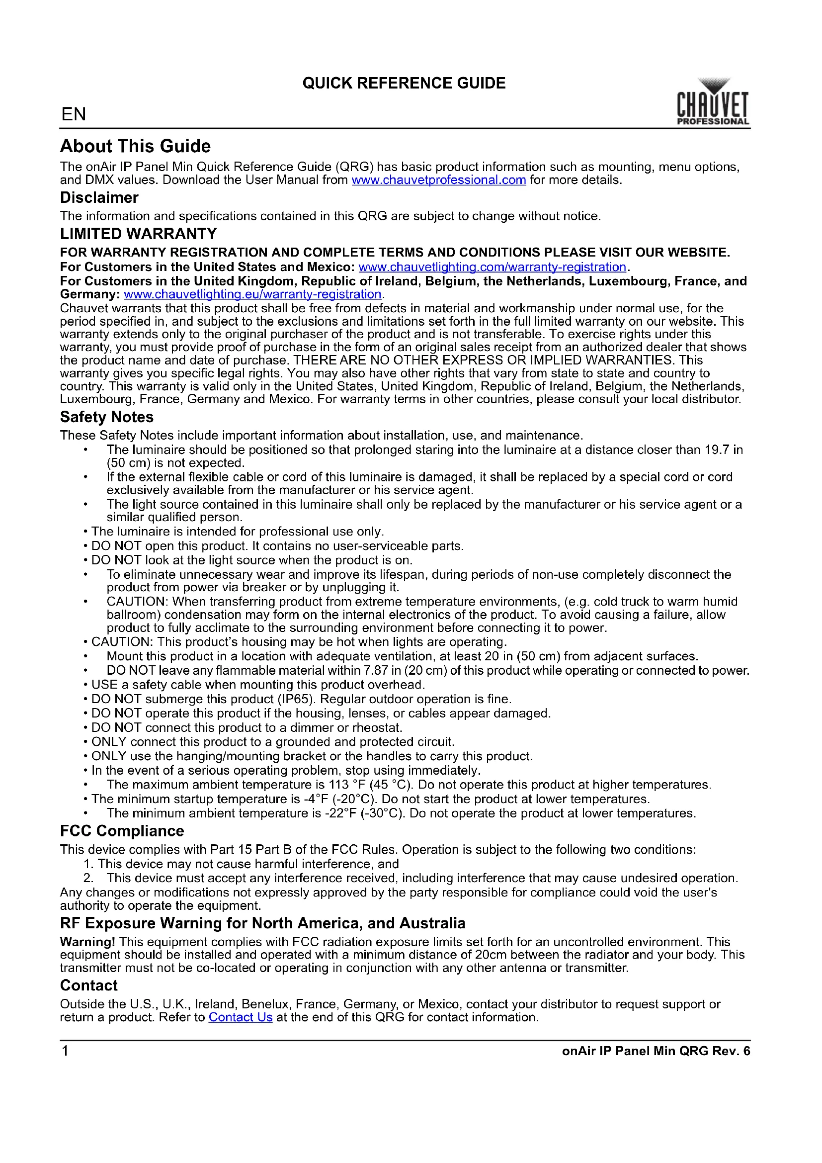
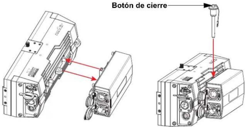
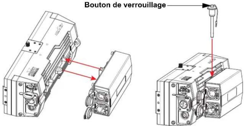
Installing the Power Supply
The power supply attaches to the onAir IP Panel Min with a retaining pin.
- Align the power supply so the loop on the back of the product and the loop on the power supply line up and fit into each other.
- Press and hold the latch button down on the retaining pin and insert it through the sets of loops on the product and power supply.
- Release the latch button.
DC Power
This product has a 3-pin IP65 XLR power input port that can work with an input voltage of 28 V DC, 50 W.

To eliminate unnecessary wear and improve its lifespan, during periods of non-use completely disconnect the product from power via breaker or by unplugging it.
Signal Connection
The onAir IP Panel Min will work with a controller or controller software using a 5-pin DMX or wireless Lumenradio CRMX™ connection. See the User Manual for information about how to connect and configure the product for these signals.
Control Personalities
The onAir IP Panel Min uses CRMX™ for its control personalities: 1Ch, 3Ch, 4Ch, 5Ch, 6Ch, 8Ch, 10Ch, 11Ch, 15Ch, XYBasic(6), and XYExtended(10).
DMX Connection
The onAir IP Panel Min will work with a DMX controller using a 5-pin serial DMX connection or a wireless CRMXTM connection. A DMX Primer is available from www.chauvetprofessional.com.
RDM (Remote Device Management)
Remote Device Management, or RDM, is a standard for allowing DMX-enabled devices to communicate bi-directionally along an existing DMX connection. Check the DMX controller's User Manual or with the manufacturer as not all DMX controllers have this capability. The onAir IP Panel Min supports RDM protocol that allows feedback to make changes to menu map options. Download the User Manual from www.chauvetprofessional.com for more details.
USB Software Update
The onAir IP Panel Min allows for software update through USB using the built-in USB port. To update the software using USB flash drive, do the following:
- Power on the fixture and plug the flash drive into the USB port.
- Once the flash drive has been detected, the message "Upgrade Firmware" will be displayed. Press
.
- If a different message appears on the display, search for the updated software in the Main Menu (Update Firmware) and select from Only This Unit, Multiple Units, or Other Fixture Type. A list of the software update files will be displayed.
- Select the file that needs to be uploaded. The message "Are you sure?" will be displayed. Press
. - If the selected file is correct, the upgrade will be completed. Restart the fixture.
- If the selected file is incorrect, the upgrade will fail, and the display will go back to the main interface. Repeat steps 1-3 using the correct file.

The “Other Fixture Type” option can only be selected for connected products compatible with the Upload 03 (the first 2 digits of the item code must be 03).
Wireless Operation
In optimal conditions, the onAir IP Panel Min can operate up to 300 m (900 ft) away from the CRMX ™ transmitter, The CRMX ™ receiver in the onAir IP Panel Min must be paired with the CRMX ™ transmitter for wireless operation.
Initial Setup
- Turn the CRMX TM transmitter on.
- Connect the CRMX ™ transmitter to a DMX controller.
- Place the onAir IP Panel Min within 300 m from the CRMX ™ transmitter.
- Turn the onAir IP Panel Min on.
Configuration
- From the onAir IP Panel Min's control panel, go to DMX Address.
- Select the start address, as with any other DMX compatible product.
- Go to Wireless Setting >Receive On/Off.
- Select On. (The Signal Strength Indicator will show a ? in front of the bars)
- Press the reset button on the CRMX™ transmitter. (The Signal Strength Indicator on the onAir IP Panel Min will show a 4 in front of the bars for 3 seconds while a connection is established.)
Product Pairing
If the onAir IP Panel Min has already been paired with the CRMX ™ transmitter, the Signal Strength Indicator on top of the display will show the strength of the signal. In this case, the onAir IP Panel Min is ready to work in Wireless mode.
Pairing the onAir IP Panel Min and a New CRMX TM Transmitter
- From the onAir IP Panel Min control panel, go to Wireless Setting >Receive Reset.
- Select Yes.
- From the CRMX™ transmitter, press
. The signal indicator on the transmitter will flash. - Once the transmitter has found the onAir IP Panel Min, the signal indicator on the CRMX ™ transmitter will illuminate solid.
- The display screen on the onAir IP Panel Min will show the strength of the signal.

CRMX™ operation can be interrupted or inhibited by people or liquid masses, including water or snow, between the transmitter and receiver. For best results, keep the area between the transmitter and receiver clear of any liquid masses.
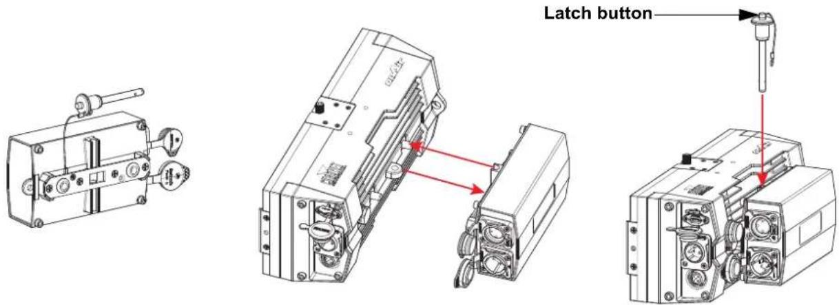
Mounting
Before mounting this product, read the Safety Notes.
Mounting Diagram
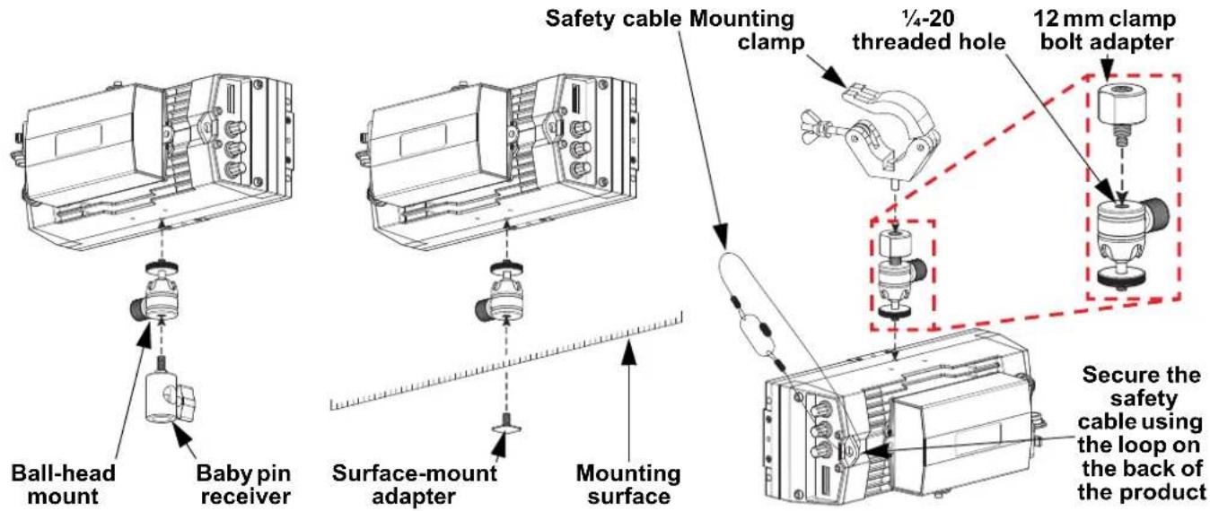
Accessories
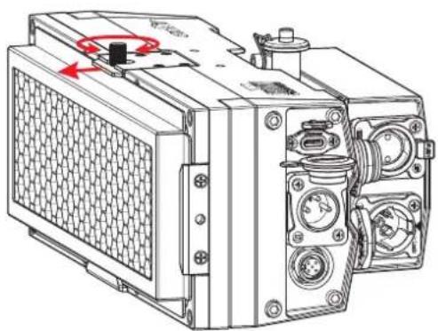
The onAir IP Panel Min has an accessory slot for a filter or a honeycomb (sold separately). The optional barndoor (sold separately) fits neatly over the front of the product.
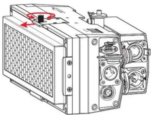
To install a filter or the honeycomb:
- Slide the filter or honeycomb into the accessory slot.
- Loosen the thumbscrew on top of the product and slide the panel out to secure the filter or honeycomb.
- Tighten the thumbscrew.
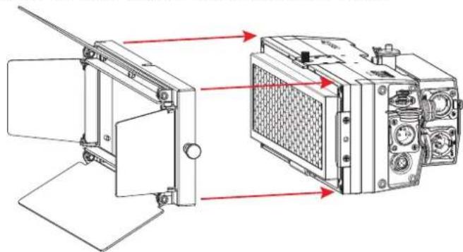
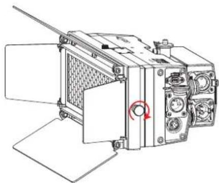
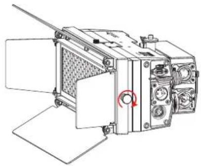
To install the barndoor:
- Place the barndoor frame around the front of the product.
- Tighten the knob to secure the barndoor in place.
Home Screen
The home screen of the onAir IP Panel Min shows the current settings and status of the product.
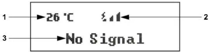
Number Description
1 Current product temperature
2 Current wireless signal status
3 Bottom line shows details of the current control mode
On Board Control
Pressing
- onAir IP Panel Min
• Cable de Seetronic Powerkon IP65 - Adaptador DMX mini XLR

Para instalar la visera:

Pantalla de inicio
Alimentation CC

Écran d'accueil
Om de barndoor te installeren:

Startscherm

- About this guide
- Disclaimer
- Limited warranty
- For warranty registration and complete terms and conditions please visit our website
- Safety notes
- Fcc compliance
- Rf exposure warning for north america, and australia
- Contact
- What is included
- Ac power
- Installing the power supply
- Dc power
- Signal connection
- Control personalities
- Dmx connection
- Rdm (remote device management)
- Usb software update
- Wireless operation
- Initial setup
- Configuration
- Product pairing
- Pairing the onair ip panel min and a new crmx tm transmitter
- Mounting
- Accessories
- Home screen
- Number description
- On board control
- On board control menu
- Control panel description
- Dmx values
- Acerca de esta guía
- Exención de responsabilidad
- Garantía limitada
- Notas de seguridad
- Cumplimiento de la fcc
- Advertencia de exposición a rf para américa del norte y australia
- Contacto
- Qué va incluido
- Para instalar la visera
- Pantalla de inicio
- Alimentation cc
- Écran d'accueil
- Startscherm
Brand : Chauvet
Model : OnAir IP Panel Min
Category : Lighting