CONFORT24 - Boiler EAS Electric - Free user manual and instructions
Find the device manual for free CONFORT24 EAS Electric in PDF.
User questions about CONFORT24 EAS Electric
0 question about this device. Answer the ones you know or ask your own.
Ask a new question about this device
Download the instructions for your Boiler in PDF format for free! Find your manual CONFORT24 - EAS Electric and take your electronic device back in hand. On this page are published all the documents necessary for the use of your device. CONFORT24 by EAS Electric.
USER MANUAL CONFORT24 EAS Electric
natural_image
Line drawing of a vertical panel with an oval vent and control buttons (no text or symbols)text_image
CONFORT24
text_image
EAS ELECTRICEscanee para ver este manual en otros idiomas y actualizaciones Scan for manual in other languages and further updates Manuel dans d'autres langues et mis à jour Manual em outras línguas e actualizações
CONTENIDO
Página
1. PRECAUCIONES 2
1.1 SÍMBOLOS 2
1.2 AVISOS GENERALES 3
1.3 EXPLICACIONES GENERALES
text_image
Technical diagram of an electrical enclosure with numbered components for identification
text_image
Technical diagram of an industrial machine with numbered components labeled 26, 27, and 28.text_image
Diagram of a circular device with labeled components and directional arrows indicating flow or movement.natural_image
Pure technical line drawing of a mechanical or electrical component without any text, numbers, or symbolsSistema

natural_image
Pure electrical circuit lines without any symbolsCaldera
3.2 DESEMBALAJE
text_image
Diagram of a cardboard box with scissors and numbered label 1, likely for instructional or labeling purposes.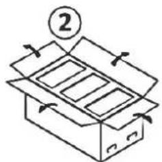
text_image
Diagram of an open box with a numbered label and directional arrows indicating movement or flow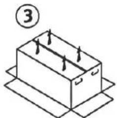
natural_image
Isometric diagram of a rectangular box with internal arrows, placed on a flat base (no text or symbols)text_image
Technical diagram of a mechanical assembly with numbered components for identification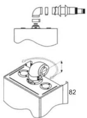
natural_image
Technical line drawing of a mechanical assembly with pipe and housing components (no text or symbols)natural_image
Technical line drawing of a mechanical assembly with no visible text or symbols
natural_image
Line drawing of a hand pouring liquid into a tray with three circular chambers (no text or symbols)natural_image
Symbol of a trash bin crossed with a diagonal line and a horizontal bar below (no text or labels)natural_image
Pure electrical circuit lines without any symbolsnatural_image
Black electronic device with green control panel and three icons (no text or symbols)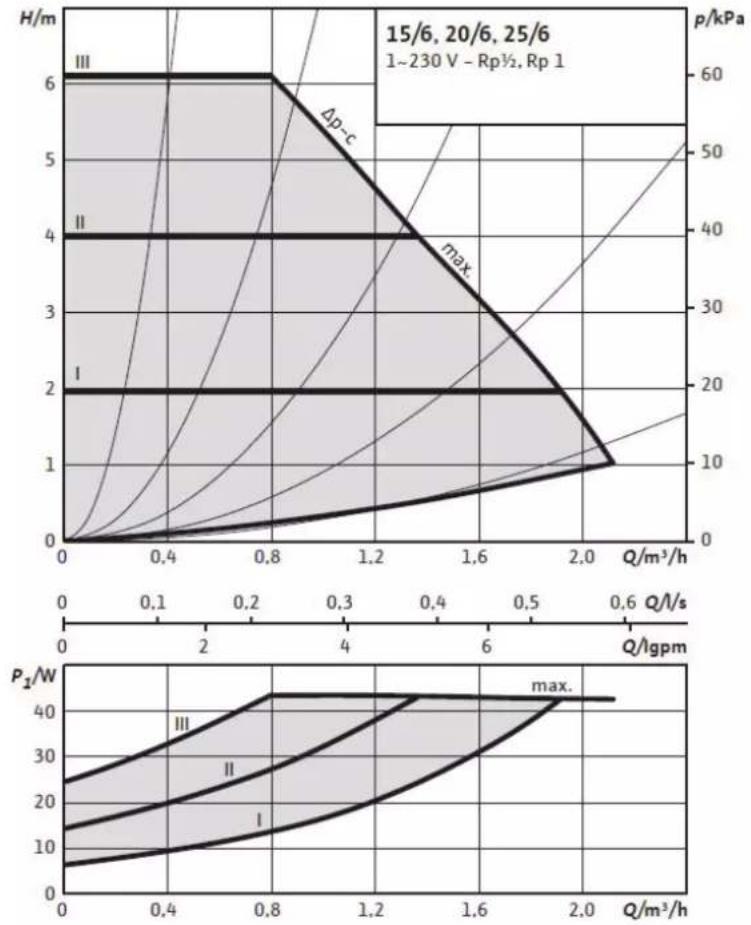
line
| Q/m³/h | H/m (I) | H/m (II) | H/m (III) | p/kPa (max) | |--------|---------|----------|-----------|------------| | 0.0 | 0 | 0 | 0 | 0 | | 0.4 | 0 | 0 | 6 | 60 | | 0.8 | 0 | 0 | 6 | 60 | | 1.2 | 0 | 0 | 4 | 40 | | 1.6 | 0 | 0 | 2 | 20 | | 2.0 | 0 | 0 | 1 | 10 | | 2.4 | 0 | 0 | 0 | 0 |
natural_image
Black rectangular device with green circular indicator and three white icons on the right (no text or symbols)
line
| Q/m³/h | H/m (I) | H/m (II) | H/m (III) | p/kPa (max) | P₂/W (I) | P₂/W (II) | P₂/W (III) | |--------|---------|----------|-----------|------------|----------|-----------|------------| | 0.0 | 0.0 | 0.0 | 0.0 | 0.0 | 5.0 | 10.0 | 25.0 | | 0.4 | 0.0 | 0.0 | 6.7 | 60.0 | 10.0 | 20.0 | 35.0 | | 0.8 | 2.0 | 4.0 | 6.7 | 50.0 | 15.0 | 25.0 | 40.0 | | 1.2 | 1.5 | 3.5 | 5.5 | 40.0 | 20.0 | 30.0 | 45.0 | | 1.6 | 1.0 | 3.0 | 4.5 | 30.0 | 25.0 | 35.0 | 50.0 | | 2.0 | 1.0 | 2.5 | 3.5 | 20.0 | 30.0 | 40.0 | 55.0 | | 2.4 | 1.0 | 2.0 | 2.5 | 15.0 | 35.0 | 45.0 | 60.0 | | 2.8 | 1.0 | 1.5 | 1.5 | 10.0 | 40.0 | 50.0 | 65.0 | | 3.2 | 1.0 | 1.0 | 1.0 | 5.0 | 45.0 | 55.0 | 70.0 | | 3.6 | 1.0 | 1.0 | 1.0 | 2.5 | 50.0 | 60.0 | 75.0 | | 4.0 | 1.0 | 1.0 | 1.0 | 1.0 | 55.0 | 65.0 | 80.0 | | 4.4 | 1.0 | 1.0 | 1.0 | 0.5 | 60.0 | 70.0 | 85.0 | | 4.8 | 1.0 | 1.0 | 1.0 | 0.2 | 65.0 | 75.0 | 90.0 | | 5.2 | 1.0 | 1.0 | 1.0 | 0.1 | 70.0 | 80.0 | 95.0 | | 5.6 | 1.0 | 1.0 | 1.0 | 0.1 | 75.0 | 85.0 | 100.0 | | 6.0 | 1.0 | 1.0 | 1.0 | 0.1 | 80.0 | 90.0 | 105.0 | | 6.4 | 1.0 | 1.0 | 1.0 | 0.1 | 85.0 | 95.0 | 110.0 | | 6.8 | 1.0 | 1.0 | 1.0 | 0.1 | 90.0 | 100.0 | 115.0 | | 7.2 | 1.0 | 1.0 | 1.0 | 0.1 | 95.0 | 105.0 | 120.0 | | 7.6 | 1.0 | 1.0 | 1.0 | 0.1 | 100.0 | 110.0 | 125.0 | | 8.0 | 1.0 | 1.0 | 1.0 | 0.1 | 105.0 | 115.0 | 130.0 | | 8.4 | 1.0 | 1.0 | 1.0 | 0.1 | 110.0 | 120.0 | 135.0 | | 8.8 | 1.0 | 1.0 | 1.0 | 0.1 | 115.0 | 125.0 | 140.0 | | 9.2 | 1.0 | 1.0 | 1.0 | 0.1 | 120.0 | 130.0 | 145.0 | | 9.6 | 1.0 | 1.0 | 1.0 | 0.1 | 125.0 | 135.0 | 150.0 | | 10.0 | 1.0 | 1.0 | 1.0 | 0.1 | 130.0 | 140.0 | 155.0 | | >16 | <2 | <2 | <2 | <2 | <45 | <48 | <52 | | >24 | <2 | <2 | <2 | <2 | <65 | <68 | <72 | | >32 | <2 | <2 | <2 | <2 | <85 | <88 | <92 | | >48 | <2 | <2 | <2 | <2 | <95 | <98 | <98 | | >64 | <2 | <2 | <2 | <2 | <98 | <98 | <98 | | >88 | <2 | <2 | <2 | <2 | <98 | <98 | <98 | | >136 | <2 | <2 | <2 | <2 | <98 | <98 | <98 | | >192 | <2 | <2 | <2 | <2 | <98 | <98 | <98 | | >248 | <2 | <2 | <2 | <2 | <98 | <98 | <98 | | >336 | <2 | <2 | <2 | <2 | <98 | <98 | <98 | | >484 | <2 | <2 | <2 | <2 | <98 | <98 | <98 | | >646 | <2 | <2 | <2 | <2 | <98 | <98 | <98 | | >888 | <2 | <2 | <2 | <2 | <98 | <98 | <98 | | >136* (Q/l*); P=ρ/ψ; Rp/½; Rp/₁; max; P₁/ψ; max; Q/l*).
natural_image
Black square electronic device with three monitors and control buttons (no text or symbols)17. CONDICIONES DE GARANTÍA
8. SAFETY SYSTEMS AND TROUBLE SHOOTING 20
8.1 NO BURNING, MISLEADING FLAME 21
8.2 LOW – HIGH WATER PRESSURE 22
8.3 OVERHEAT LIMIT TERMOSTAT 22
8.4 ANTI CALCER SYSTEM 22
9. GAS PRESSURE SETTING 23
10. CLEANING AND MAINTENANCE 23
- IMPORTANT INFORMATIONS FOR YOUR SAFETY 23
- EFFICIENT USE OF BIOLERS IN TERMS OF ENERGY CONSUMPTION 24
- POINTS TO BE CONSIDERED WHILE MOVING AND TRANSPORTING 25
- USAGE WITH LPG
- ANNEX: SPECIFICATIONS 27
- ANNEX: CIRCULATION PUMP 28
- GUARANTEE CONDITIONS 32
Dear Customer,
We advise you to read this guide carefully. This guide is an important source for both installation and utilization. Moreover, since it contains practical and technical information, you can easily benefit from it.
Please keep this manual for using when needed.
ATTENTION; THESE DEVICES CAN OPERATE WITH NATURAL GAS, LPG OR WITH PROPAN. Contact with an Eas Electric Authorized Service to change the type of gas which is specified on the package. The operations which are performed by unqualified services or people invalidate the product's warranty.
ATTENTION; gas transformation should be performed by the authorized service according to the criteria in the attached table.
1.SAFETY WARNING
1.1 Symbol Key

This symbol expresses the risk of personal injury unless taking care of warnings.

This symbol expresses the conditions can cause harms on environment, animals or goods unless taking care of warnings.
Do not open the protective cover of the device.
⚠️ Electric shock as a result of the contact with electrical items.
Personal injury like burnt as a result of contact with overheated surfaces or cut as a result of contact with sharp surface.
Do not remove the device from the place of mounting, do not disconnect (Get in contact with authorized service)
⚠ Flood as a result of demounted water installation.
△ Explosion, fire or poisoning danger as a result of demounted gas installation. Protect the energy cable against damages.
⚠️ Electric shock danger as a result of contact with not izolated open wires. Do not leave tools or staff on the device.
⚠️ Injury resulted from falling objects from device because of vibration.
△ Harms on things or animals resulted from falling objects from device because of vibration.
Do not climb on device.
Personal injury as a result of fall down with device or fall down of device itself. Damage risk on staff under device as a result of fall down from the place installed.
Do not stamp on chair, stool, ladder or other things which are not strong enough.
⚠️ Personal injury resulted from falling down from heigh or cuts can be resulted from a rapid closing of ladder.
Do not clean the device unless switching it to off position or disconnecting energy link.
△ Use the device for only heating the house and getting hot water. Damage risk resulted from inappropriate using and overloading.
△ Damage risk of the place resulted from inappropriate using.
Do not allow children or people who can not use the device, to intervene in device.
△ Damage to device risk resulted from wrong use.
Disconnect the main energy connection, shut down the main gas valve, open all the windows, move away the place and call help in case of burning smell or smoke from device.
⚠️ Personal injury from bursts, breathing smoke or poisoning.
Shut down the main gas valve, open all windows, avoid from sparkling and move away call for help if there is a gas smell in place.
Explosion, fire or poisoning danger.
Pay attention not harming the electric cables and pipes inside wall while making holes on wall for metal hangers.
Electric shock as a result of the contact with electrical items.
Explosion and fire danger results from gas pipe puncure.
△ Flood risk results from water pipe puncture.
Suitable profiled cables must be used in all electric connections.
Fire risk results from overheated law profiled cables.
1.2 GENERAL WARNINGS
- Follow the instructions in this manual while using the device. Manufacturer can not be held responsible from breakdowns and damages from wrong use.
- Start-up, maintenance and repairs can be done by only Eas Electric AUTHORISED SERVICES. Otherwise device will go out of guarantee and manufacturer will not be responsible for breakdowns or damages.
- It is dangerous and forbidden to use flammable/combustible materials at the site of the boiler.
- Thinner, benzine etc. flammable materials must be kept away from the place that boiler runs.
- Device must be mounted to a suitable location at a distance of at least 2.5 meters from each side of easily flammable household goods and flammable materials.
- Minimum ambient temperature must be 5^ C when the boiler installed in a partly covered place like balcony. When the ambient temperature is lower, boiler must be isolated within a proper keeping stuff.
- Only authorised service can intervene the all parts and sections that (when) leakage is observed.
1.3 GENERAL EXPLANATIONS
Our CONFORT Condensing Boiler provides the heating by central boiler heating system and radiators connected to the sytem, and provides hot water by heat exchanger.
Installation and services must be in accordance with recent standards, directives and instructions which will be explained in this manual. Producer cannot be held liable for damages caused from wrong installation and usage.
ATTENTION; Installation, start-up and maintenance must be done by EAS Electric staff or staff authorized by Eas Electric.
ATTENTION; In case of a leakage, firstly close the gas inlet valve and ventilate the environment, then call authorised service immediately.
WARNING !
This instruction manual is extremely important and must be kept as a reference guide.
Follow the instructions on manual to run the boiler. Manufacturer is not responsible for the failures and damages resulted from improper use.
Optimum lifetime of the boiler is 15 years. It should be replaced with a new one at the end of this period.
The boiler is under warranty of the manufacturer if the product complies with conditions specified in the warranty.
It is recommended to making annual periodic maintenance in accordance with data on maintenance chapter. Only Eas Electric authorised services can intervene the boiler.
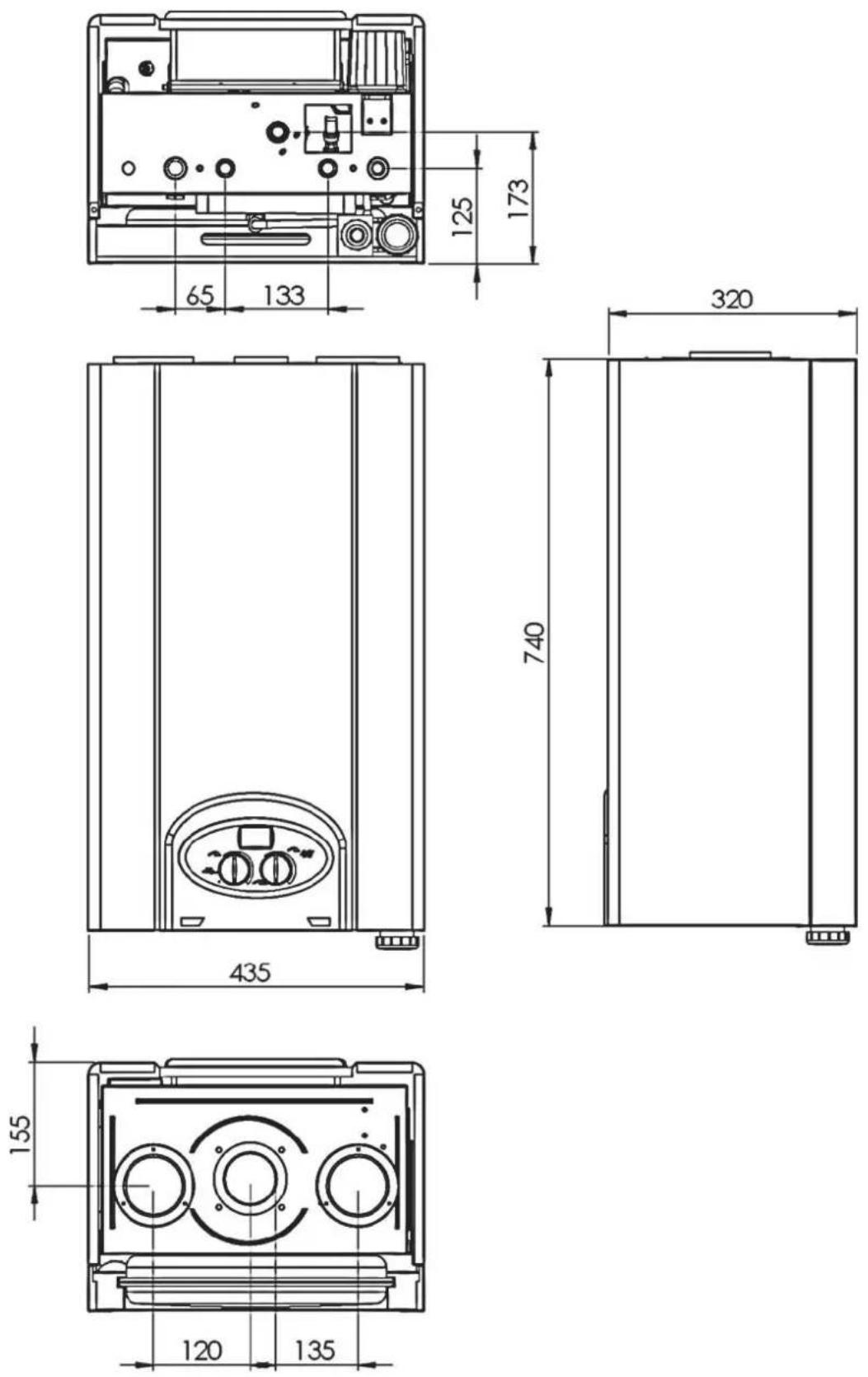
2. INTRODUCTION OF THE DEVICE
2.1 APPEARANCE AND EXTERNAL DIMENSIONS
2.2 INTERNAL STRUCTURE AND COMPONENT LIST

text_image
Technical diagram of an electrical enclosure with numbered components for identification
text_image
Technical diagram of an industrial machine with numbered components labeled 26, 27, and 28.- Presostat
- Fan
- Burning Room Isolation and Side Cap
- Bimetal Limit Thermostat
- Ionisation Electrode
- 3 Way Motor Valve
- Gas Valve Modulation Bobin
- Heat Sensor Of The System
- Hot Water Circuit Temperature Sensor
- Pressure Gauge (Transducer)
- Plate Exchanger
- Gas Valve
- Filling Valve
-
Water Flow Sensor
-
Condensing Water Reservoir
- Circulation Pump
- Ignition Electrode
- Burner
- Combustion Chamber
- Heating Circuit Exchanger
- Top Smoke Chest
- Rekuperator (Condensing Exchanger)
- Fresh Air Entrance Flange
- Chimney Outlet
- Chimney Limit Thermostat
- Expansion Tank
- 3 Bar Safety Ventile
- Panel Bottom Support Sheet
2.3 CONTROL PANEL
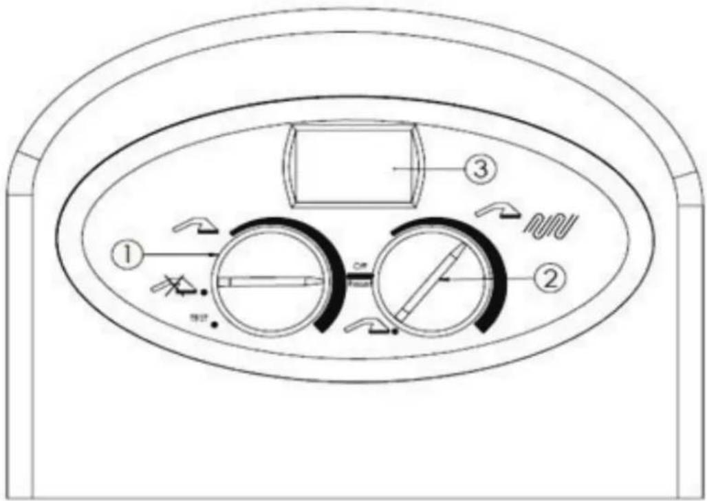
text_image
Technical diagram of a circular device with labeled components and directional arrows indicating flow or movement.All functions required to run the boiler is done via two buttons on the control panel. These functions are seen on the LCD screen. All failure reports are seen on screen via specific codes.
A. P1 KEY

DHW Adjustment: Temperature of the DHW is adjusted. Desired temperature flashes on the screen.

DHW function is OFF. Note: The boiler does not produce DHW.
TEST: Mode of adjustment by AUTHORISED SERVICE.
B. P2 KEY
OFF - RESET: The boiler is functionally switched off. In case of failure it is used as a reset. Safety against frost and congestion are enabled.
Winter Mode: Both DHW and heating function is on. Heating system adjustments are done. Desired temperature flashes on the screen. DHW is priority.
Summer Mode: Only DHW function is on.
C. LCD SCREEN:
It shows running and failure conditions with the warning codes on screen. These codes are:
WARNING CODE EXPLANATION SOLUTION
E04 Low or high water pressure (page 22)
E01 No Flame (page 22)
E02 Limit thermostat (page 22)
E03 Chimney Thermostat Call authorised service.
E37 Circulation Failure Call authorised service.
E05 Heating system sensor error (page 23)
E035 Misleading Flame Call authorised service.
text_image
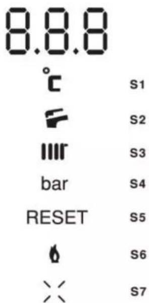
8.8.8 °c S1 F S2 I I I R S3 bar S4 RESET S5 Ø S6 × S7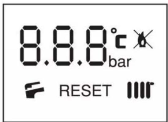
text_image
8.8.8°c bar RESET IIIS1 : °C (temperature) symbol.
S2 : (KS) DHW is heating.
S3 : (MS) Central System is heating
S4 : Bar (water pressure ) symbol.
S5 : Manual reset is required.
S6 : Burning initiated, boiler is running.
S7: No burning
3. INSTALLATION DATA
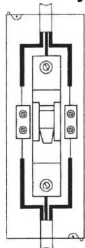
3.1 ELECTRICITY CONNECTION
• The boiler works with 230 v. 50 Hz. alternative current.
- Please make sure that the fuse supplied along with the boiler is installed maximum 10 cm. away from the boiler.
- An electricity cable of 3x1,5 mm ^2 must be laid out by an auth electrician.
- The boiler works with ground line. Both for your and the boiler's safety, please make sure that the grounding is done properly.
- Please make the phase, neutral and ground line connection as shown on the schema.
IMPORTANT
- The boiler does not operate when the connection is done improperly.
- The cable of the boiler must be connected as shown:
Brown: Connect this to phase cable.
Blue: Connect this to neutral cable.
Yellow-Green: Connect this to ground cable.
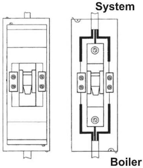
text_image
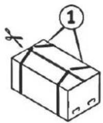
System Boiler3.2 OPENING THE BOX

- Put the box on the floor as arrows showing down and open the box by cutting packing belts.
- Open the covers by folding on 4 sides as shown in figure.
- Turn down the box as shown in figure and pull box to up and remove it from the box.
3.3 WALL MOUNTING
The installation of the gas boiler must be done by authorized dealers. Start-up operation must be done by Eas Electric AUTHORISED SERVICE. Your device will become out of guarantee if the installation and operation terms indicated on this manual are not applied.
3.4 POINTS TO BE CONSIDERED AT INSTALLATION
- Pipings must be cleaned before the installation of the device.
- The gas connection of the unit must be done properly and controlled for any leakages.
- Condensing boilers run on closed burning chamber principle. They supply the air from outside for burning, and then exhausts the bur gases to the environment. For this reason, the exhaust gas outlet pipe must be installed in contact with the outside atmosphere.
- Exhaust gas pipes must not be put in closed areas where there is no air circulation.
- Wall mounted boilers must be installed vertically on a strong wall that can carry it.
- The unit must not be installed in connection with dirty and oily flue where the kitchen appliances are connected to.
- Specific spaces must be left around the unit for the authorized service to intervene in the event of a technical breakdown or maintenance. You can find the minimum spaces required for installation indicated below.
- Installation accessories provided along with the boiler (wall plug, screw and hooks) must be used during the installation.
- The proper installation checked by a water gauge is necessary for the healthy operation of the boiler.
- The condensate drain hose of the appliance must be connected to a suitable water drain as specified in this manual. (see page 11)
3.5 SPACES TO BE LEFT DURING INSTALLATION
Following ranges must be left along with installation in order to reach internal parts of the device during maintenance and possible malfunctions.)
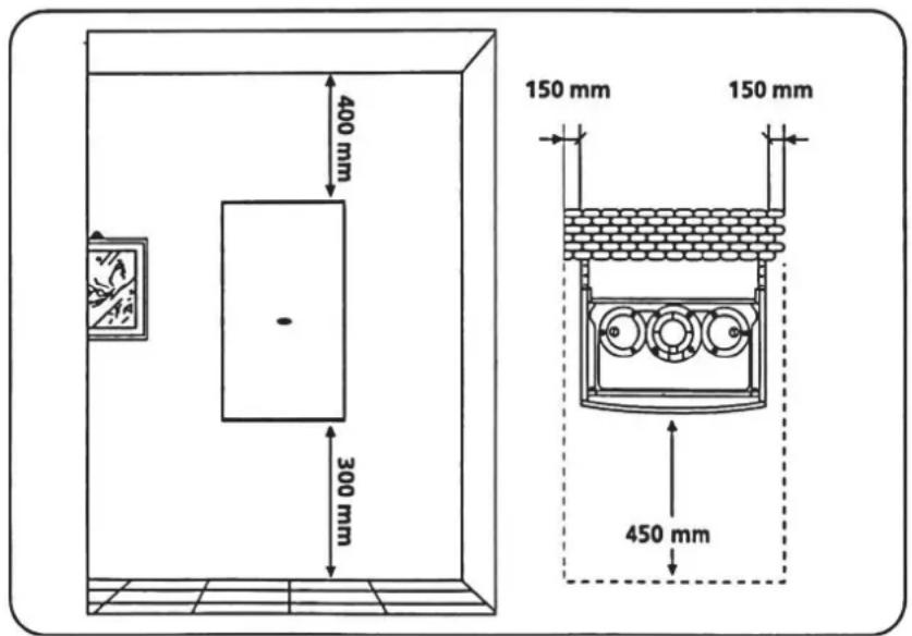
text_image
400 mm 300 mm 150 mm 150 mm 450 mm3.6 CONNECTION OF CONDENSATE WATER DISCHARGE
The condensate discharge water hose from the boiler must be connected to a suitable acid-resistant pipe (plastic) at an angle of 2.5^ towards the floor. The pipe must be at least in 22 mm diameter and connected to a suitable drain. The connection can be made in the following ways:
i) Connection can be done to a sink water drain inside the house. At least 75 mm siphon connection should be made when connecting, and install it in such a way that no other fluids can rise to the condensate collection of the boiler.
ii) Connection can be done to a water drain outside the house.
The condensation water discharge connection should be made according to the following figures.
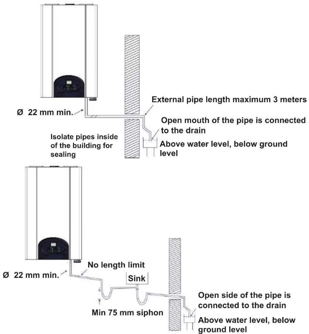
text_image
External pipe length maximum 3 meters Open mouth of the pipe is connected to the drain Above water level, below ground level Ø 22 mm min. Isolate pipes inside of the building for sealing Ø 22 mm min. No length limit Sink Min 75 mm siphon Open side of the pipe is connected to the drain Above water level, below ground level
text_image
OK SOCAL GAZ 3/4 1/2" GAS 3/4" 1/2" 3/4 Condensation Water OutletFor such connections, the valid standards in that country must be complied and the local public and health authorities' regulations, if any, must also be observed. Condensation outlet pipe should be placed very carefully.
The pipe should not break when placed.
Pipe should not take the shape of a goose neck.
It should be clean.
Use the pipes in accordance with the applicable rules for the discharge of condensate water.
Since the condensation water pH is close to 2 (acidity), necessary precautions should be taken before any work is carried out. (Protective gloves)
3.7 INSTALLATION CONNECTION DIAGRAM
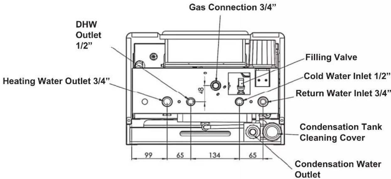
text_image
DHW Outlet 1/2" Heating Water Outlet 3/4" Gas Connection 3/4" Filling Valve Cold Water Inlet 1/2" Return Water Inlet 3/4" Condensation Tank Cleaning Cover 99 65 134 65 Condensation Water Outlet3.8 INSTALLATION CONNECTIONS
- At DHW function, please make sure that the pressure of the city water network on cold water inlet side is not more than 6 Bars. If the net pressure is more than 6 Bars, a pressure regulator must be added order to run DHW system, minimum pressure level of the network must be 0.8 Bar.
- In order to provide a good circulation in heating function, installation pipes must be selected accordingly and diameter structure must not be allowed at elbow passage. In selection of the pipe diameters, pipe resistance above the pump capacity should be avoided by using the pump pressure curve.
- When there is an excessive pressure increase at heating system, the security ventile operates in order to discharge the excessive water.
- When radiator thermostatic valves are installed in the heating system and when the heat balance is provided at all isolated sections, if the thermostatic valves turn off the system: Automatic by-pass system immediately runs in order to provide the minimum circulation in heat exchanger.
- Gas installation connection must be done by gas tightness pastes. Never use linen or teflon. The gas inlet pressure mentioned in this manual must be strictly obeyed.
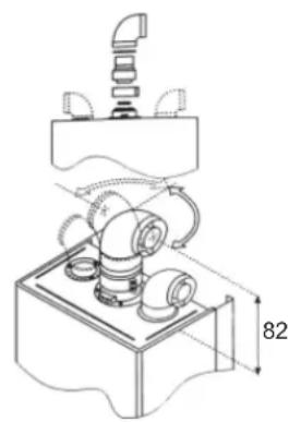
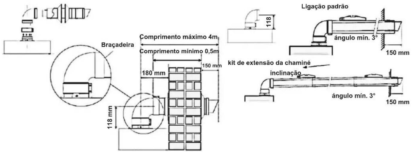
3.9 CHIMNEY CONNECTION
Mounting of condensing chimney kit must be in accordance with mounting schema which is given with boiler.

text_image
Technical diagram of a soldering iron with numbered components for assembly or maintenance reference.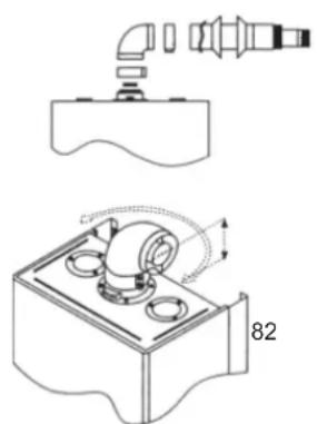
natural_image
Technical diagram showing a mechanical assembly with pipe connection and component layout (no text or symbols)- Elbow Set
- Extra Pipe Joint
- Clips 37mm
- Condensing Chimney
5.Elastic Wall Badge
natural_image
Technical line drawing of a mechanical assembly with no visible text or symbols
text_image
Clamp Maximum length 4 meter Minimum length 0.5 meter 180 mm 150 mm 118 mm Standart connection min slope 3° 150 mm chimney kit extension slope min slope 3° 150 mm
text_image
ascending slope 52 mm 3° 4000 mm maxATTENTION: Chimney must be installed upward with a slope of 3% angle in order to provide the leaking of condensing water flow into the condensing tank in the boiler. Chimney should not come into contact with flamm materials and get through flammable wall material.
Part of the chimney which stays inside the wall, must be maximum 60 cm in behind connections and must be maximum 40 cm in sidelong connections.
Allowed maximum chimney length is 4 m. If otherwise, please consult the manufacturer for technical information.
Important: There is an air protestat inside the boiler to shutdown the boiler in case of a possible failure inside of the chimney. In this case, please contact your local service.
4. FLUSHING TO THE SYSTEM AND MONITORING WATER PRESSURE
Water pressure of the heating system is digitally displayed on LCD screen.
To display the pressure, turn P1 Knob to TEST position, and move P2 SUMMER position on the control panel (page 7). Water pressure will displayed as bar (unit of pressure). Air must be purged from radiators in the initial flushing process. Please follow these steps to start initial flushing:
1- Open all purgers in central boiler installation and radiators.
Attention: Rotate directions of water evacuation holes and place a pot under each purger in order to prevent environment from water damages.
2- Open the filling valve (page 12) which is placed underneath the boiler and start filling water into the system.
3- Close all the purgers when blister-free water starts to come from purgers.
4- Continue to flush until the system pressure comes up to 1,5 Bar, then turn off the filling valve.
Attention: It is recommended to make initial flushing with at least 2 people. While one person is controlling the radiators and closing the purgers, the other one can control the pressure by standing over the boiler and close the filling valve if needed.
In case of water shortage in closed circuit system after running of the boiler, it is necessary to add water to system by opening filling valve. Radial must be checked if there is air in them or not.
5. START-UP
Boiler must be put into service by only Technical Services in order to run the boiler efficient and safe, also for the validation of guarantee conditions.
5.1 PRE-CONTROLS BEFORE START-UP
- The gas type and its pressure must be controlled.
- Automatic purger fuse on the circulation pump must be loosened.
- The pressure inside the system must be controlled from the manor. The pressure must be around 1,5 Bar.
- In order to dispose the air from all of the system, take out the screw in front of the pump. By this way, whether the pump mill is congested or not can be controlled and any air that is congested can be discharged.
- Dispose the air from the purgers on radiators.
6.Discharge the air in the hot water system by turning on hot water tap. - Check the installation of hermetic flue kit.
- Check whether all valves in the system are turned on.
- Check that the accuracy of condensate drain connection.
Start-up must be done by the Eas Electric Authorised Services to validate the warranty conditions.
The below must be applied:
ATTENTION; The condensation reservoir of the boiler must be filled with water during the first start-up. To ensure this, add 1/4 It of water from the boiler flue outlet as shown in the figure below before first operating.

natural_image
Line drawing of a hand pouring liquid into a tray with three circular chambers (no text or symbols)ATTENTION; If there is not enough water in the condensation reservoir of the boiler, device can run by emitting smoke for a while.
- Make sure that fuse switch, which enables the energy connection of boiler, is open. If the boiler has waited for a long time after the installation in OFF mode without start-up, authorised service must check the circulation pump in case of any squeezing.
- Turn on all the valves on boiler and installation pipes.
- Closed circuit water pressure must be at 1,5 bar (page 15).
- Choose the position of use with the help of P1 and P2 buttons on control panel (page 7 and 18).
- You can start using the boiler by setting temperature at desired level.
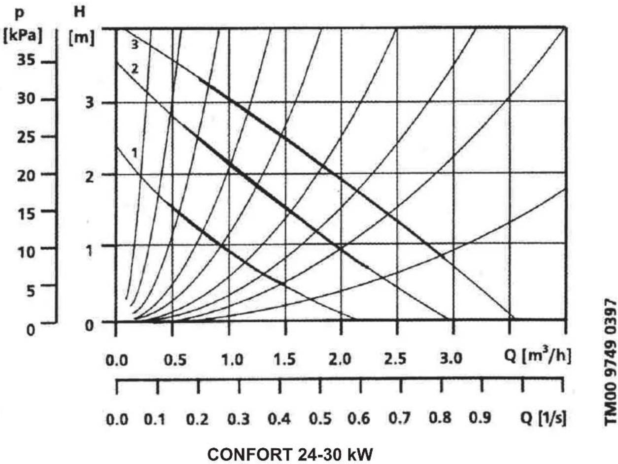
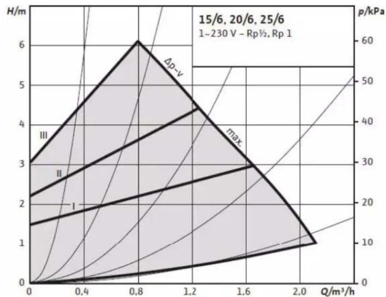
5.3 PRESSURE CURVE of THE CIRCULATION PUMP
3 speed circulation pump is used in Eas Electric CONFORT Boiler. It is possible to set the circulation with these three speeds according to resistance required by installation.
line
| Q [m³/h] | H [m] | p [kPa] | | -------- | ----- | ------- | | 0.0 | 0 | 0 | | 0.5 | 1 | 5 | | 1.0 | 2 | 10 | | 1.5 | 3 | 15 | | 2.0 | 4 | 20 | | 2.5 | 5 | 25 | | 3.0 | 6 | 30 | | 3.5 | 7 | 35 | | 4.0 | 8 | 40 | | 4.5 | 9 | 45 | | 5.0 | 10 | 50 | | 5.5 | 11 | 55 | | 6.0 | 12 | 60 | | 6.5 | 13 | 65 | | 7.0 | 14 | 70 | | 7.5 | 15 | 75 | | 8.0 | 16 | 80 | | 8.5 | 17 | 85 | | 9.0 | 18 | 90 | | 9.5 | 19 | 95 | | 10.0 | 20 | 100 | | 10.5 | 21 | 105 | | 11.0 | 22 | 110 | | 11.5 | 23 | 115 | | 12.0 | 24 | 120 | | 12.5 | 25 | 125 | | 13.0 | 26 | 130 | | 13.5 | 27 | 135 | | 14.0 | 28 | 140 | | 14.5 | 29 | 145 | | 15.0 | 30 | 150 | | 15.5 | 31 | 155 | | 16.0 | 32 | 160 | | 16.5 | 33 | 165 | | 17.0 | 34 | 170 | | 17.5 | 35 | 175 | | 18.0 | 36 | 180 | | 18.5 | 37 | 185 | | 19.0 | 38 | 190 | | 19.5 | 39 | 195 | | 20.0 | 40 | 200 | | 20.5 | 41 | 205 | | 21.0 | 42 | 210 | | 21.5 | 43 | 215 | | 22.0 | 44 | 220 | | 22.5 | 45 | 225 | | 23.0 | 46 | 230 | | 23.5 | 47 | 235 | | 24.0 | 48 | 240 | | 24.5 | 49 | 245 | | 25.0 | 50 | 250 | | 25.5 | 51 | 255 | | 26.0 | 52 | 260 | | 26.5 | 53 | 265 | | 27.0 | 54 | 270 | | 27.5 | 55 | 275 | | 28.0 | 56 | 280 | | 28.5 | 57 | 285 | | 29.0 | 58 | 290 | | 29.5 | 59 | 295 | | 30.0 | 60 | 300 | | 30.5 | 61 | nanoscale, no data provided in the image. The y-axis is labeled 'H' and the x-axis is labeled 'Q' with values ranging from -∞ to +∞ (with some values not explicitly labeled). The labels '1', '2', '3', '4', '5' are also present but do not correspond to the plotted data series in this view.6. USING OF THE BOILER
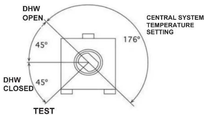
P1 KEY SETTING MODES
text_image
DHW OPEN 45° CENTRAL SYSTEM TEMPERATURE SETTING 176° DHW CLOSED 45° TESTP2 KEY SETTING MODES
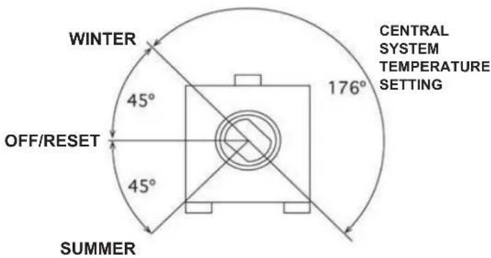
text_image
WINTER 45° OFF/RESET 45° SUMMER CENTRAL SYSTEM TEMPERATURE SETTING 176°SUMMER MODE:
When Summer mode is chosen, boiler runs only to get DHW (30-60°C) set by P1 key when there DHW demand.
Opening of the hot water tap is automatically perceived and boiler generates the hot water needed. Provides constant temperature comfort with full modulation system.
In stand by mode when hot water is not demanded, pressure value of the water inside boiler is displayed on the screen.
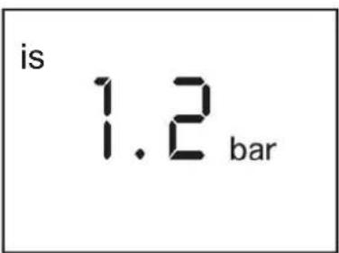
text_image
is 1.2 barOFF/RESET MODE:
In Off mode, boiler is shut down.
In OFF mode, automatic protective functions below are in use:
• DHW Freezing Protection
• Central System Freezing Protection
- Pump Squeezing Protection
• 3 Way Valve Squeezing Protection
When manually reset error occurs, key should be placed to RESET position and then should be placed to previous position (before reset position. This process resets your device. In this condition “OFF” is displayed on LCD screen.
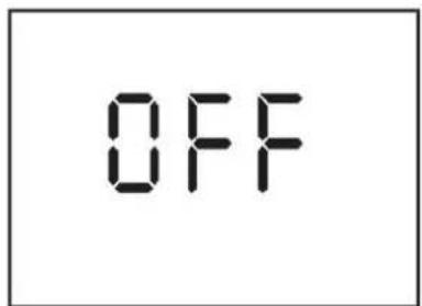
text_image
OFFATTENTION!: Electricity, gas and water connections should not be disconnected in order to run the freezing protection function and other automatic protection functions.
Attention!: If the boiler won't be used for a long time, nobody will be in the house and there is a possibility of frost, discharge the water from heating circuit, close the gas valve of the boiler and disconnect the electricity connection. Freezing protection function will be non-utilizable and damaged as a result of disconnecting gas and electric without discharging the water completely.
Discharging Water from the Boiler :
Water inside the boiler can be discharged completely by using the discharging valve which is at the bottom point of boiler heat system. Check the manometer while discharging the water, and be sure that manometer shows 0 “zero” and finally be sure that water leakage is done.
WINTER MODE
When the boiler is in this mode, it runs according central system temperature which is adjusted by P2 key (30-85°C). Boiler provides the adjusted temperature automatically. Provides constant temperature comfort with full modulation system. DHW production is priority at the winter mode. If it is required, DHW can be moved to OFF position and only central system heating can provide. Water pressure value is displayed in this condition and conditions of no need of heat.
to
1.2 bar
CENTRAL SYSTEM (CS) TEMPERATURE SETTING
CS temperature is set to intended value by turning P2 key. Temperature increases in clockwise, decreases counter clock wise. Adjusted temperature flashes on screen while adjusting. When it is at intended degree, setting is recorded at the end of this process and completed.
68°C
After setting, water temperature in boiler is displayed on boiler screen.
DOMESTIC WATER (DHW) TEMPERATURE SETTING
DHW temperature is set to intended value by turning P1 key. Temperature value increases clockwise, decreases counter clock wise.
Adjusted temperature flashes on screen during setting. When it is at intended degree, setting is recorded at the end of this process and completed. After setting, water temperature in boiler is displayed on boiler screen.
46 ^ c
7. ELECTRICITY CONNECTION SCHEMA
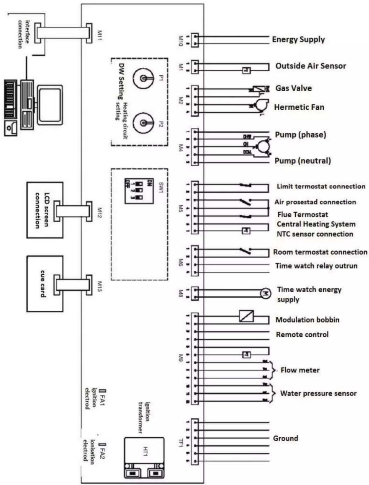
flowchart
graph TD
    A["Ground"] --> B["Water pressure sensor"]
    B --> C["Flow meter"]
    C --> D["Remote control"]
    D --> E["Modulation bobbin"]
    E --> F["Time watch energy supply"]
    F --> G["Room termostat connection"]
    G --> H["NTC sensor connection"]
    H --> I["Flue Termostat"]
    I --> J["Air prosestad connection"]
    J --> K["Limit termostat connection"]
    K --> L["Pump (neutral)"]
    L --> M["Pump (phase)"]
    M --> N["Hermetic Fan"]
    N --> O["Gas Valve"]
    O --> P["Outside Air Sensor"]
    P --> Q["Energy Supply"]

    subgraph System Modules
        R["SW1"] --> S["M12"]
        S --> T["M13"]
        T --> U["Cue card"]
        U --> V["F41"]
        V --> W["F42"]
        W --> X["Invention transformer H11"]
        Y["SW1"] --> Z["M12"]
        Z --> AA["M13"]
        AA --> AB["Cue card"]
        AB --> AC["F41"]
        AC --> AD["F42"]
        AD --> AE["Invention electron"]
        AF["SW1"] --> AG["M12"]
        AG --> AH["M13"]
        AH --> AI["Cue card"]
        AI --> AJ["F41"]
        AJ --> AK["F42"]
        AK --> AL["Invention electron"]
8. SAFETY SYSTEMS AND TROUBLE SHOOTING
Eas Electric's boiler is accompanied by all security measures necessary for your comfort.
8.1 NO BURNING, MISLEADING FLAME
This problem occurs when there is no burning on the burner and E01 warning code appears on LCD screen.
What to Do: After making sure that the gas valve is on and the gas supply is available, change P2 key to reset position, then readjust it the preferred mode. Repeat this process until burning is provided, if this does not work, please call the authorised service.
8.2 LOW – HIGH WATER PRESSURE
When the pressure in the system is below 0,7 bar or above 2,5 bar; the boiler does not operate and E04 warning code appears on the LCD screen.
What to Do: The heating system pressure is arranged at desired level by filling valve. You can view the pressure of the water on the LCD screen. Switch P1 key to TEST position and P2 key to SUMMER position.
8.3 OVERHEAT LIMIT TERMOSTAT
This problem occurs when the heating system temperature is over 95^ C, and E02 warning code appears on the LCD screen.
What to Do: When the water temperature decreases to 60^ C, the boiler will work again. If this failure occurs two times successively, please call an authorised service.
8.4 ANTI CALCER SYSTEM
This system provides an indirect control against calcer formation. The water temperature in the heating circuit of the plate exchanger cannot exceed 70 degrees, regardless of the flow rate and temperature. By this way, occurrence of calcer is prevented.
8.5 PREVENTION AGAINST FROST
When the temperature in the heating system drops down to 5^ C, inside the boiler there is a security system that automatically switches on the burner. When the water temperature reaches 45^ C, burners are switched off. In order for this system to work and protect your device against freezing, the electrical connection of the device, the gas valve and the installation valves must be in open position. This system is active when the device is off.
8.6 When a sensor failure occurs in hot water system, E06/E12 warning code appears on LCD screen. Call authorized service.
8.7 When a sensor failure occurs in heating system, E05 warning code appears on the LCD screen. Call authorized service.
8.8 When there is an over pressure in the heating system, there is an available security ventile to dispose the water.
8.9 If there are thermostatic valves on each radiator, even when all thermostatic valves are switched off, there is an automatic by pass system in order to provide the passage of minimum water flow.
The gas pressure settings given in the following table should be adjusted while changing gas type of the device.
IMPORTANT NOTE: This modification operation can only done by an authorised service.
Diameter of the injectors must be suitable for fuel type used.
Natural Gas Injector diameter: 1.35mm
LPG/Propan Injector diameter: 0,75mm
Attention: Be sure about the resealing of the parts that were unsealed while gas modification operation. Test to see if there is gas leakage after the operation.
| 24 KW | 30 KW | ||
| NATURAL GAS | Maximum gas pressure (mbar) | 9,7 | 9,7 |
| Minimum gas pressure (mbar) | 1,45 | 1,45 | |
| LPG | Maximum gas pressure (mbar) | 20 | 20 |
| Minimum gas pressure (mbar) | 3,5 | 3,5 |
10. CLEANING AND MAINTENANCE
It is recommended to make yearly maintenance to increase the lifespan, efficient usage, energy saving and protect quality at the beginning. Maintenance must be done by only Eas Electric Autorised Service. Intervention of private services except autorised services, is extremely dangerous and causes out of warranty coverage. It is recommended to make yearly maintenance before the heating season.
| MAINTENANCE | YEARLY | BIYEARLY |
| Cleaning hermetic flue presostat and venturi | √ | - |
| Cleaning heat exchanger | √ | - |
| Cleaning burning room, fan and inside pipe | √ | - |
| Checking gas and electric connections | √ | - |
| Checking gas flow rate and pressure | √ | - |
| Checking all smoke pipes | √ | - |
| Cleaning the burner and examining flame performance | √ | - |
| Checking water system | √ | - |
| Waste Gaz Analyse | - | √ |
| Checking situation of parts | - | √ |
| Checking Gas Way Armatures | - | √ |
| Checking connection part of heat exchanger | - | √ |
| Checking electronic parts | - | √ |
| Checking Fan Working Function | - | √ |
√ Necessary
Not necessary -
ATTENTION!
11. IMPORTANT INFORMATIONS FOR YOUR SAFETY
Please keep these warnings to prevent potential dangers!
In Case of a Gas Leakage
Do not put light fire and prevent formation of sparking
Open the doors and windows
Turn off the gas valve
Call the authorised installation company
Obey the security protocols of the gas distribution company
Cut the electricity connection by a separate fuse or switch
Turn off the valves of the fuel pipe
In case of fire, appropriate fire extinguisher must be used.
When Performing Maintainance or Repair
When working on the heating system or the boiler itself, there should be no current on these. The main switch or fuse of the system must be switched off and necessary precautions must be taken for preventing their reoperation.
Turn off the gas valve and prevent it is unwanted re-opening.
Installation of Extra Equipments
Extra equipments that is not controlled together with the boiler might have negative effect on the system. Damages that might occur as a result of the use of such items are out of guarantee conditions and manufacturer is not liable what so ever.
natural_image
Symbol of a trash bin crossed with no visible text or labelsDISPOSAL: Do not dispose this product as unsorted municipal waste. Collection of such waste separately for special treatment is necessary.
The european directive 2012/19 /UE on wasted electrical and electronic equipments (WEEE), requires that household electrical appliances must not be disposed of in the normal unsorted municipal waste stream. appliances must be collected separately in order to optimize the recovery and recycling of the materials they contain, and reduce the impact on human health and the environment.
The crossed out “wheeled bin” symbol on the product reminds you of your obligation, that when you disposed of the appliances, it must be separately collected. Consumers should contact their local authority or retailer for information concerning the correct disposal of their old appliance.
12. EFFICIENT USE OF BOILERS IN TERMS OF ENERGY CONSUMPTION
Points to be considered about efficient energy use in houses, are stated below:
- There is %25-40 heat loss on the wall of buildings. The first precaution for energy efficiency and low fuel consumption, must be enhancing the isolation. For this purpose, outer walls of the building must be isolated from outside or inside.
- There is %20- 25 heat loss from the roofs. Heat isolation must be done in cold roofs lofts according to EN standarts.
- Air and moisture leakage of the doors and windows in house must provided with proper materials.
- Double- glazed windows and doors, making shutter and blinds will decimate the heat loss.
- If there is air and moisture leakage connection points of door and window frames and walls will be filled up with filling material plaster, paste or silicone.
- Outer doors or other doors belong to the unwarmed places (bathroom, corridor) must be closed as far as possible.
- Most of the cold air flow becomes from under the door. Spaces under the doors can be filled with an elastic material filling.
- Building doors shouldn't left open, double door or automatic closing systems must be applied.
- It is recommended to clean the windows for receiving more sunlight, close the curtains at nights, leave south, west, southwest and southeast position curtains open that are receiving direct sunlight at winter time.
- Temperature shouldn't be increased more than adequate in winter time.
- When the temperature is too much, heater's regulation must be down instead of opening windows.
- Moist air retain the heat well. In order to increase the felt temperature full of water pot can be put on radiators. In this way place can be moisturised.% 50-55 air moisturing provides reducing vaporization and provides feeling temperature 2-3 °C more.
- Marble etc. materials and covers shouldn't place on and laundry shouldn't make dried on radiators.
- One side aluminium covered thermal insulting boards shouldn't be placed behind the radiators and between radiator and wall.
-
In unused parts of the house, temperature adjustment must be in minimum level. Also isolation of hot water pipes must be done in unheated parts of the house.
-
Windows shouldn't stay open more than one hour in a day in winter time for cleaning the air in internal volumes.
- It is recommended to make maintenance and control of heating systems which includes burner settings based on flue gas mesaurement by Eas Electric autorised services before every heating season.
- Heat isolation of pipes and tanks must be done if the boilers are in a place that no need of heating.
- Using boiler automatically with room termostat prevents overheating by heating up to adjusted temperature and provides fuel saving.
- Using termostatic valves on radiators provides energy saving by preventing overheating of radiators. Termostatic valves can be adjusted to the intended degree
13. POINTS TO BE CONSIDERED WHILE MOVING AND TRANSPORTING
Make the moving and transport of the boiler with original ambalage. Moving must be done with two people by holding from the corners of the boiler box. Be sure that the box is completely closed while the moving and transporting. Protect the boiler from moisture, water, beats that can cause damages to boiler. Be careful about damages from external factors like hitin, crashing and falling.
14. USAGE WITH LPG
Boiler can be use with LPG. Boilers that Natural gas / LPG Modification was done by Eas Electric Autorised Services or produced suitable for LPG burning, must be run with minimum 2 tubes by building suitable collector system. Tubes must be kept at minimum 15°C ambient temperature. Otherwise LPG in tubes starts condensing and cause damages on liquid phase LPG boiler. It is necessary to to use liquid filters which our company procures while using LPG. Boiler and tubes shouldn't be kept in same place. Use registered mark tubes. Tubes shouldn't be shaken, tilted, turned down. Use 30 mbar pressure hood must be use with tube. Good ventilation of the place must be provided.
- ANNEX: SPECIFICATIONS
| Max Min | ||||
| HEATING | Input max/min kW 24,35 7,2 | |||
| Heating power 80°C-60°C kW 22,2 6,6 | ||||
| Heating power 50°C-30°C Kw 23,6 7 | ||||
| Water temperature °C 85 30 | ||||
| Max. Working pressure (Heating circuit) bar | 2,5 | |||
| Safety valve bar | 3 | |||
| Minimun working pressure bar | 0,8 | |||
| Expansion tank capacity | liters | 8 | ||
| Expansion tank preload pressure | bar | 1 | ||
| Water contained inside the Gas boiler | liters | 1,7 | ||
| DHW | Termic capacity | kW | 24 | |
| water output temperature Range | °C 60 30 | |||
| Working pressure | bar | 6 | 0,2 | |
| DHW production AT 25°C liters/min | 13,2 | |||
| DHW production AT 30°C | 11,6 | |||
| EFFICIENCY | Efficiency 80°-60°C | % | 91 | |
| Efficiency 50°-30°C | % | 97 | ||
| Efficiency at 30% of max capacity | % | 93 | ||
| Seasonal Energy efficiency of heating ηs | % | 91,26 | ||
| Class of seasonal Energy efficiency of heating | A | |||
| Energy efficiency DHW load profile | A / XL | |||
| Nox Class EN 297/A-EN 483 | 5 | |||
| FLUE GAS | Flue gas temperature working at 80°C 60°C | °C | 72 | |
| Flue gas temperature working at 50°C 30°C | 56 | |||
| flue gas flow | gr/sec | 9,8 | ||
| condensing quantity | kg/h | 2,5 | 1,6 | |
| PH value of condensed water | PH | 4,6 | ||
| Power supply | Max input power | W | 138 | |
| Volt/frequency | V/ Hz | 230/50 | ||
| Electric isolation degree | IP | X4D | ||
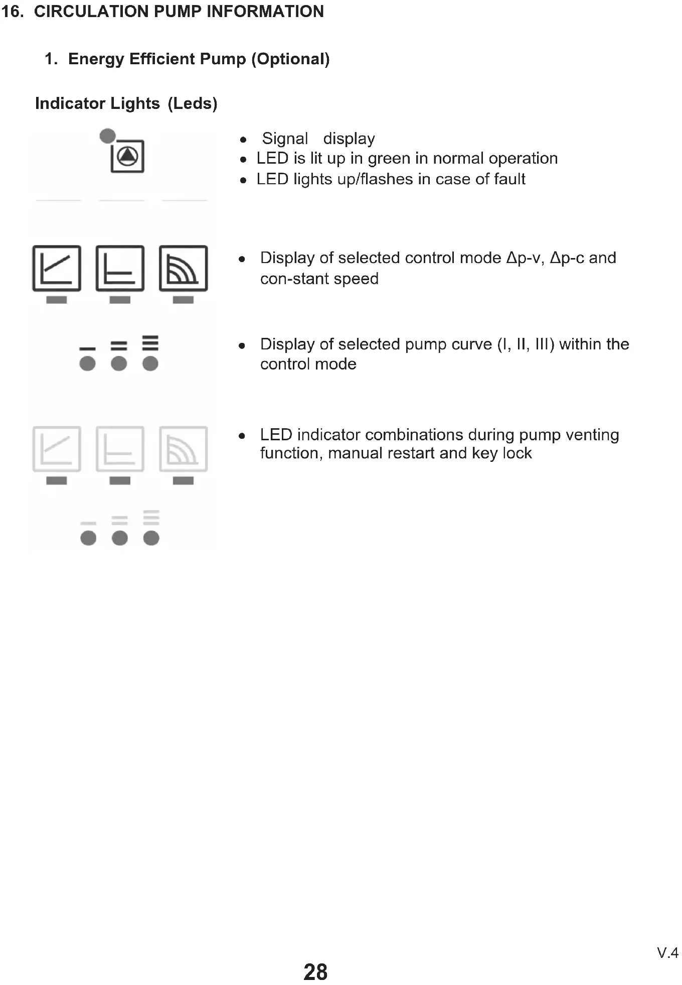
16. CIRCULATION PUMP INFORMATION
1. Energy Efficient Pump (Optional)
Indicator Lights (Leds)

text_image
Signal display LED is lit up in green in normal operation LED lights up/flashes in case of fault Display of selected control mode Δp-v, Δp-c and con-stant speed Display of selected pump curve (I, II, III) within the control mode LED indicator combinations during pump venting function, manual restart and key lockOperating button

natural_image
Pure electrical circuit lines without any symbolsPress
Select control mode
- Select pump curve (I, II, III) within the control mode Press and hold
- Activate the pump venting function (press for 3 seconds)
- Activate manual restart (press for 5 seconds)
- Lock/unlock button (press for 8 seconds)
Control modes and functions
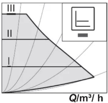
Variable differential pressure p-v (I, II, III)
H/m

text_image
III II I Q/m³/hConstant differential pressure p-c (I, II, III)
H/m
text_image
III II I Q/m³/ hRecommended for two-pipe heating systems with radiators to reduce the flow noise at thermostatic valves.
The pump reduces the delivery head to half in the case of decreasing volume flow in the pipe network.
Electrical energy saving by adjusting the delivery head to the volume flow requirement and lower flow rates. There are three pre-defined pump curves (I, II, III) to choose from.
Recommended for underfloor heating or for large-sized pipes, applications without a variable pipe network curve (e.g. storage charge pumps) or single-pipe heating systems with radiators.
The control keeps the set delivery head constant irrespective of the pumped volume flow.
There are three pre-defined pump curves (I, II, III) to choose from.
Constantspeed
(I, II, III)
H/m

text_image
III II IQ/m^3/h
Recommended for systems with fixed system resistance requiring a constant volume flow.
The pump runs in three prescribed fixed speed stages (I, II, III).
area
| Q/m³/h | H/m (Line I) | H/m (Line II) | H/m (Line III) | p/kPa (Line max) | |--------|--------------|---------------|----------------|------------------| | 0.0 | 0.0 | 0.0 | 3.0 | 0.0 | | 0.4 | 1.0 | 1.5 | 4.0 | 10.0 | | 0.8 | 2.0 | 2.5 | 6.0 | 30.0 | | 1.2 | 3.0 | 3.5 | 4.0 | 40.0 | | 1.6 | 4.0 | 4.5 | 3.0 | 50.0 | | 2.0 | 5.0 | 5.5 | 2.0 | 60.0 |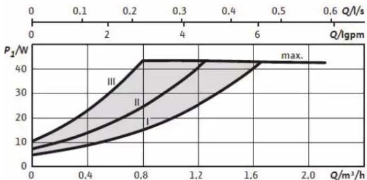
line
| Q/Igpm | P1/W (max.) | | ------ | ----------- | | 0.0 | 10 | | 0.4 | 20 | | 0.8 | 40 | | 1.2 | 40 | | 1.6 | 40 | | 2.0 | 40 |
natural_image
Black electronic device with green control panel and three monitors displaying icons (no text or symbols)
line
| Pressure | Flow Rate (q/m³/h) | Power (p/kPa) | |-----------|---------------------|---------------| | 15/6 | 0.8 | 60 | | 15/6 | 2.0 | 40 | | 15/6 | 2.0 | 20 | | 15/6 | 2.0 | 10 | | 20/6 | 0.8 | 60 | | 20/6 | 2.0 | 40 | | 20/6 | 2.0 | 20 | | 20/6 | 2.0 | 10 | | 25/6 | 0.8 | 60 | | 25/6 | 2.0 | 40 | | 25/6 | 2.0 | 20 | | 25/6 | 2.0 | 10 |
natural_image
Black rectangular device with green control panel and three icons representing computer, radio, and signal processing (no text or symbols)

natural_image
Black rectangular device with green control panel and three monitors displaying icons (no text or symbols)17. GUARANTEE CONDITIONS
This guarantee is for 2 years, starting from the date of purchase appearing in the user's invoice. In order for this guarantee to be valid, a mandatory start up and yearly maintenance must be performed by preferably the official Eas Electric technical service, or a service authorized by the local authorities in the matter.
Attention: The selection of the area where the boiler is installed must be in conformity with all relevant directives and laws of the country. Producer cannot be held responsible for any negative repercussions as a result of non compliance.
GUARANTEE EXCLUSIONS
- Devices used improperly, in a manner not in accordance with the instructions for use.
- Maintenance or servicing of the appliance: gas loads, periodic checks, adjustments, greasing and remote controls.
- Appliances disassembled or handled by persons other than authorised Technical Services.
- Materials broken or deteriorated due to wear and tear or normal use of the appliance: gaskets, plastics, filters, etc.
- Appliances that do not have the factory serial number identified or that have been altered or deleted.
- Breakdowns caused by unforeseen circumstances, force majeure or incorrect installation.
- Loss or damage to software or data carriers.
- Failures caused by external factors such as current alterations or inadequate power supply.
- Installation defects, such as lack of grounding connection between indoor and outdoor units, lack of grounding in the house, alteration of the order of phases and neutral, flaring in poor condition or connection with cooling pipes of different diameter.
- When there is pre-installation, damage caused by not carrying out an adequate previous cleaning of the installation with nitrogen and checking of watertightness.
- The linking of external devices, this may never lead to a change of unit (such as Wi-Fi connections).
- Replacement and/or repair of equipment/devices installed or located at a height of 2.20 meters or more above the ground.
-
Guarantee coverage does not cover freezing damage to plate and/or tube evaporators and water-cooled condensers.
-
The guarantee does not cover fuses, bands, bulbs, flow switches, filters and other elements whose normal wear and tear due to the operation of the equipment will be damaged.
- Do not add any chemicals to the closed heating circuit.
- The guarantee does not cover damage caused by weather conditions and/or earthquakes, floods, etc. Accidents, fires, liquids, chemicals, other substances, vibrations, excessive heat, inadequate ventilation, electrical overloads, excessive or incorrect voltage or supply, radiation, electrostatic discharges including lightning, and any external forces like insects, rodents or animals that might reach the interior of the appliance or its connection points.
- The assembling of non authentic and non approved parts to the boiler.
- Over heat or frost conditions of the area where the boiler is installed.
- Damages that occur as a result of inappropriate storing as showroom items for a long time.
- Parts that belong the boilers which are damaged during transportation.
- Damages that occur as a result of bad/dirty fuel use, the use of extremely calcerous water in hot water system (ideal water hardness must be 15-20 French hardness).
- Damages that occur as a result of low chimney draft.
- Unavailability of the documents that the authorised service issues after the first operation. The user must keep these documents at all times.
- For boilers that operate with LPG, damages that might occur when liquid phase fuel is consumed by the boiler as a result of transportation of the LPG tubes or tubes that are subject to over heat.
Design and specifications are subject to change without notice for product improvement.
EAS ELECTRIC
SMART TECHNOLOGY
www.easelectric.es
CONTENU
Página
1. PRÉCAUTIONS 2
1.1 SYMBOLES 2
1.2 AVIS GÉNÉRAUX
3
1.3 EXPLICATIONS GÉNÉRALES
2. INTRODUCTION À L'APPAREIL
2.1 ASPECTS ET DIMENSIONS EXTERNES
2.2 STRUCTURE INTERNE ET LISTE DES COMPOSANTS
2.3 PANNEAU DE CONTRÔLE 6
3. DÉTAILS DE L'INSTALLATION 7
3.1 CONNEXIONS ÉLECTRIQUES 9
3.2 OUVERTURE DE LA BOÎTE 9
3.3 MONTAGE MURAL 9
3.4 POINTS À PRENDRE EN COMPTE POUR L'INSTALLATION 10
3.5 ESPACES À RESPECTER POUR L'INSTALLATION 10
3.6 CONNEXION POUR LA VIDANGE DES CONDENSATS 11
3.7 SCHÉMA DE CONNEXION DE L'INSTALLATION 12
3.8 CONNEXIONS D'INSTALLATION 13
3.9 RACCORDEMENT DE LA CHEMINÉE 13
4. REMPLIR LE SYSTÈME ET VÉRIFIER LA PRESSION DE L'EAU 15
5. MISE EN SERVICE 15
5.1 VÉRIFICATIONS AVANT LE DÉMARRAGE 15
5.2 DÉMARRAGE DES OPÉRATIONS 16
5.3 COURBE DE PRESSION DE LA POMPE DE CIRCULATION 17
6. UTILISATION DE LA CHAUDIÈRE 18
7. SCHÉMA DE CONNEXION ÉLECTRIQUE 20
8. SYSTÈME DE SÉCURITÉ ET DÉPANNAGE 21
8.1 SANS COMBUSTION 22
8.2 PRESSION D'EAU BASSE-HAUTE 22
8.3 LIMITE DE SURCHAUFFE DU THERMOSTAT 22
8.4 SYSTÈME ANTI-CALCAIRE 23
9. RÉGLAGE DE LA PRESSION DE GAZ 23
- NETTOYAGE ET ENTRETIEN 23
- INFORMATION IMPORTANTE POUR VOTRE SECURITÉ 24
- UTILISATION EFFICACE DES CHAUDIÈRES EN FONCTION DE LA CONSOMMATION D'ÉNERGIE
- POINTS À PRENDRE EN COMPTE LORS DU TRANSPORT 26
- UTILISATION AVEC GPL
- ANNEXE : SPÉCIFICATIONS 27
- ANNEXE : POMPE DE CIRCULATION 20
- CONDITIONS DE GARANTIE 32
text_image
Technical diagram of an electrical enclosure with numbered components for identification
text_image
Technical diagram of an industrial machine with numbered components labeled 26, 27, and 28text_image
Diagram of a circular device with labeled components and directional arrows indicating flow or movement.natural_image
Pure technical line drawing of a mechanical component without any text, numbers, or symbolsSystème
natural_image
Pure electrical circuit lines without any symbolsChaudière
3.2 DÉBALLAGE

text_image
Diagram of a cardboard box with scissors and numbered label 1, likely for instructional or labeling purposes.
text_image
②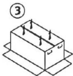
natural_image
Isometric line drawing of a rectangular box with internal arrows, placed on a flat base (no text or symbols)text_image
Technical diagram of a mechanical assembly with numbered components for identification
natural_image
Technical line drawing of a mechanical assembly with pipe and housing (no text or symbols)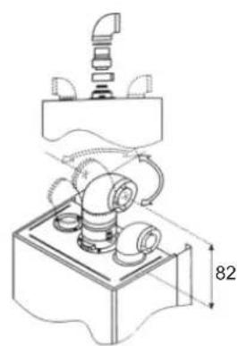
natural_image
Technical line drawing of a mechanical assembly with no visible text or symbolsnatural_image
Line drawing of a hand pouring liquid into a tray with three circular chambers (no text or symbols)8.1 PAS DE COMBUSTION, FAUSSE FLAMME
natural_image
Symbol of a trash bin crossed with diagonal lines, no text or numbers presentnatural_image
Abstract icon set with monitor, pie chart, and circular symbol (no text or labels)Appuyer
natural_image
Black electronic device with green control panel and three icons (no text or symbols)
line
| Q/m³/h | H/m (I) | H/m (II) | H/m (III) | p/kPa (max) | |--------|---------|----------|-----------|-------------| | 0.0 | 0 | 0 | 0 | 0 | | 0.4 | 0 | 0 | 6 | 60 | | 0.8 | 0 | 4 | 6 | 60 | | 1.2 | 0 | 4 | 4 | 40 | | 1.6 | 0 | 4 | 2 | 30 | | 2.0 | 1 | 4 | 1 | 10 |
natural_image
Black rectangular device with green circular indicator and three white icons on screen (no text or symbols)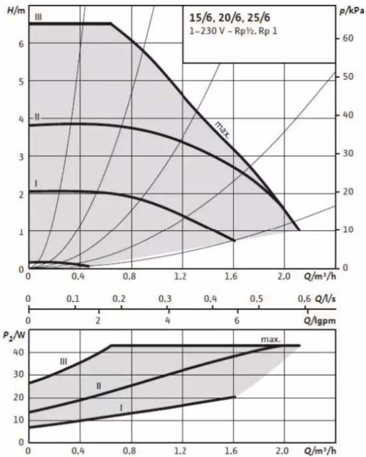

natural_image
Black square electronic device with three monitors and control buttons (no text or symbols)17. CONDITIONS DE GARANTIE
EXCLUSIONS DE LA GARANTIE
text_image
Technical diagram of an internal device with numbered components for identification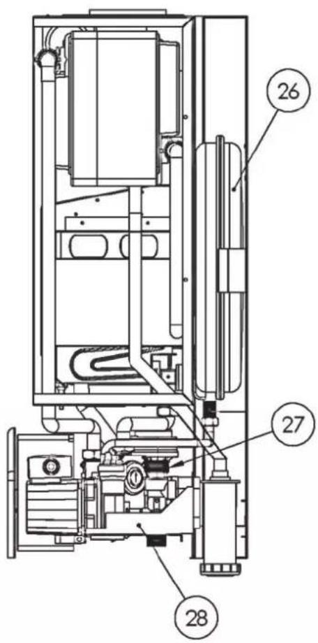
text_image
Technical diagram of an industrial machine with numbered components labeled 26, 27, and 28.text_image
Diagram of a circular device with labeled components and directional arrows indicating flow or movement.natural_image
Pure technical line drawing of a mechanical or electrical component without any text, numbers, or symbols
natural_image
Pure electrical circuit lines without any symbolsSistema
Caldeira
3.2 DESEMBALAGEM

text_image
1
natural_image
Simple line drawing of an open box with internal compartments and arrows indicating movement (no text or symbols)
natural_image
Isometric diagram of a rectangular box with internal arrows, placed on a flat base (no text or symbols)text_image
Technical diagram of a soldering iron with numbered components for assembly or maintenance reference.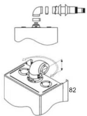
natural_image
Technical line drawing of a mechanical assembly with pipe and housing components (no text or symbols)
natural_image
Technical line drawing of a mechanical assembly with no visible text or symbols- Cotovelo do tubo
2.Junta de tubo extra - Clips de 37mm
4.Chaminé
5.Arruela de mola
natural_image
Line drawing of a hand pouring liquid into a tray with three circular chambers (no text or symbols)line
| p [kPa] | Q [m³/h] | H [m] | | ------- | -------- | ----- | | 0 | 0.0 | 35 | | 0 | 0.5 | 30 | | 0 | 1.0 | 25 | | 0 | 1.5 | 20 | | 0 | 2.0 | 15 | | 0 | 2.5 | 10 | | 0 | 3.0 | 5 | | 0 | 3.5 | 0 |TM00 9749 0397
8.1 SEM COMBUSTÃO, FALSA CHAMA
natural_image
Symbol of a trash bin crossed with a diagonal line and a horizontal bar below (no text or labels)natural_image
Pure electrical circuit lines without any symbolsnatural_image
Black electronic device with green control panel and three icons (no text or symbols)
line
| Q/m³/h | H/m (I) | H/m (II) | H/m (III) | p/kPa (max) | |--------|---------|----------|-----------|-------------| | 0.0 | 0 | 0 | 0 | 0 | | 0.4 | 0 | 0 | 6 | 60 | | 0.8 | 0 | 4 | 6 | 60 | | 1.2 | 0 | 4 | 4 | 40 | | 1.6 | 0 | 4 | 2 | 30 | | 2.0 | 1 | 4 | 1 | 10 |
natural_image
Black rectangular device with green circular indicator and three white icons on the right (no text or symbols)
line
| Q/m³/h | H/m (I) | H/m (II) | H/m (III) | p/kPa (max) | P₂/W (I) | P₂/W (II) | P₂/W (III) | |--------|---------|----------|-----------|------------|----------|-----------|------------| | 0.0 | 0.0 | 0.0 | 0.0 | 0.0 | 5.0 | 10.0 | 25.0 | | 0.4 | 0.0 | 0.0 | 6.5 | 60.0 | 10.0 | 20.0 | 35.0 | | 0.8 | 2.0 | 4.0 | 6.5 | 50.0 | 15.0 | 25.0 | 40.0 | | 1.2 | 1.5 | 3.5 | 5.5 | 40.0 | 20.0 | 30.0 | 45.0 | | 1.6 | 1.0 | 3.0 | 4.5 | 30.0 | 25.0 | 35.0 | 50.0 | | 2.0 | 1.0 | 2.5 | 3.5 | 20.0 | 30.0 | 40.0 | 55.0 | | 2.4 | 1.0 | 2.0 | 2.5 | 15.0 | 35.0 | 45.0 | 60.0 | | 2.8 | 1.0 | 1.5 | 1.5 | 10.0 | 40.0 | 50.0 | 65.0 | | 3.2 | 1.0 | 1.0 | 1.0 | 5.0 | 45.0 | 55.0 | 70.0 | | 3.6 | 1.0 | 1.0 | 1.0 | 2.5 | 50.0 | 60.0 | 75.0 | | 4.0 | 1.0 | 1.0 | 1.0 | 1.0 | 55.0 | 65.0 | 80.0 | | 4.4 | 1.0 | 1.0 | 1.0 | 0.5 | 60.0 | 70.0 | 85.0 | | 4.8 | 1.0 | 1.0 | 1.0 | 0.2 | 65.0 | 75.0 | 90.0 | | 5.2 | 1.0 | 1.0 | 1.0 | 0.1 | 70.0 | 80.0 | 95.0 | | 5.6 | 1.0 | 1.0 | 1.0 | 0.1 | 75.0 | 85.0 | 100.0 | | 6.0 | 1.0 | 1.0 | 1.0 | 0.1 | 80.0 | 90.0 | 105.0 | | 6.4 | 1.0 | 1.0 | 1.0 | 0.1 | 85.0 | 95.0 | 110.0 | | 6.8 | 1.0 | 1.0 | 1.0 | 0.1 | 90.0 | 100.0 | 115.0 | | 7.2 | 1.0 | 1.0 | 1.0 | 0.1 | 95.0 | 105.0 | 120.0 | | 7.6 | 1.0 | 1.0 | 1.0 | 0.1 | 100.0 | 110.0 | 125.0 | | 8.0 | 1.0 | 1.0 | 1.0 | 0.1 | 105.0 | 115.0 | 130.0 | | 8.4 | 1.0 | 1.0 | 1.0 | 0.1 | 110.0 | 120.0 | 135.0 | | 8.8 | 1.0 | 1.0 | 1.0 | 0.1 | 115.0 | 125.0 | 140.0 | | 9.2 | 1.0 | 1.0 | 1.0 | 0.1 | 120.0 | 130.0 | 145.0 | | 9.6 | 1.0 | 1.0 | 1.0 | 0.1 | 125.0 | 135.0 | 150.0 | | 10.0 | 1.0 | 1.0 | 1.0 | 0.1 | 130.0 | 140.0 | 155.0 | | >16 | <2 | <2 | <2 | <2 | <25% | <25% | <25% | The chart displays two panels: the top panel shows pressure (p/kPa) versus flow rate (Q/m³/h), and the bottom panel shows power (P₂/W). The x-axis represents flow rate in Q/gpm and the y-axis represents power in P₂/W for each panel type (I, II, III). Legend indicates different series of pressure and power values.
natural_image
Black square electronic device with icons for monitor, keyboard, and control buttons (no text or symbols)17. CONDIÇÕES DE GARANTIA
Scan for manual in other languages and further updates: