ECA 100 ipro VZC - Fan Maico - Free user manual and instructions
Find the device manual for free ECA 100 ipro VZC Maico in PDF.
| Product type | Extraction fan for small rooms |
| Brand | Maico |
| Model | ECA 100 ipro VZC |
| Nominal diameter | 100 mm |
| Required hole diameter | 105 mm minimum |
| Supply voltage | 230 V ~ 50 Hz |
| Power consumption | Approximately 20 W (not specified) |
| Speed levels | 2 |
| Airflow level 1 | 78 m³/h |
| Airflow level 2 | 92 m³/h |
| Adjustable start delay | 0 / 50 / 90 / 120 seconds |
| Adjustable run-on time | 0 / 8 / 17 / 25 minutes |
| Control programs | 4 (Comfort, Night, Economy, Power) |
| Built-in sensors | None (VZC version with timer) |
| Maximum fluid temperature | +40 °C |
| Mounting | Wall or ceiling |
| Maintenance | No maintenance required |
| Cleaning | Covers washable with water, interior with dry cloth |
| Safety | Thermal protection, automatic shutdown on overheating |
| Repairability | Repairs only by qualified electrician |
| Mains cable | 5 x 1.5 mm² (NYM-O or NYM-J) |
| Included accessories | Protective cover, design cover, foam strip |
Frequently Asked Questions - ECA 100 ipro VZC Maico
User questions about ECA 100 ipro VZC Maico
0 question about this device. Answer the ones you know or ask your own.
Ask a new question about this device
Download the instructions for your Fan in PDF format for free! Find your manual ECA 100 ipro VZC - Maico and take your electronic device back in hand. On this page are published all the documents necessary for the use of your device. ECA 100 ipro VZC by Maico.
USER MANUAL ECA 100 ipro VZC Maico
UK Mounting and Operating instructions Small room fans
natural_image
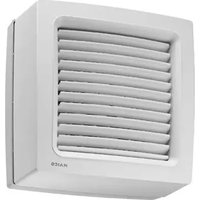
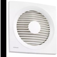
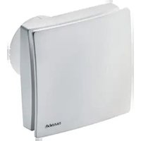
White rectangular electronic device with a circular top and side panel, no visible text or symbols on the body.ECA 100 ipro VZC
ECA 100 ipro F
ECA 100 ipro H
ECA 100 ipro B
ECA 100 ipro K
ECA 100 ipro KVZC
ECA 100 ipro KF
ECA 100 ipro KH
ECA 100 ipro KB
- Small room fan ECA 100 ipro
- Electronics cover
- Sensor (only for models F, H and B)
- Foam strip
• Installation and operating instructions
Éléments fournis
text_image
QR code image containing encoded data, no visible human-readable texttext_image
Technical diagram of a device with labeled parts and internal components, showing numbered parts 6 and 7.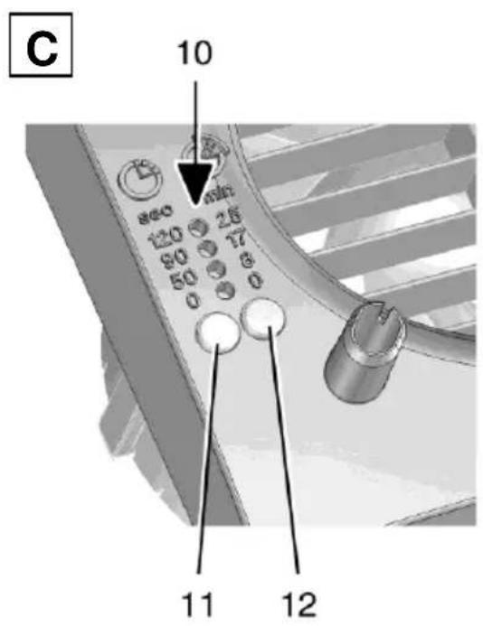
1.1 Installationspersonal....2
1.2 Verwendete Symbole ...... 2
- Produktinformationen .... 3
1.1 Installationspersonal
natural_image
3D model of a beige rectangular electronic device with labeled components (no readable text or symbols)natural_image
3D rendering of a mechanical component with cutaway view showing internal structure (no text or symbols)text_image
II Made in Germany PRESS III 12 11 Inatural_image
3D rendered image of a gray rectangular electronic device with an arrow pointing to its side (no text or symbols on the device itself)- General advice.... 12
1.1 Installation staff .... 12
1.2 Symbols used.... 12
- Product information 13
2.1 Unit overview.... 13
2.2 Product description ...... 13
2.3 Intended use .... 14
2.4 Predictable misuses .... 14
-
Environmental conditions and operating limits....14
-
Technical data.... 14
-
Safety instructions.... 15
5.1 General 15
5.2 Safe and correct practices during operation....15
5.3 Supply air intake within the living area.... 15
- Installation preparations .... 16
6.1 Wall 16
6.2 Ceiling 16
6.3 Duct.... 16
6.4 Fan....16
- Installation.... 17
7.1 Installing housing 17
7.2 Electrical connection ...... 17
7.3 Operating programs .... 18
7.4 Start-up 19
7.5 Start delay and overrun time ..... 19
-
Maintenance.... 19
-
Cleaning....20
-
Fault rectification 20
-
Dismantling 21
-
Disposal 21
-
Wiring diagrams ...... 33
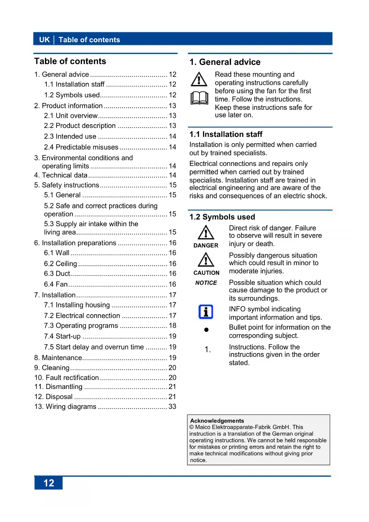
1. General advice


Read these mounting and operating instructions carefully before using the fan for the first time. Follow the instructions.
Keep these instructions safe for use later on.
1.1 Installation staff
Installation is only permitted when carried out by trained specialists.
Electrical connections and repairs only permitted when carried out by trained specialists. Installation staff are trained in electrical engineering and are aware of the risks and consequences of an electric shock.
1.2 Symbols used

DANGER
Direct risk of danger. Failure to observe will result in severe injury or death.

CAUTION
Possibly dangerous situation which could result in minor to moderate injuries.
NOTICE
Possible situation which could cause damage to the product or its surroundings.


1.
INFO symbol indicating important information and tips.
Bullet point for information on the corresponding subject.
Instructions. Follow the instructions given in the order stated.
Acknowledgements
© Maico Elektroapparate-Fabrik GmbH. This instruction is a translation of the German original operating instructions. We cannot be held responsible for mistakes or printing errors and retain the right to make technical modifications without giving prior notice.
2. Product information
2.1 Unit overview, Fig. A, B and C
1 Housing with motor
2 Impeller
3 Cable grommet
4 Electronics cover
5 Internal grille or internal shutter
5.1 Fixed internal grille
5.2 Electrically operated internal shutter
5.3 Bimetal
6 Cover
7 Designer cover
8 Electronic circuit boards
8.1 Standard electronics
8.2 Sensor electronics (only for models F, H and B)
8.3 VZC electronics
9 Sensors
9.1 Motion sensor "B"
9.2 Light sensor "F"
9.3 Humidity sensor "H"
10 Start delay/overrun time for LEDs
11 Start delay setting button
12 Overrun time setting button
2.2 Product description
- Small room fan for extracting air from rooms.
• ECA 100 ipro with fixed internal grille. - ECA 100 ipro K with electrically operated internal shutter.
- Two performance levels as standard.
- Models
Standard: Can be operated at two levels with an optional double switch.
VZC and KVZC: Model with start delay and overrun time.
F and KF: Model with light sensor, start delay and overrun time. Switch-on intensity (at fan) min. 30 lux. Switch-off intensity (at fan) max. 1.7 lux.
H and KH: Model with humidity control (fully automatic), start delay and overrun time.
B and KB: Model with motion detector and overrun time. Without start delay. Monitoring range of motion detector horizontal 100°/vertical 82°.
| Unit model | Start delay [sec.] | Overrun time [min.] | Mains cable [mm2] | 4 operating programmes | Speed controllable |
| ECA 100 ipro | 5 x 1,5 | ● | |||
| ECA 100 ipro VZC | 0/50/90/120 | 0/8/17/25 | 5 x 1,5 | ● | |
| ECA 100 ipro F | 0/50/90/120 | 0/8/17/25 | 3 x 1,5 | ● | |
| ECA 100 ipro H | 0/50/90/120* | 8/17/25** | 3 x 1,5 | ■ | |
| ECA 100 ipro B | 0/8/17/25 | 3 x 1,5 | ● | ||
| ECA 100 ipro K | 5 x 1,5 | ● | |||
| ECA 100 ipro KVZC | 0/50/90/120 | 0/8/17/25 | 5 x 1,5 | ● | |
| ECA 100 ipro KF | 0/50/90/120 | 0/8/17/25 | 3 x 1,5 | ● | |
| ECA 100 ipro KH | 0/50/90/120* | 8/17/25** | 3 x 1,5 | ■ | |
| ECA 100 ipro KB | 0/8/17/25 | 3 x 1,5 | ● |
Bold Condition as supplied
• Standard equipment
■ 4 operating programs available with optional light switch
* Start delay available when using an optional switch (e.g. light switch).
** 0 min overrun time available when using an optional switch (e.g. light switch).
UK | 2. Product information
Humidity control function for H and KH units
Once the fan is installed, it adjusts itself to the prevailing room humidity (relative humidity). This humidity value is saved as the first reference value. The reference value does not have to be specified manually.
If the relative humidity falls below the reference value during operation, the newly established reference value is saved. The lowest possible reference value is 48 % relative humidity.
If the room humidity increases by 7 %, the fan engages automatically at performance level 1 (78 m³/h).
- If the room humidity increases even further, the unit switches to performance level 2 (92 m³/h).
- If there are no further increases, the unit continues to run at performance level 1 until the humidity again falls below the saved reference value.
If the humidity falls below the reference value, overrun mode starts with the set overrun time. The current reference value is then saved. If the humidity does not fall below the reference value within 60 minutes, the unit switches to the set overrun mode and then switches off.

H and KH units can also be operated using the light switch. The set operating program starts when the light is switched on ( chapter 7.3). The operating program takes priority over the automatic humidity process. If the light is switched off, the unit continues to run until the remaining overrun time has passed. The automatic humidity process is then assigned maximum priority again and controls the unit as described above.
2.3 Intended use
- This fan is only intended for domestic use and similar purposes.
-
Fan for or extracting air from bathrooms, toilet rooms, storage rooms, showrooms, offices, fitness studios, changing rooms and similar places.
-
An operation is only permitted when:
• permanent installation in buildings. - installation on walls or ceilings.
• air supply via shaft or pipe.
• recessed mounted electrical connection.
- Window installation permitted with window installation kit FE 100/1, connection in flat channel duct systems permitted with spacing frame ECA-DR.
2.4 Predictable misuses
Maico is not liable for damages caused by use contrary to the intended purpose. Under no circumstances the unit should be used:
- in single air extraction systems according to DIN 18017-3.
- close to flammable materials, liquids or gases.
- for the conveying of chemicals, aggressive gases or vapours.
• in potentially explosive atmospheres - outdoors.
3. Environmental conditions and operating limits
- Maximum permitted temperature of the air medium + 40 °C.
- Sufficient supply air intake must be ensured during operation with air-ventilated fireplaces. The maximum permitted pressure difference per living unit is 4 Pa.
- Resistance to interference according to EN 55014-2 depending on pulse shape and energy component 1000 to 4000 V. If operating with fluorescent tubes, extra interference suppression measures are needed (L or C components or RC modules, protection diodes, varistors) because these values may be exceeded.
- Recommendation: Connect a X2-capacitor (220 nF/250 V) against neutral lead in case of a switch with negative-glow lamp. The capacitor is to be provided by the customer.
4. Technical data
See rating plate.
5. Safety instructions
5.1 General
- Assembly and electrical connection may only be undertaken by electricians in accordance with chapter 1.
- Read these operating instructions carefully before commissioning.
- Only connect unit to permanently wired electrical installations with NYM-O or NYM-J (3 x 1.5 mm ^2 or 5 x 1.5 mm ^2 ) cables. Fixture for disconnecting from mains, with at least 3 mm contact opening needed per pole.
- The fan unit may only be operated using the voltage and frequency shown on the rating plate.
- Do not make any modifications to the fan unit.
- Never operate unit without electronics cover [4] and cover [6].
5.2 Safe and correct practices during operation
Danger of injury caused by objects in the impeller. Do not insert any objects in the fan unit.
Danger of injury from rotating impeller. Do not get too close to the fan unit, to avoid hair, clothing or jewellery being drawn into the unit.
- Risks for people (including children) with reduced physical, sensory or mental capabilities or a lack of knowledge. Fan may only be installed, commissioned, cleaned and maintained by people who can safely recognise and avoid the risks associated with this work. Children must not play with the unit.
5.3 Supply air intake within the living area
- The domestic air supply must be set-up so that virtually no air can flow into the living areas from the kitchen, bathroom and WC.
- A room from which the air has to be extracted must be fitted with an non-closable, free supply air cross section of at least 150 ~cm^2 , e.g. with door ventilation grille MLK.
6. Installation preparations
6.1 Wall

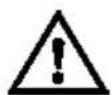
The prescribed minimum distances between the wall and the ceiling shown in the figure must be observed.
text_image
22 mm 105 mm 85 mm 61mm- Make sure the housing has a level base.
- Fit wall breakthrough or drill core hole. Minimum diameter, 105 mm.

Recommendation: Fit wall sleeve WH 100. Fit wall breakthrough with a minimum diameter of 115 mm.

Use mounting plate ZM 11 for rectangular wall breakthroughs.
- Lay power cable (recessed) up to place of installation, see above for spacing. Guide the power cable at least 110 mm from the wall.
6.2 Ceiling
NOTICE
Danger of short-circuits and damage to unit if condensation builds up in the fan housing.
Thermally insulate ventilation ducts in professional manner.
Allow for a condensation drain or condensate collector in the riser.
Perform installation preparations as described in Chapter 6.1.
6.3 Duct
- Debur edges on the inside of the duct.
- Perform installation preparations as described in Chapter 6.1.
6.4 Fan
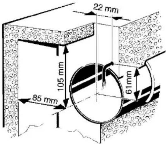
natural_image
3D model of a gray rectangular object with an arrow pointing to its base, labeled '6' and 'HAICO' (no other text or symbols)- Unpack ECA and remove cover [6]. Unlock locking hooks ( arrow) with screwdriver to loosen cover.
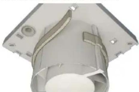
natural_image
3D rendering of a mechanical component with internal channels and mounting holes (no text or symbols visible)- Fit foam strip supplied to connector in centre.

The foam strip must be fitted to ECA 100 ipro H and KH such that the units do not draw in any unwanted air from outside.
7. Installation

For installation with window installation kit FE 100/1 or spacing frame ECA-DR → dedicated mounting instructions.
7.1 Installing housing
- Insert housing [1] into wall breakthrough/wall sleeve (TOP must be at top).
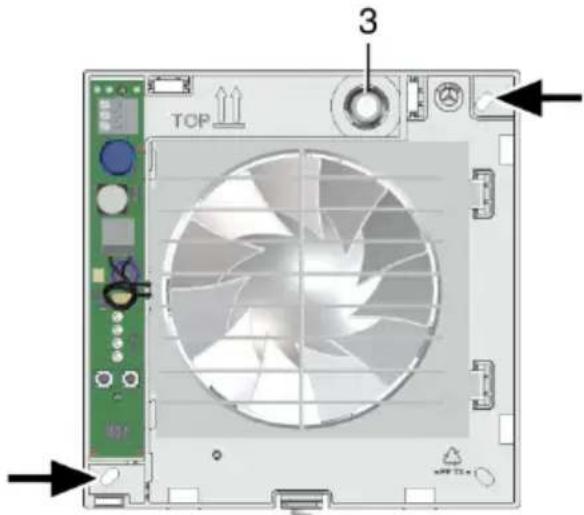
text_image
TOP 3- Align housing horizontally and mark the two dowel holes ( arrows).
- Remove housing [1], drill M6 dowel holes with a ∅ of 6 mm and insert dowels.
- Push cable grommet [3] carefully out of housing and remove.
NOTICE
Danger of short circuits and damage to unit! Water will penetrate if the power cable is incorrectly fed into the fan housing or if the cable grommet is not fitted correctly.
Cut off cable grommet cap [3] such that the cable grommet fits tightly round the power cable. Cut off at least 5 mm of the cap (power cable can bend better and electronics cover [4] can be positioned correctly).
Fit cable grommet [3] correctly, seal on both sides if required.
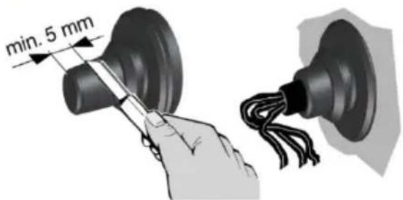
text_image
min. 5 mm- Insert cable grommet into housing.

Guide power cable into connection area such that the cable grommet fits around the cable sheathing completely and does not penetrate too far into the connection area.
7.2 Electrical connection

DANGER
Danger to life from electric shock.
Switch the mains fuse off.
NOTICE
Unit damage in the case of short-circuits.
Insulate PE conductor and unneeded cable cores.
- Only lay single cable cores in the unit. To do this, reduce power cable sheathing to a length of 100 ~mm . Strip single cable cores to 9 to 10 ~mm .
- Insert housing [1] into wall breakthrough/ wall sleeve and secure with two screws. Do not insert the housing such that it is twisted or crushed. Make sure you use mounting material which is sized for the purpose.
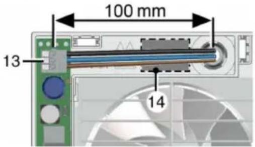
text_image
100 mm 13 14- Electrically connect power cable to spring clip [13] according to connection wiring diagram [14], also see wiring diagrams in Chapter 13.

ECA 100 ipro standard model units can be operated at two levels with double switches. Without a double switch, the fan can either be operated at performance level 1 or performance level 2, see switch variants in Chapter 13.
- Check position of cable grommet. It must be well sealed.
7.3 Operating programs
- VZC, KVZC, F, KF, B and KB: One of the 4 following operating programs can be set with jumpers J4 and J5.
- H and KH: One of the 4 following operating programs can be set with jumpers J4 and J5 and the light switch connected in accordance with chapter 13. If this is switched on, it takes priority over the automatic humidity process.
- Comfort program (supplied in this mode), night program, economy program and power program.
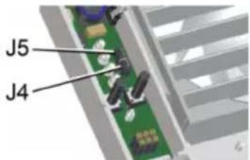
text_image
J5 J4- Set the operating program you want with jumpers J4 and J5.
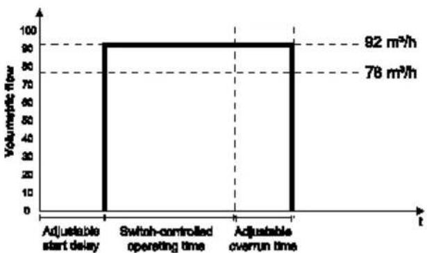
Comfort program
- Performance level 1 while room is being used, performance level 2 during overrun time.
• J4 bridged, J5 bridged
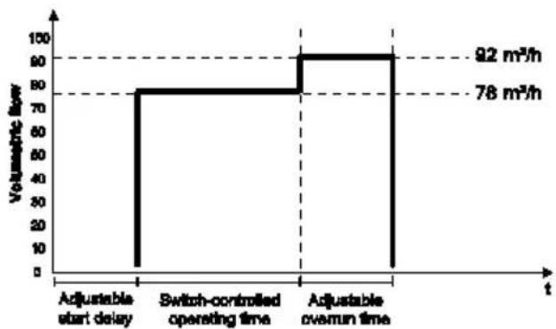
line
| t | Volumetric flow | | ------------------ | --------------- | | Adjustable start delay | 0 | | Switch-controlled operating time | 78 | | Adjustable overrun time | 92 |Night program
- Performance level 2 while room is being used, performance level 1 during overrun time.
- J4 open, J5 open
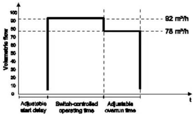
bar
| Time | Volumetric flow (m²/h) | |---|---| | Adjustable start delay | 0 | | Switch-controlled operating time | 92 | | Adjustable overrun time | 78 |Economy program
- Performance level 1 during operation and overrun.
• J4 open, J5 bridged
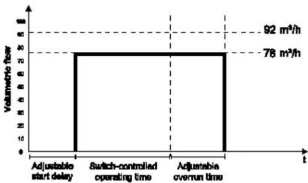
bar
| Time | Volumetric flow (m³/h) | |---|---| | Adjustable start delay | 0 | | Switch-controlled operating time | 30 | | Adjustable overrun time | 30 | | 92 | 78 | The chart displays a single vertical bar at the center of the interval, indicating that the volume is measured at each time point. The values for 'Adjustable start delay' and 'Switch-controlled operating time' are not explicitly labeled but visually represent the same magnitude of the bar height.Power program
- Performance level 2 during operation and overrun.
• J4 bridged, J5 open
bar
| Time Interval | Volumetric Flow | | :--- | :--- | | Adjustable start delay | 92 m³/h | | Switch-controlled operating time | 78 m³/h | | Adjustable overrun time | 92 m³/h |2. Fit electronics cover.
NOTICE
Danger of short circuits and damage to unit! Humidity will penetrate if electronics cover is not used correctly.
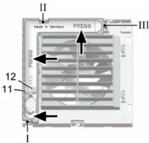
Press electronics cover firmly onto housing such that it is sealed and flush all the way around. Do not press setting buttons [11] and [12].
text_image
II Made in Germany PRESS III 12 11 I- Insert electronics cover into housing recesses I, II and III with the 3 latches until they snap into place. Press the electronics cover firmly on to the housing at the points indicated by the arrows.
text_image
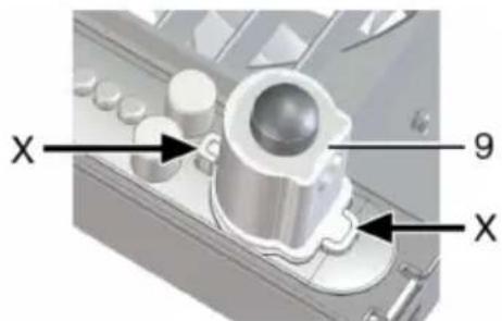
X 9 X- For unit versions F, KF, H, KH, B and KB, insert the sensor supplied [9] in the correct position ( arrow X) in the connector base.
- Fit cover [6].
- Set start delay and overrun time in accordance with Chapter 7.5.
- Fit designer cover [7] ( fold out page, Fig. B).
7.4 Start-up
- Switch the mains fuse on.
- Carry out a function test.
7.5 Start delay and overrun time

When the setting button is pressed for the first time, the value currently set is displayed. The LEDs are off during operation.

For condition in which unit is supplied, table in Chapter 2.1.
- Remove designer cover [7] carefully ( fold out page, Fig. B).
text_image
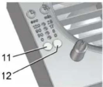
11 12- Set start delay:
Press setting button [11] until the LED for the start delay time you want lights up. Wait until the LED flashes twice and goes out. The value is now saved.
- Set overrun time:
Press setting button [12] until the LED for the overrun time you want lights up. Wait until the LED flashes twice and goes out. The value is now saved.

The settings take effect during the next switch process (sensor, light switch).
- Fit designer cover [7] ( fold out page, Fig. B).
8. Maintenance
The unit is maintenance-free.
9. Cleaning

DANGER
Danger to life from electric shock.
Switch the mains fuse off.
NOTICE
Damage to unit if incorrect cleaning agent is used.
Only clean cover [6] and designer cover [7] with water. Do not use aggressive cleaning agents.
NOTICE
For ECA 100 ipro K: lamella may break if cleaned incorrectly.
Take care when cleaning. Do not exercise force when opening, shutting or bending the lamella..
- Only clean inside parts of the fan with a dry cloth.
- If the designer cover [7] is very dirty, remove it carefully ( fold out page, Fig. B) and clean with water.
- Fit designer cover [7] ( fold out page, Fig. B).
- Call on the services of a trained electrician any time there is a fault.
- Repairs should only be carried out by a trained electrician.

DANGER
Danger to life from electric shock.
Switch off mains fuse before working on electrical connection.
| Fault | Cause, Measure |
| Fan does not switch on. | Start delay (max. 120 seconds).Wait for the start delay and reduce if necessary, → Chap. 7.5. |
| Fan does not switch on. | No mains voltage.Check whether the mains fuse has failed. Switch on if necessary. |
| Fan does not switch on. | Impeller blocked.Should only be carried out by a trained electrician: Remove cover [6]. Unlock internal grille [5.1] or internal shutter [5.2] using locking hooks (see arrow) and remove. Check impeller and clean if necessary. |
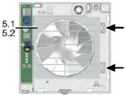
text_image
TOP 5.1 5.2| Fan does not switch off. | Overrun time (max. 25 minutes).Wait for the overrun time and reduce if necessary,→ Chapter 7.5. |
| Motor's thermal overload protection switches the fan off. | Motor too hot.Wait until the motor has cooled. Cool-down time can be up to 10 minutes. Unit switches back on automatically after cooling. |
| Lamella do not open or close for K units. | 1) Lamella very dirty or blocked.Clean lamella. Check whether there is any-thing between the lamella. Remove if necessary.2) Check whether the wiring is correctly carried out refer to diagram 1 (high level), page 33.Bridge terminal 1 and 2. |
Fault
Fan does not switch off or fan switch on accidentally.
Cause, Measure
A high-impedance voltage applies against terminal L1 with a control switch negative glow lamp, parallel installed wires (mutual induction) or transformers respectively other electrical parts.
Recommendation: Connect a X2-capacitor (220 nF/250 V) against neutral lead.
12. Disposal

Not in domestic waste. The unit contains in part material that can be recycled and in part substances that should not end up as domestic waste.
Dispose of the unit once it has reached the end of its working life according to the regulations valid where you are.
11. Dismantling

Dismantling may only be undertaken by an electrician.

DANGER
Danger to life from electric shock.
Switch off mains fuse before removing.

CAUTION
Danger of burning due to contact with bimetal (K units).
Bimetal [5.3] is very hot after fan is switched off. Do not touch. Cool-down time can be up to 10 minutes.
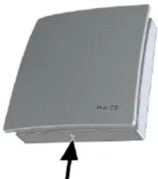
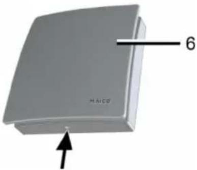
natural_image
3D rendered image of a gray rectangular object with an arrow pointing to its base (no text or symbols on the object itself)- Unlock covers (see arrow) and remove.
- Remove electronics cover [4] (3 latches).
- Remove power cable.
- Remove fan.
Sommaire
natural_image
3D model of a beige rectangular electronic device with labeled part 'HAICO' and number '6', showing no readable text or symbols beyond the label.natural_image
3D rendering of a mechanical component with cutaway view showing internal structure (no text or symbols)text_image
II Made in Germany PRESS III PRESS 12 11 Inatural_image
3D rendering of a gray rectangular electronic device with an arrow pointing to its side (no text or symbols on the device itself)text_image
L N S1 ① N 2 1 M 1 ~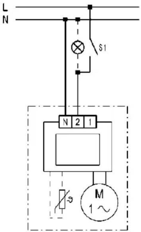
text_image
L N S1 N 2 1 M 1~① ECA 100 ipro K
text_image
L N L L N 2 1 M 1~ECA 100 ipro mit/with/avec ST1/STU1 ECA 100 ipro K mit/with/avec ST1/STU1
Drehzahl mit ST1/STU1 einstellbar Rotating speed, adjustable with ST 1/STU 1 Vitesse réglable avec ST1/STU1
text_image
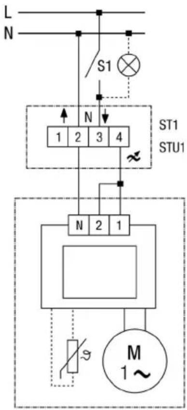
L N S1 N 1 2 3 4 ST1 STU1 N 2 1 M 1~ST1 Drehzahlsteller Aufputz Speed controller surface-mounted Régulateur de vitesse, installation apparent STU1 Drehzahlsteller Unterputz Speed controller recessed mounted Régulateur de vitesse, installation encastrée
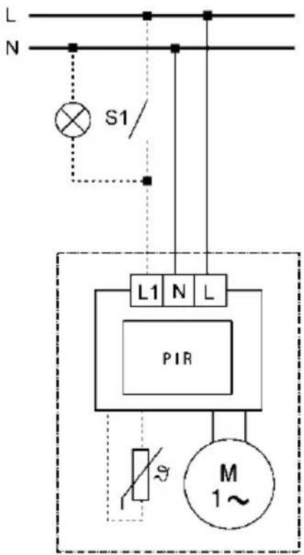
ECA 100 ipro VZC
ECA 100 ipro KVZC
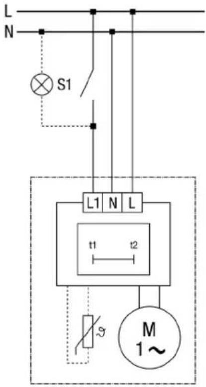
text_image
L N S1 L1 N L t1 t2 M 1~ECA 100 ipro F
ECA 100 ipro KF
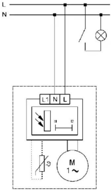
text_image
L N L1 N L u l2 M 1~ECA 100 ipro H
ECA 100 ipro KH
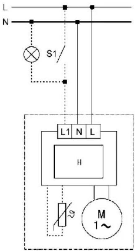
text_image
L N S1/ L1 N L H M 1~ECA 100 ipro B
ECA 100 ipro KB