ECA 120 P - Fan Maico - Free user manual and instructions
Find the device manual for free ECA 120 P Maico in PDF.
User questions about ECA 120 P Maico
0 question about this device. Answer the ones you know or ask your own.
Ask a new question about this device
Download the instructions for your Fan in PDF format for free! Find your manual ECA 120 P - Maico and take your electronic device back in hand. On this page are published all the documents necessary for the use of your device. ECA 120 P by Maico.
USER MANUAL ECA 120 P Maico
UK Mounting and Operating instructions Small room fans
natural_image
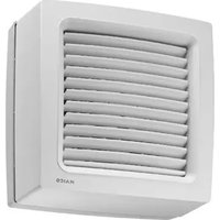
White industrial air vent fan with ventilation slots and a black label 'MAICO' (no additional text or symbols visible)ECA 120 K
| Montage- und BetriebsanleitungSeite 2 | Mounting an Operating instructionsPage 9 | Instructions de montage et Mode d'emploiPage 16 |
| SchaltbilderSeite 24 | Wiring diagramsPage 24 | Schémas de branchementPage 24 |
| Lieferumfang• KleinraumventilatorECA 120 oder ECA 120 K• Montage- und Betriebsanleitung | Scope of delivery• Small room fanECA 120 or ECA 120 K• Mounting and operating instructions | Éléments fournis• Aérateur pour petites pièces ECA 120 ou ECA 120 K• Instructions de montage et d'utilisation |
text_image
QR code image containing encoded data, no visible human-readable texttext_image
A AP UP 40 mm 100 mm 71 mm 100 mm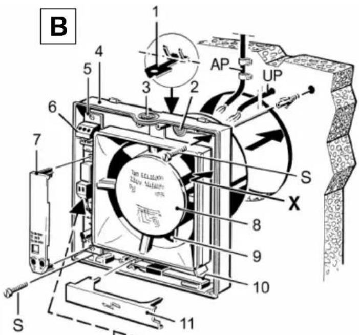
text_image
B 1 2 3 4 5 6 7 S AP UP S X 8 9 10 11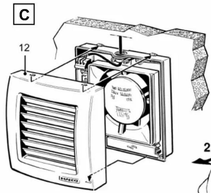
text_image
C 12 HACO 700 LECALON 350V MELON HPA 2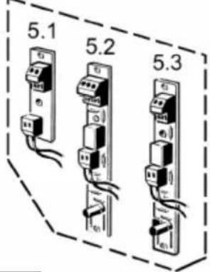
text_image
5.1 5.2 5.3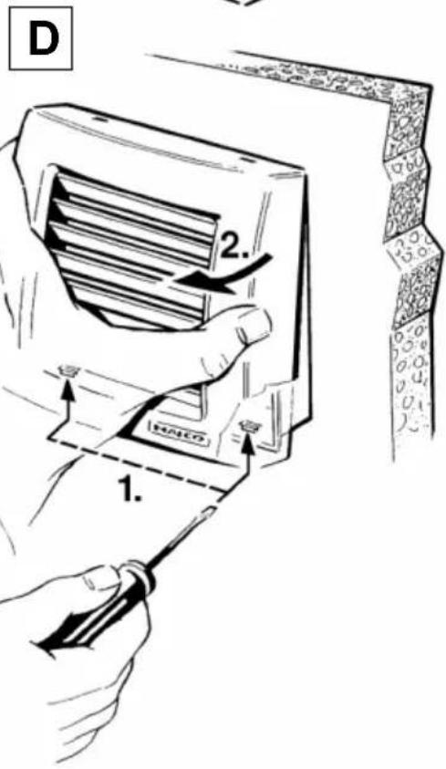
text_image
D 1. 2.Inhaltsverzeichnis
1.1 Installationspersonal
text_image
UP AP 13 13- General notes ...... 9
1.1 Installation staff 9
1.2 Symbols used 9
- Product information.... 10
2.1 Unit overview 10
2.2 Product description 10
2.3 Intended use 10
2.4 Foreseeable cases of misuse.... 11
-
Environmental conditions and operating limits.... 11
-
Technical data.... 11
-
Safety instructions.... 11
5.1 General 11
5.2 Safe and correct practices during operation.... 12
- Installation preparations.... 12
6.1 Wall.... 12
6.2 Ceiling.... 12
6.3 Duct 13
6.4 Fan.... 13
- Installation.... 13
7.1 Installing housing 13
7.2 Electrical connection 13
7.3 Commissioning 14
-
Maintenance 14
-
Cleaning.... 14
-
Fault rectification.... 14
-
Spare parts ...... 15
-
Dismantling 15
-
Disposal 15
-
Wiring diagrams 24
Acknowledgements:
© Maico Elektroapparate-Fabrik GmbH. English translation from the original German Operating Instructions. We cannot be held responsible for mistakes or printing errors and retain the right to make technical modifications without giving prior notice.
1. General notes


Read these mounting and operating instructions carefully before using the fan for the first time. Follow the instructions. Keep these instructions safe for use later on.
1.1 Installation staff
Installation is only permitted when carried out by trained specialists.
Only qualified electricians are permitted to make the electrical connections. Installation staff are trained in electrical engineering and are aware of the risks and consequences of an electric shock.
1.2 Symbols used

DANGER
Direct risk of danger. Failure to observe will result in severe injury or death.

CAUTION
Possibly dangerous situation which could result in minor to moderate injuries.
NOTICE
Possible situation which could cause damage to the product or its surroundings.

●
INFO symbol indicating important information and tips.
Bullet point for information on the corresponding subject.
1.
Instructions. Follow the instructions given in the order stated.
2. Product information
2.1 Unit overview, Fig. A, B and C
1 Spring hook
2 Cable grommet, rear
3 Cable grommet, top
4 Housing with motor
5 Electronic circuit board
5.1 Mother board (Standard, P, 24-V)
5.2 VZ circuit board
5.3 F circuit board
6 Terminal block
7 Electronics cover (VZ, KVZ, F, KF)
8 Motor protection cover
9 Impeller
10 ECA 120 K: Thermostatic bimetal strip
11 ECA 120 K: Bimetal cover
12 Internal grille / shutter frame
S Screw (not included in scope of delivery)
2.2 Product description
• ECA 120 with fixed internal grille.
- ECA 120 with electrically operated shutter frame.
Models
- Standard model: Can be operated with switch which is to be provided by the customer. Unit, speed controllable.
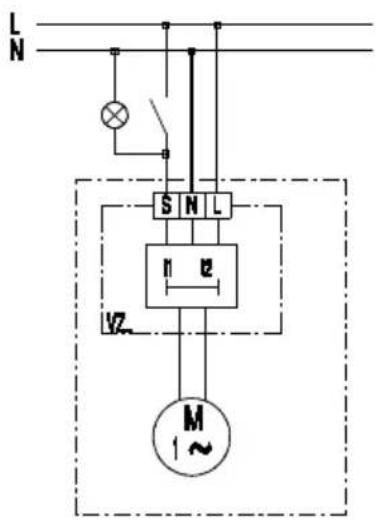
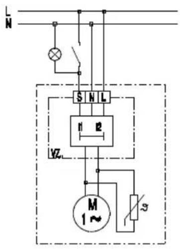
- Model VZ with time delay switch. Can be operated with switch which is to be provided by the customer. Adjustable start delay approx. 50 seconds and overrun time approx. 6 minutes. Unit, not speed controllable.
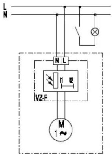
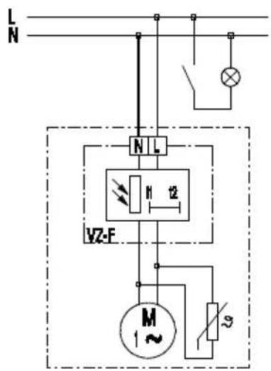
- Model F with light control, adjustable start delay approx. 50 seconds and overrun time approx. 6 minutes. Barrier-free application. The light control switches the fan automatically on and off: Switch-on intensity at fan min. 30 lx, switch-off intensity at fan max. 0.3 lx. Unit, not speed controllable.
F units can be operated independently of the lighting using the optional light switch. The automatic operating mode commences when "Light on". If the light is switched off, the unit continues to run until the remaining overrun time has passed.
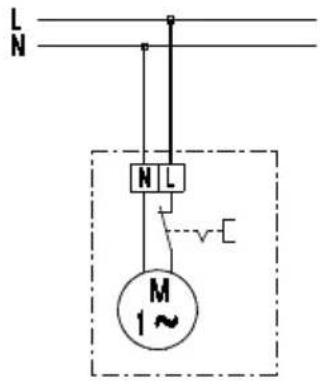
- Model P: With pull-cord switch. Unit, not speed controllable.
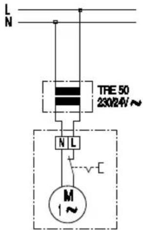
- 24 V model with safety extra-low voltage 24 V, 50 Hz. Can be operated with optional switch. Can be combined with time delay switch VZ 6, VZ 12 or VZ 24 C (see accessories). Unit, not speed controllable.
2.3 Intended use
- ECA 120 and ECA 120 K are small room fans for extracting air from rooms.
- These fan units are only intended for domestic use and similar purposes.
- The fan units are used to extract air from bathrooms, WCs, storage rooms, cellars, single family-unit houses, offices and similar places.
• Operation is only permitted when:
- fixed installation within buildings.
- surface installation on walls, ceilings or ducts.
• air supply via shaft or duct. - permanent electrical connection, surface-mounted or recessed-mounted.
- with sufficient space from the wall or ceiling as shown in Fig. A.
- unit is completely installed.
- The operation of the 24 V model is only permitted with approved safety isolating transformer TRE 50 (230 V/24 V). The time delay switches are to be installed between switch (230 V) and input side of the safety isolating transformer in accordance with the wiring diagram.
2.4 Foreseeable cases of misuse
Maico is not liable for damages caused by usage other than its intended purpose. The fan unit should not be used:
- in single air extraction systems according to DIN 18017-3.
- close to flammable materials, liquids or gases.
- to convey chemicals, aggressive gases or vapours.
• in potentially explosive atmospheres. - outdoors
- if there is no protection against accidental contact with the impeller on the discharge side in accordance with EN ISO 13857.
3. Environmental conditions and operating limits
- Permissible maximum temperature of air medium + 40 °C.
- The domestic air supply must be set up so that virtually no air can flow into the living areas from the kitchen, bathroom and WC.
- A room from which the air has to be extracted must be fitted with a non-closable, free supply air cross section of at least 150 cm ^2 , e.g. with Maico door ventilation grille MLK.
- Sufficient supply air intake must be ensured during operation with air-ventilated fireplaces. The maximum permitted pressure difference per living unit is 4 Pa.
- VZ, F, KVZ and KF units: Resistance to interference according to EN 55014-2 depending on pulse shape and energy component 1000 to 4000 V. If operating with fluorescent tubes, extra interference suppression measures are needed (L or C components or RC modules, protection diodes, varistors) because these values may be exceeded.
4. Technical data
See rating plate.
5. Safety instructions
5.1 General
- Read these operating instructions carefully before mounting and commissioning.
- Assembly and electrical connection may only be undertaken by trained specialists in accordance with Chapter 1.
- With electrical and equipment installation the relevant regulations must be observed, in Germany particularly DIN VDE 0100 with the corresponding parts.
- Only connect unit to permanently wired electrical installations with NYM-O or NYM-J (2 x 1.5 mm ^2 or 3 x 1.5 mm ^2 ) cables. Mains isolation device required with contact openings of at least 3 mm at each pole.
- The fan unit may only be operated using the voltage and frequency shown on the rating plate.
- Only operate the fan unit when it is completely installed.
UK | 5. Safety instructions
- Disconnect (all poles) the unit completely from the power supply before removing the internal grille/shutter frame [8].
- Modifications and alterations to the fan unit are not permitted and release the manufacturer from any guarantee obligations and liability.
5.2 Safe and correct practices during operation
Danger of injury caused by objects in the rotating impeller. Do not insert any objects in the fan unit.
Danger of injury from rotating impeller. Do not get too close to the fan unit, to avoid hair, clothing or jewellery being drawn into the unit.
- This fan unit can be used by children aged 8 and above, and by people with reduced physical, sensory or mental capabilities or by persons with insufficient experience or knowledge provided they are supervised by a person responsible for their safety, or they have been instructed about the safe operation of
the unit and can understand the resulting risks thereof. Children must not play with the unit. Cleaning and maintenance must not be carried out by children without supervision.
6. Installation preparations
6.1 Wall

The prescribed minimum distances from wall and ceiling as shown in Fig. A must be observed.
-
Make sure the housing has a level base.
-
Fit wall breakthrough or drill core hole: minimum diameter, 120 mm.

Recommendation: Fit wall sleeve WH 120. Fit wall breakthrough with minimum diameter 136 mm.
- Lay the power cable as shown in Fig. A up to place of installation (surface-mounted AP or recessed-mounted UP). Observe spacing. Observe ducting length within the housing.
6.2 Ceiling
NOTICE
Danger of short-circuits and damage to unit if condensation builds up in the fan housing.
Thermally insulate ventilation ducts in professional manner. Allow for a condensation drain or condensate collector in the riser.
Perform installation preparations as described in Chapter 6.1.
6.3 Duct
- Debur edges on the inside of the duct.
NOTICE
Risk of damage to flexible ducts (folded spiral-seams ducts) caused by spring hooks.
Snap off the spring hooks prior to installation of the flexible ducts.
- If necessary snap off the two spring hooks [1].
- Perform installation preparations as described in Chapter 6.1.
6.4 Fan
- Unpack fan unit.
- Remove internal grille/shutter frame [8]. For loosening unlock both safety catches ( Fig. D) with a screwdriver.
7. Installation
7.1 Installing housing
- Insert housing [4] in wall breakthrough/wall sleeve/duct.
- Align housing [4] horizontally, mark the two dowel holes, drill the dowel holes ∅ 6 mm and insert the dowels.
NOTICE
Danger of short circuits and damage to unit. If the power cable is incorrectly fed or if the cable grommet is not fitted correctly, water may penetrate into the fan housing and the degree of protection cannot be guaranteed.
Pierce the cable grommet [2] or [3] such that the cable grommet tightly clasps the power cable (cut in a round shape, no slot).
Guide the surface- or recessed-mounted cables correctly into the intended cable grommet.
- Carefully press out the cable grommet [2] or [3] from the housing [4], then remove and pierce a round hole in the cable grommet by means of a grommet puncher. Use cable grommet [3] for surface installation and cable grommet [2] for recess installation.
- Reinsert the removed cable grommet in a professional manner, provide sealing on site if necessary.
- Guide the power cable into the connection area such that the cable grommet fits around the cable sheathing completely.
7.2 Electrical connection
DANGER
Danger to life from electric shock.
Prior to access to the connection terminals switch off all supply circuits. Switch off main fuses, secure against being accidentally switched back on and position a visible warning sign.
NOTICE
Risk of damage to unit in the event of short-circuits.
Cut off and insulate PE conductor and individual cable cores that are not required!
NOTICE
The opening function of the shutter frame (K fans) will be hindered by protruding cables!
Cut off and insulate PE conductor and individual cable cores that are not required!
NOTICE
Risk of damage to the unit if ESD sensitive components on the board are touched [5.2] / [5.3].
Avoid direct touching of the components or contact surfaces.
- Switch the mains fuse off.
- Only lay single cable cores in the unit. Remove the power cable cladding and insulate the ends of the cable cores.
UK | 7. Installation - Electrical connection
- Insert housing [4] into wall/ceiling/duct and secure with two screws [S].

Do not insert the housing such that it is twisted or crushed. Sufficiently dimensioned mounting material is to be supplied by the customer.
- Wire the power cable to the terminal block [6] in accordance with the wiring diagram in Chapter 14 (2- or 3-core, depending on the version). In the case of surface-mounted connection "AP", use the tension relief and screw this into place with both screws [13].
- Check position of cable grommets [2] and [3]. These must provide a good seal.
- VZ and F units: Plug the electronics cover [7] into place (→ Fig. B).
- Apply equal pressure to press the internal grille/shutter frame [8] onto the housing [4] until it clicks into place onto the two safety catches ( Fig. D). Do not twist it.
7.3 Commissioning
- Switch the mains fuse on.
- Carry out a function test.
8. Maintenance
The unit is maintenance-free.
9. Cleaning

DANGER
Danger to life from electric shock.
Prior to access to the connection terminals switch off all supply circuits. Switch off main fuses, secure against being accidentally switched back on and position a visible warning sign.
NOTICE
Risk of damage to unit if incur- rect cleaning agent is used!
Only clean the internal grille/shutter frame [8] with water. Do not use aggressive cleaning agents.
NOTICE
In the case of ECA 120 K: Lamella may break if cleaned incorrectly.
Take care when cleaning. Do not exercise force when opening, shutting or bending the lamella.
- Switch the mains fuse off.
- If dirty, clean the fan with a damp cloth.
- If the internal grille/shutter frame [8] is very dirty, carefully remove it ( Fig. D) and clean it with water.
- Refit the internal grille/shutter frame.
- Switch the mains fuse on. Carry out a function test.
Call on the services of a trained electrician any time there is a fault. Repairs should only be carried out by a trained electrician.

DANGER
Danger to life from electric shock.
Prior to access to the connection terminals switch off all supply circuits. Switch off main fuses, secure against being accidentally switched back on and position a visible warning sign.
| Fault | Cause / measure |
| Fan does not switch on. | VZ or F units: Wait for start delay (approx. 50 seconds). |
| Fan does not switch on. | No mains voltage.Check whether the mains fuse has failed. Switch on if necessary. |
| Fan does not switch on. | Impeller blocked.Should only be carried out by a trained electrician: Unlock and remove the internal grille/ shutter frame [8] (→ Fig. D). Check impeller and clean if necessary. |
| Fan does not switch off. | VZ or F units: Wait for overrun time (approx. 6 minutes). |
| Motor's thermal overload protection switches the fan off. | Motor too hot. Wait until the motor has cooled. Cool-down time can be up to 10 minutes. Unit switches back on automatically after cooling. |
| Lamella do not open or close for K units. | Lamella very dirty or blocked.Clean lamella.Check whether there is anything between the lamella.Remove if necessary. |
11. Spare parts

Spare parts may only be sourced from and fitted by a specialist installer.
| Item | Designation | Article no. |
| 5.1 | Mother board: Standard device types, 24-V, K | F101.1010.9000 |
| 5.2 | VZ circuit board: VZ + KVZ device types | 0101.1257.0000 |
| 5.3 | F circuit board: F + KF device types | 0101.1255.0000 |
| 10 | ECA 120 K: Thermostatic bimetal strip | E180.0913.9100 |
| 12 | ECA 120: internal grille ECA 120 K: Shutter frame | 0059.1010.9000 0059.1011.9001 |
In the case of questions:
Dismantling may only be undertaken by a trained electrician ( Chapter 1).
DANGER
Danger to life from electric shock.
Prior to access to the connection terminals switch off all supply circuits. Switch off main fuses, secure against being accidentally switched back on and position a visible warning sign.
CAUTION
Danger of burning due to contact with bimetal strip [10] (K units).
Do not touch bimetal strip [10]. Bimetal strip is very hot after fan is switched off. Cool-down time can be up to 10 minutes.
- Switch the mains fuse off.
- Unlock and remove the internal grille/shutter frame [8] ( Fig. D).
- Remove electronics cover [7], remove power cable.
- Remove fan. To do this, press both locking hooks [1] out of their latched positions using a screwdriver and pull the fan out by pulling with equal force on both sides.
13. Disposal

Not in domestic waste. The unit contains in part material that can be recycled and in part substances that should not end up as domestic waste.
Dispose of the unit once it has reached the end of its working life according to the regulations valid where you are.
Sommaire
text_image
L N N L M 1~ECA 120 VZ
text_image
L N S N L M 1~ECA 120 F
text_image
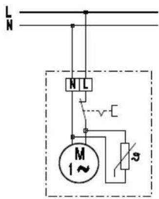
L N N L VZ-F M 1~ECA 120 P
text_image
L N N L M 1~ECA 120 24-V
text_image
L N TRE 50 230/24V ~ N L M 1 ~ECA 120 K

text_image
L N N L M 1~ 2ECA 120 KVZ
text_image
L N S N L 1 2 VZ M 1~ECA 120 KF
text_image
L N N L VZ-F M 20ECA 120 KP