EVN15 - Fan Maico - Free user manual and instructions
Find the device manual for free EVN15 Maico in PDF.

User questions about EVN15 Maico
0 question about this device. Answer the ones you know or ask your own.
Ask a new question about this device
Download the instructions for your Fan in PDF format for free! Find your manual EVN15 - Maico and take your electronic device back in hand. On this page are published all the documents necessary for the use of your device. EVN15 by Maico.
USER MANUAL EVN15 Maico
pl Wentylator okienny
natural_image
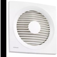
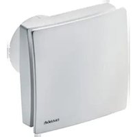
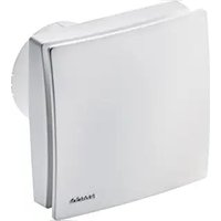
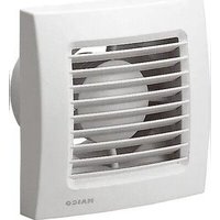
White square HVAC vent with ventilation slots and 'MAICO' logo (no text or symbols on main body)Montage- und
Betriebsanleitung
Mounting and
Operating instructions
text_image
C 7 1 6 5 C1 M5x50mm 4x KLICK! 5 X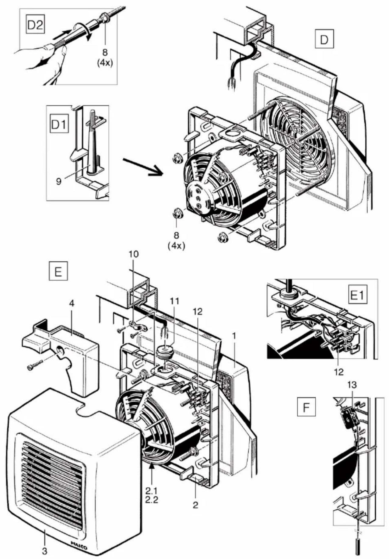
Inhaltsverzeichnis
text_image
QR code image containing encoded data, no visible human-readable text- Scope of delivery......8
- General notes....8
- Product information 8
- Environmental conditions and operating limits....9
- Technical data....9
- Safety instructions....9
- Installation.... 11
- Maintenance.... 12
- Cleaning.... 12
- Fault rectification .... 13
- Spare parts.... 13
- Dismantling .... 13
- Disposal 13
- Wiring diagrams ...... 72
1. Scope of delivery
• Window fan, components assembled
- Socket spanner, width across flats 8, (red)
- Mounting and operating instructions
2. General notes


Read these installation and operating instructions carefully before using the fan for the first time.
Follow the instructions. Keep these instructions safe for use later on.
2.1 Installation staff
Installation is only permitted when carried out by trained specialists.
Only qualified electricians are permitted to make the electrical connections. They are trained in electrical engineering and are aware of the risks and consequences of an electric shock.
2.2 Symbols used

DANGER
Direct risk of danger. Failure to observe will result in severe injury or death.

CAUTION
Possibly dangerous situation which could result in minor to moderate injuries.
NOTICE
Possible situation which could cause damage to the product or its surroundings.

●
INFO symbol indicating important information and tips.
Bullet point for information on the respective subject.
1.
Instructions. Follow the instructions given in the order stated.
3. Product information
• EVN 15 with airstream-operated shutter
- EVN 15 P with airstream-operated shutter and with approx. 1 m long pull-cord for manual operation
- Units with thermal overload protection This switches the motor off under thermal overload and automatically turns it on again after cooling down.
- On/off switching takes place in
- EVN 15 with separate switch provided by the customer
- EVN 15 P with integrated pull-switch. Pull the pull-cord to switch the fan on/off.
Acknowledgements:
© Maico Elektroapparate-Fabrik GmbH. English translation from the original German Operating Instructions. We cannot be held responsible for mistakes or printing errors and retain the right to make technical modifications without giving prior notice.
3.1 Unit Overview, Fig. A to F
1 Shutter, complete
1.1 Lamella
2 Connecting flange with
2.1 Motor and
2.2 Impeller
3 Internal housing
4 Terminal box cover
5 Screw, M5 x 50 mm
6 Adhesive strip
7 Gluing point
8 Lock nut
9 Socket spanner, width across flats 8, red
10 Tension relief
11 Self-sealing grommet
12 Terminal block
13 Pull-switch
S Window cut-out or wall cut-out
3.2 Intended use
- The unit is only intended for domestic use and similar purposes.
- The unit serves for air extraction of restaurants, showrooms, lecture halls, kindergartens, hospitals, foreman's offices and similar rooms.
• Operation is only permitted with: - installation in flat glass windows with single or double glazing.
- installation in thin walls with a pane or wall thickness from 3...30 mm.
- installation in a vertical position.
- an installed shutter and fitted housing.
3.3 Foreseeable cases of misuse
Maico is not liable for damages caused by use contrary to the intended purpose. Under no circumstances should the unit be used:
- in hinged double-glazed windows.
- on ceilings, sloping roofs or sloping walls.
-
close to flammable materials, liquids or gases.
-
to convey chemicals, aggressive gases or vapours.
- in explosive atmosphere.
• for air extraction of kitchen exhaust.
Never dismantle the shutter [1].
4. Environmental conditions and operating limits
- Permissible maximum air temperature 40 °C.
- Sufficient supply air intake must be ensured during operation with air-ventilated fireplaces. The maximum permitted pressure difference per living unit is 4 Pa.
5. Technical data
See rating plate.
6. Safety instructions
6.1 General
- Read through these operating intructions carefully before assembly and commissioning.
- Assembly and electrical connection may only be undertaken by trained specialists in accordance with Chapter 2.1.
- With electrical and unit installation, the relevant regulations must be observed, particularly DIN VDE 0100 with the corresponding parts. In rooms with baths or shower units, e. g., this would be Part 701.
- Only connect unit to permanently wired electrical installations with NYM-O or NYM-J, (0.75 x 1.5 mm²) cables. Use suitable, flexible connecting cable if the unit is installed in a swivel window. Additionally, a mains isolation device with contact openings of at least 3 mm at each pole must be installed.
- The unit may only be operated using the voltage and frequency shown on the rating plate.
- Only operate the unit when it is completely installed.
- Disconnect the unit from the power supply before removing the terminal box cover [4].
- Ensure a sufficient supply air intake.
- Modifications and alterations to the unit are not permitted and release the manufacturer from any guarantee and liability.
6.2 Safe and correct practices during operation
Danger of injury in case of objects in the impeller. Do not insert any objects into the unit.
Danger of injury from rotating impeller. Do not get too close to the fan, to avoid hair, clothing or jewellery being drawn into the unit.
- This fan unit can be used by children aged 8 and above, and by people with reduced physical, sensory or mental capabilities or by persons with insufficient experience or knowledge provided they are supervised by a person responsible for their safety, or they have been instructed about the safe operation of the unit and can understand the resulting risks thereof. Children must not play with the unit. Cleaning and maintenance must not be carried out by children without supervision.
7. Installation, Fig. A ... F
NOTICE
Danger of short-circuits, unit damage Water will penetrate if the power cable is incorrectly fed into the housing or if the self-sealing grommet is not fitted correctly.
The degree of protection is only guaranteed if the cables are fed through correctly at the intended housing seal (self-sealing grommet).
Drill a circular hole into the self-sealing grommet [11] that is somewhat smaller than the cable diameter.

DANGER
Danger of injury due to cuts caused by glass breakage, if the windowpane is under stress.
Only install the windowpane so that the glass is not under stress. If necessary, remove the windowpane and re-fit it so that it is not under stress.
NOTICE
Shutter does not close properly, if it is tensely installed.
Only mount the shutter on a level surface in order to guarantee the shutter function.

Notes
- Make sure there is sufficient space to the window frame, wall or ceiling.
- Never dismantle the shutter.
Fig. A: Installation preparation
- Lay the power cable.
- Get an expert to make the window cut-out [S]. Drill the cut-out [S] in the case of wall / wooden panel installation.
- Clean the windowpane thoroughly before adhesively bonding the shutter on.
Fig. B: Disassembling the inner parts
- To do this, hold the internal housing [3] firmly at the side and pull the connecting flange [2] at the motor out of the cover.
- Remove the terminal box cover [4].
In the case of wall/wooden panel installation
- If necessary drill through the connecting flange [2] on the 2 knockout points [X] ( Fig. B).
- Drill through the 4 knockout points [Y] ( Fig. B1) on the shutter, with the lamellae open.
Fig. C/Fig. C1: Installing the shutter [1] (outside).
- Insert the screws [5] into the eyes of the shutter until they snap into place.
- Remove the protective foil from the gluing points [7].
- Align the shutter in the window cut-out and press it onto the pane.
In the case of wall/wooden panel installation
- Attach the shutter [1] to the wall or wooden panel with suitable mounting material.
Fig. D: Installing the inner parts (inside)

Danger of injury due to cuts caused by glass breakage, if the nuts have been over-tightened.
Tighten the lock nuts [8] carefully making sure not to over-tighten them.
- Attach the connecting flange [2] to the screws [5], align it and press it gently against the windowpane.
- Tighten the lock nuts [8] with the supplied socket spanner [9] ( Figs. D1 and D2).
In the case of wall/wooden panel installation
- Attach the connecting flange [2] to the wall or wooden panel with suitable mounting material.
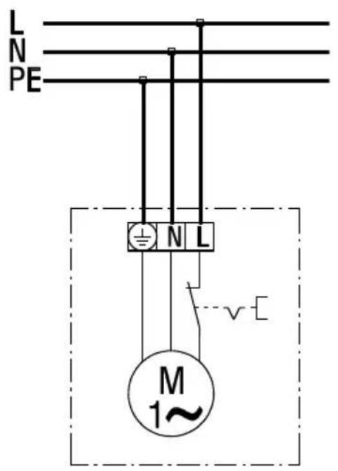
Fig. E: Electrically connect the unit, ☐ wiring diagram in Chapter 14

DANGER
Danger to life from electric shock.
Prior to access to the connection terminals switch off all supply circuits. Switch off mains fuse, secure against being accidentally switched back on and position a visible warning sign.

CAUTION
Danger of short-circuits through incorrect feeding of the power cable into the terminal box.
Feed the power cable correctly through the cable self-sealing grommet and make sure there is cable tension relief.
- Make a circular hole in the self-sealing grommet [11] and insert it into the intended hole.
- Connect the power cable to the terminal block [12] as per the wiring diagram.
- Fit tension relief [10].
- Put the terminal box cover [4] on and screw it into place.
- Hang the internal housing [3] on the top of the connecting flange [2] and clip it into place in the safety catch. Do not twist it.
Fig. F: Only with EVN 15 P Fans:
- Insert the pull-cord into the two housing grooves.
- Position the internal housing [3] as described above.
Start-up
- Switch the mains fuse on.
- Carry out a function test.
8. Maintenance
The unit is maintenance-free.

With units installed in swivel windows
Check the connection cable regularly for signs of damage at the transfer point from the window sash to the window frame.
If damaged, further operation of the unit is not permitted. The unit must be disconnect from the power supply (switch off the mains fuse and secure it against being switched back on again). Have the connection cable replaced by a trained electrician.
9. Cleaning

DANGER
Danger to life from electric shock.
Prior to access to the connection terminals switch off all supply circuits. Switch off mains fuse, secure against being accidentally switched back on and position a visible warning sign.
Damage to the cover caused by cleaning in a dishwasher.
Do not clean the internal housing in a dishwasher.
- Hold the internal housing [3] at the bottom, on the right and left side and, pulling equally on both sides, pull it forwards and off.

Do not pull the internal housing [3] off by the internal grille or the upper edge.
- Clean the internal parts with a dry cloth. If necessary, use a vacuum cleaner. Swivel the lamellae upwards to clean the shutter.

Do not use aggressive, harmful or easily flammable cleaning agents for cleaning work.
- Attach the internal housing [3] (Fig. E).
Call on the services of a trained electrician any time there is a fault. Repairs should only be carried out by a trained electrician.

DANGER
Danger to life from electric shock when working on electrical equipment!
Prior to access to the connection terminals, switch off all supply circuits. Switch off mains fuse, secure against being accidentally switched back on and position a visible warning sign.
A fault can occur if, for example, the air-stream temperature increases or if the fan motor is blocked.

If the fan motor overheats, the thermal overload protection reacts. In the case of thermal overload, it switches the motor off and automatically turns it on again after the motor has cooled down.
- Let the fan motor cool down.
- Check if the mains fuse is switched on and if the fan starts independently after cooling.
- If necessary, clean the unit according to the instructions in Chapter 9.
- Ensure the environmental conditions according to Chapter 4.
- If the fault still continues or occurs again, switch off at the mains fuse and call on the services of a trained electrician.
11. Spare parts

Spare parts may only be sourced from and fitted by a specialist installer.
| Item | Designation | Type | Article no. |
| 1 | Shutter, complete | 15 15 P | 0059.0144.9000 |
| 2 | Connecting flange, complete | 15 | E059.0140.9000 |
| 2 | Connecting flange, complete | 15 P | E059.0140.9100 |
| 2.1 | Motor with screws | 15 | 0156.0093.0001 |
| 2.2 | Impeller with clamping ring | 15 15 P | 0061.0119.0000 |
| 3 | Internal housing, complete | 15 | 0059.0141.9000 |
| 3 | Internal housing, complete | 15 P | E059.0141.9100 |
| 13 | Pull-switch, complete | 15 P | E157.0794.0000 |
In the case of questions:
Dismantling may only be undertaken by a trained electrician ( Chap. 1).

DANGER
Danger to life from electric shock.
Prior to access to the connection terminals switch off all supply circuits. Switch off mains fuse, secure against being accidentally switched back on and position a visible warning sign.
13. Disposal

Do not dispose of in domestic waste.
The unit contains in part materials that can be recycled and in part substances that should not end up in the domestic waste.
Dispose of the unit once it has reached the end of its service life according to the regulations valid where you are.
Sommaire
text_image
L N PE ± N L M 1~