EVH 31 - Fan Maico - Free user manual and instructions
Find the device manual for free EVH 31 Maico in PDF.
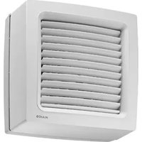
| Product type | Extraction fan with manual pull cord interior shut-off |
| Brand | Maico |
| Model | EVH 31 |
| Interior housing dimensions (W x H x D) | 410 x 410 x 130 mm |
| Exterior grille dimensions (W x H x D) | 410 x 410 x 23 mm |
| Glass cut-out diameter | 360 mm |
| Net weight | 6.4 kg |
| Power supply | See rating plate (voltage and frequency) |
| Control type | Manual pull cord (length 1 m) |
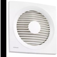
| Function | Air extraction |
| Maximum conveyed fluid temperature | +40 °C |
| Motor thermal protection | Yes (automatic shutdown on overload) |
| Installation | Vertical in window or thin partition |
| Maintenance | Clean with a damp cloth; do not immerse |
| Safety | Do not insert objects; use only with exterior grille |
| Spare parts available | Interior housing, exterior grille, locking mechanism, VM motor transmission |
| Intended use | Air extraction from offices, industrial premises, workshops, etc. |
Frequently Asked Questions - EVH 31 Maico
User questions about EVH 31 Maico
0 question about this device. Answer the ones you know or ask your own.
Ask a new question about this device
Download the instructions for your Fan in PDF format for free! Find your manual EVH 31 - Maico and take your electronic device back in hand. On this page are published all the documents necessary for the use of your device. EVH 31 by Maico.
USER MANUAL EVH 31 Maico
natural_image
Line drawing of a white industrial air conditioner unit with ventilation grilles and a label 'MAISO' (no text or symbols on the device itself)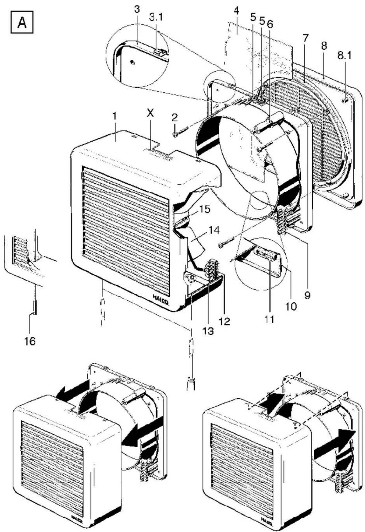
text_image
A 1 X 2 3 3.1 4 5 5.6 7 8 8.1 15 14 13 12 11 9 10 16 HAICOtext_image
Technical diagram of a mechanical assembly with numbered components and cross-sectional viewsnatural_image
Technical diagram of a mechanical component with cross-section view and labeled parts (no readable text or symbols)EV 31, EVR 31 and EVH 31
Scope of delivery
- Internal housing, complete
- Connecting flange
- External grille
- Assembly instruction
- Accessories
Table of contents
Scope of delivery.... 10
- Warning symbols.... 10
- Product information .... 10 Equipment overview .... 10 Product description.... 11
-
Technical Data .... 11 Dimensions and weight .... 11 Rated voltage and frequency.... 11
-
Environmental conditions and operating limits .... 11
-
Essential safety instructions.... 11 General safety instructions.... 11 Intended use.... 11 Predictable misuses.... 11 Safe and correct practices during operation.... 12
-
Installation preparation .... 12 Installation in windows .... 12 Installation in walls and wooden panels 12 Dismantling internal housing with connecting flange .... 12
-
Installation....13 Installation in windows....13 Installation in walls and wooden panels 13 Electrical connection....14 Internal housing installation....14
-
Operation 15
-
Maintenance.... 15 With fans in swivel windows .... 15
-
Cleaning 15
-
Dismantling ventilation unit.... 15
-
Fault rectification.... 16
-
Spare parts.... 16
-
Disposal 16
Wiring diagram 25
1. Warning symbols

Danger to life Non-observance can lead to death or serious bodily injuries.

Danger of injury Non-observance can lead to serious bodily injuries

Danger of injury Non-observance can lead to minor or more serious bodily injuries.
NOTICE
Property damage. Non-observance can lead to damage to property.
2. Product information
Equipment overview, Figure A
1 Internal housing, complete
EV 31, EVR 31: With electrical internal shutter
EVH 31: Internal shutter with pull-cord for manual operation
2 Screw
3 Connecting flange
3.1 Locking hook
4 Window pane
5 Cable grommet
6 Capacitor
7 Window pane ring
8 External grille
8.1 Housing dome
9 Connection terminal socket
10 Window pane ring
11 Ball
12 Connection terminal plug
13 Catch
14 Impeller
15 Motor
16 EVH 31: Pull-cord
X Rating plate
Imprint: © Maico Elektroapparate-Fabrik GmbH. E & OE. We reserve the right to make technical modifications.
Product description Wiring diagram, see page 25
- EV 31 with electrical internal shutter. For air extraction. Speed controllable. On/off with light switch or separate switch (all to be supplied by customer). The fan unit switches on/off immediately when the switch is operated. Internal shutter opens/closes automatically.
- EV 31 with electrical internal shutter. For ventilation or air extraction. Speed controllable. On/off with light switch or separate switch (all to be supplied by customer). The fan unit switches on/off immediately when the switch is operated. The internal shutter opens/closes automatically.
- EVH 31 with internal shutter and 1 metre long pull-cord for manual operation. For air extraction. The fan unit switches on/off by pulling the pull-cord. The internal shutter opens/closes automatically.
3. Technical Data
- See rating plate.
Dimensions and weight
- Internal housing: 410 x 410 x 130 mm
• External grille: 410 x 410 x 23 mm
• Window cut-out: 360 mm diameter
• EV 31, EVR 31: 7.6 kg
• EVH 31: 6.4 kg
Rated voltage and frequency
- See rating plate.
4. Environmental conditions and operating limits
- Maximum permitted temperature of the air medium: +40 °C
- Sufficient supply air intake must be ensured during operation with air-ventilated fireplaces. The maximum permitted pressure difference per living unit is 4 Pa.
5. Essential safety instructions
General safety instructions
- Read the safety instructions through carefully before commissioning.
- Keep the instructions.
- The device must not be used as a toy.
- Installation is only permitted when carried out by trained specialists.
- Electrical connections and repairs only permitted when carried out by electricians.
- Only connect the unit to a permanent electrical installation.
Permitted cable cross section: 0.75 mm ^2 to 1.5 mm ^2 .
Use suitable, flexible connecting cable if the unit is installed in a swivel window. Mains isolation device required with contact openings of at least 3 mm at each pole.
- The fan unit may only be operated using the voltage and frequency shown on the rating plate.
- Do not make any modifications to the fan unit.
- Only operate the fan unit when it is completely installed. Never operate without an external grille.
- Operation is only permitted when the internal housing is in place and locked shut.
Intended use
- EV 31 and EVH 31: For air extraction at offices, business and commercial premises, restaurants, manufacturing and workplaces, doctors practices, etc.
- EVR 31: For ventilation or air extraction of the above-mentions premises.
- For vertical installation in windows or thin walls.
- In hinged double-glazed windows, composite windows and glass brick walls, only with the suitable Maico accessory ZD or ZG.
Predictable misuses
Maico is not liable for damages caused by use contrary to the intended purpose. Under no circumstances should the unit be used:
- on sloping walls, pitched roofs or ceilings.
- close to flammable materials, liquids or gasses.
• in explosive atmospheres.
Safe and correct practices during operation
- Danger of injury Do not insert any objects in the unit.
- Danger from self-turning impeller Do not get too close to the unit to avoid hair, clothing or jewellery being drawn into the unit.
- The unit is not intended to be used by people whose physical, sensory or mental capabilities are not sufficient for them to understand and put into practice the safety information provided in these instructions. This restriction also applies to children. The unit may however be safely used by such persons if they are supervised by someone responsible for their safety or if they are instructed in a suitable way.
6. Installation preparation
Installation in windows

Danger of cuts caused by sharp glass edges and glass breakage. Damage to the window pane from material stress.
If necessary, extract the window pane and putty it back in place without stress.
NOTICE
Functional impairment and unit damage if installed on an uneven substrate.
Make sure there is a level seating in the area of the window pane rings [7] and [10].

Danger of short-circuits with sloping installation position through the build-up of condensation inside the housing.
Only install the unit vertically, with the cable feed from above.
➢ Decide on the installation position. Maintain sufficient distance (min. 50 mm) from the window frame or wall/ceiling. Allow enough space for a correct cable feed and the opening area of the window.
➢ Get an expert to make the window cut-out – diameter 360 mm.
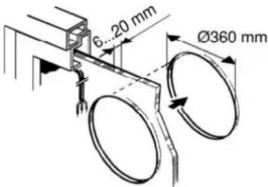
text_image
6...20 mm Ø360 mm▶ Lay the power cable.
Installation in walls and wooden panels
Make the same preparations for the installation in walls and wooden panels as described under Installation in windows.
Dismantling internal housing with connecting flange, see Figure A, bottom left.
➢ Loosen both catches [13] with a screwdriver.
➢ Hold on to the internal housing, slightly angle the connecting flange and disconnect it from both locking hooks [3.1].
➢ Pull the connection terminal plug [12] off.
Remove the testing cables from the connection terminal socket [9]. These are no longer required.
7. Installation
Installation in windows
NOTICE
Faulty operation and unit damage caused by a rubbing impeller [14] with incorrect installation.
Do not install the internal housing twisted or crimped.

The internal housing [1] should only be installed indoors. Outdoor installation of the internal housing [1] is not permitted.
➢ Press the external grille [8] and the connecting flange against the window pane from outside and inside respectively.
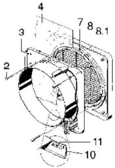
text_image
Technical diagram of a mechanical device with numbered components and cross-sectional views➢ Line the external grille and connecting flange up horizontally and bolt them together with the M5 x 25 bolts supplied [2]. The ball [11] can be used to help if unlatched first.

Danger of injury through glass breakage if the bolts are over-tightened.
- Tighten the bolts carefully and do not over-tighten them.
Make sure you have enough sealant, e.g. silicone in the case of special, e.g. corrugated glass.

Notes
- Make sure there are no leaks at the window pane rings [7] and [10].
- In the case of a window pane that is > 8 mm thick, replace the supplied bolts [2] with other suitable ones, of your own choosing.
Installation in walls and wooden panels
➢ Drill through the 4 housing domes [8.1] on the external grille – diameter 5.5 mm.
➢ Install the external grille and connecting flange as described before.
➢ Mark additional drill holes on the wall through the housing domes [8.1].
➢ Loosen the mountings a little and turn the external grille with the connecting flange in the wall breakthrough by approx. 45°.
▶ Drill through the wall (4 holes).
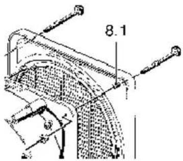
text_image
8.1➢ Line up the external grille with the connecting flange again and bolt them together as described before.
Additionally, the external grille is fixed to the connecting flange through the 4 drilled holes. Make sure that suitable bolts and nuts are available on site.
Electrical connection

Danger to life from electric shock
Switch the mains fuse off.

Unit damage in the case of short-circuits
➢ Cut off and insulate any unnecessary cable cores.

Danger of short-circuits through incorrect feeding of the power cable into the housing.
➢ Feed the power cable professionally through the cable grommet and make sure there is tension relief. See printed cable run.
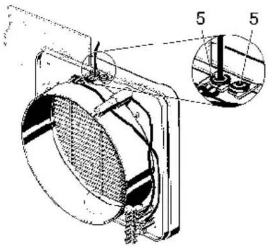
natural_image
Technical line drawing of a mechanical component with cross-sectional view and numbered annotations (no readable text or symbols)➢ Locate both cable grommets [5] in the connecting flange.
➢ Feed the power cable through the open cable grommet.
Connect the power cable to the connection terminal socket [9] as shown in the wiring diagram on Page 25.
Internal housing installation
see also Figure A, bottom right

Danger of short-circuits and unit damage with wrong polarity
Make sure the polarity is correct, see labels A and B.
NOTICE
Damage to the contact holder caused by tearing or pulling on the plug cable
➢ Always hold the internal housing near the connecting flange to avoid pulling tension at plug connection.
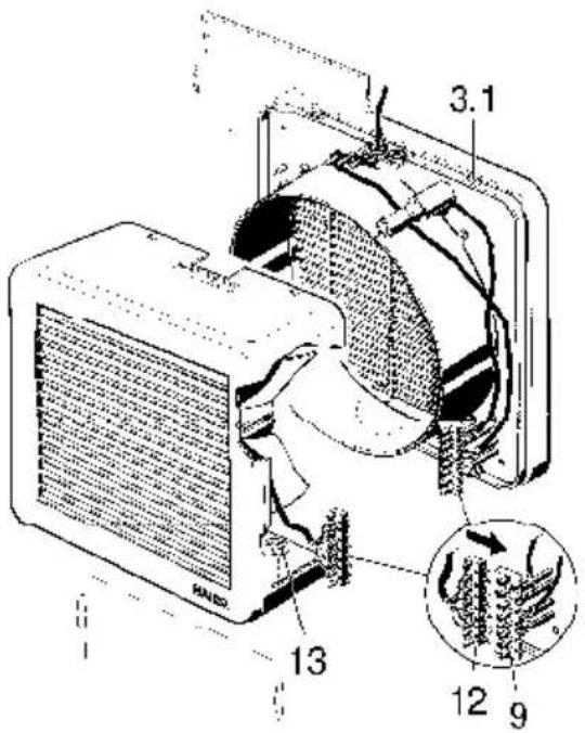
text_image
3.1 13 12 9➢ Plug the connection terminal plug [12] on to the connection terminal socket [9].
➢ Push the internal housing parallel onto the connecting flange as shown bottom right in Figure A.

The internal housing must clip into the upper locking hooks [3.1]. Don't trap the cables.
➢ Close both catches [13] with a screwdriver.
Switch the mains fuse on.
➢ Carry out a function test.
8. Operation
EV 31
Switch the unit on using the switch, e.g. speed controller ST...
The internal shutter opens automatically. The fan unit runs and extracts air from the room.
➢ Switch the unit off with the switch.
The internal shutter closes.
The fan unit switches off.
EVR 31
Switch the unit on using the switch, e.g. reversing switch STW... The internal shutter opens automatically. The fan unit runs and ventilates or extracts air from the room.
➢ Switch the unit off with the switch. The internal shutter closes. The fan unit switches off.
EVH 31
NOTICE
Unit damage by jerky pulling at the pull-cord
Don't pull the pull-cord in a jerky way.
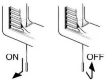
text_image
ON OFFSwitch the unit on by pulling the pull-cord angled towards the front.
The internal shutter opens mechanically. The fan unit runs and extracts air from the room.
➢ Switch the unit off by pulling the pull-cord angled towards the window or wall and then return it to its base position.
The internal shutter closes mechanically. The fan unit switches off.
9. Maintenance
The unit is maintenance-free.
With fans in swivel windows
➢ Check the connection cable regularly for signs of damage at the transfer point from the window sash to the window frame.
If the cable is damaged, have it replaced by a trained electrician.
10. Cleaning

Danger to life. Unit is powered up
Switch the mains fuse off.
Do not remove the internal housing for cleaning.
➢ Do not flood the unit with liquid.
▶ Clean the unit with a damp cloth.
11. Dismantling ventilation unit see also Figure A, bottom left

Danger to life from electric shock
▶ Switch the mains fuse off.
▶ Open both catches [13].
➢ Swing the internal housing up slightly and remove it.
➢ Disconnect the electrics.
➢ Remove the connecting flange and external grille.
- Call on the services of a trained electrician any time there is a fault.
- Repairs should only be carried out by a trained electrician.

Danger to life. Unit is powered up
▶ Switch the mains fuse off.
| Fault Countermeasure | |
| Unit doesn’t run. Thermal overload protection of the motor switches unit off and back on again after cooling down. | Localise the cause of the fault and rectify it. |
Tab. 1: Fault rectification
14. Disposal
Not in domestic waste. The unit contains in part material that can be recycled and in part substances that should not end up as domestic waste.
➢ Dispose of the unit once it has reached the end of its working life according to the regulations valid where you are.
13. Spare parts

When ordering spare parts, always quote the print number 0185.0853.0007 from these instructions, the rating plate number "X" and the corresponding item number.
| Item, Page 2Figure A | Designation |
| 1 Internal | housing, complete– EV 31, EVR 31– EVH 31 |
| 8 External | grille VM |
| 13 | Catch |
| 15 | VM motor– EV 31, EVR 31 |
Tab. 2: Spare parts