EN 20 - Fan Maico - Free user manual and instructions
Find the device manual for free EN 20 Maico in PDF.
| Product type | Wall fan for air extraction (EN model) or reversible extraction/insufflation (ENR model) |
| Brand | Maico |
| Model | EN 20 |
| Category | Fan |
| Power supply | 230 V, 50 Hz, cable cross-section 1.5 to 2.5 mm² |
| Motor protection | Thermal overload protection (automatic reset) |
| Maximum fluid temperature | +40 °C |
| Minimum wall thickness | 105 mm (EN 20) |
| Installation type | Flush or surface mounted (wall, ceiling, attic) |
| Main functions | Air extraction; reversible option (ENR) for insufflation |
| Included accessories | Interior cover, terminal box cover, assembly sleeve, impeller, motor |
| External shutter required | MK, BK or AS models (not supplied) |
| Electrical connection | 3-pole terminal block (EN) or 4-pole (ENR); wiring diagrams in the instructions |
| Protection rating | Guaranteed by correct drilling of cable glands and sealing gasket |
| Cleaning | Dust off with a dry cloth or vacuum cleaner; do not immerse |
| Maintenance | No maintenance required; periodic cleaning recommended |
| Safety | Do not use without interior cover or external shutter; disconnect all poles before intervention |
| Spare parts | Interior cover, terminal box cover, sleeve, capacitor (ENR), regulator, motor, impeller, external shutter |
| Repairability | Repairs by qualified electrician; parts available under reference |
| Warranty | Manufacturer warranty per conditions; modifications void warranty |
| General information | Manual available in French; VDE 0100 compliant |
Frequently Asked Questions - EN 20 Maico
User questions about EN 20 Maico
0 question about this device. Answer the ones you know or ask your own.
Ask a new question about this device
Download the instructions for your Fan in PDF format for free! Find your manual EN 20 - Maico and take your electronic device back in hand. On this page are published all the documents necessary for the use of your device. EN 20 by Maico.
USER MANUAL EN 20 Maico
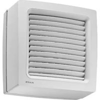
natural_image
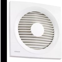
Close-up of a white square fan with a circular vent, showing internal horizontal slats and a central hole (no text or symbols)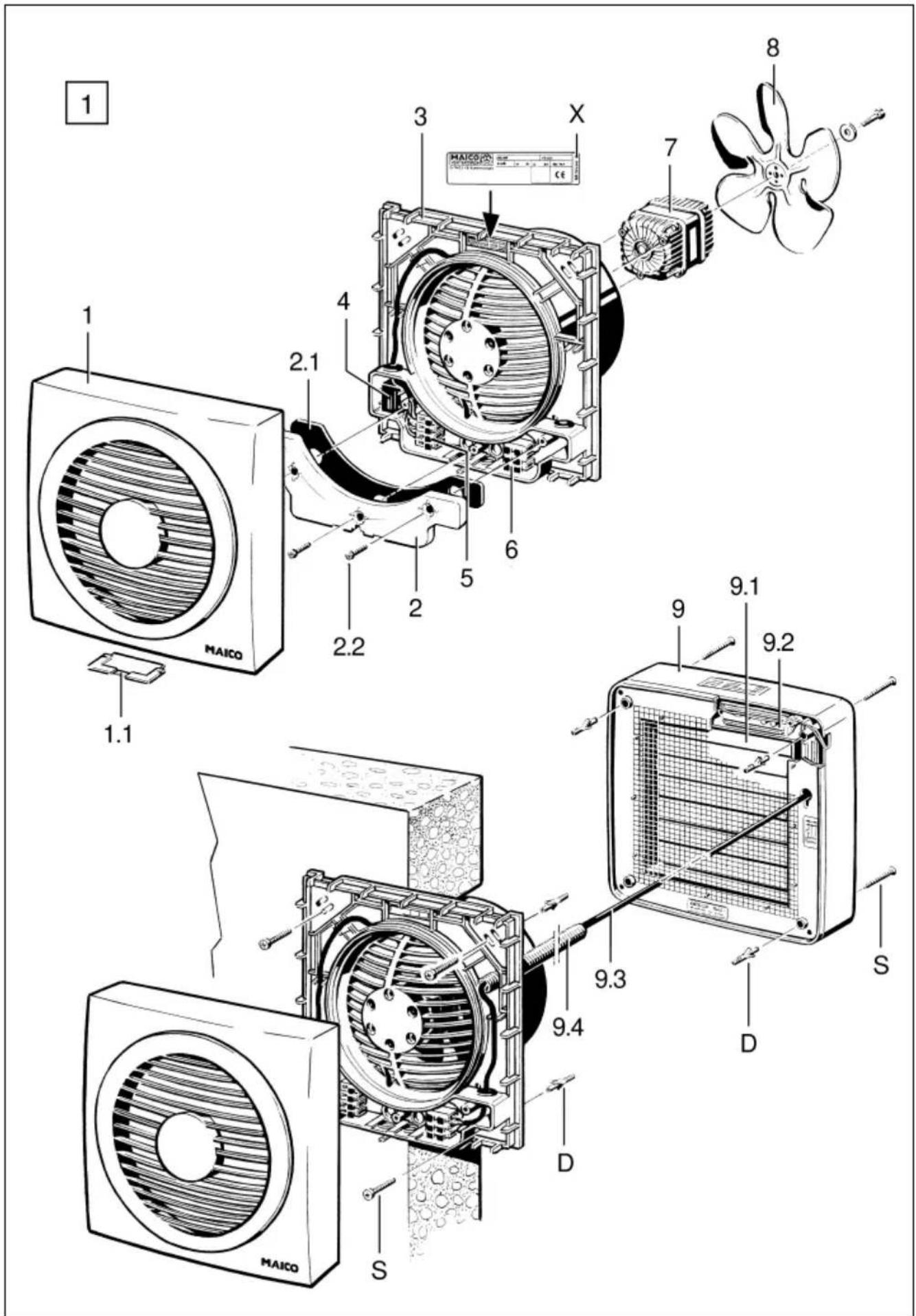
text_image
Technical diagram of a multi-stage air conditioning system with labeled components and parts, including fan, fan blade, fan blade, and fan blade assembly.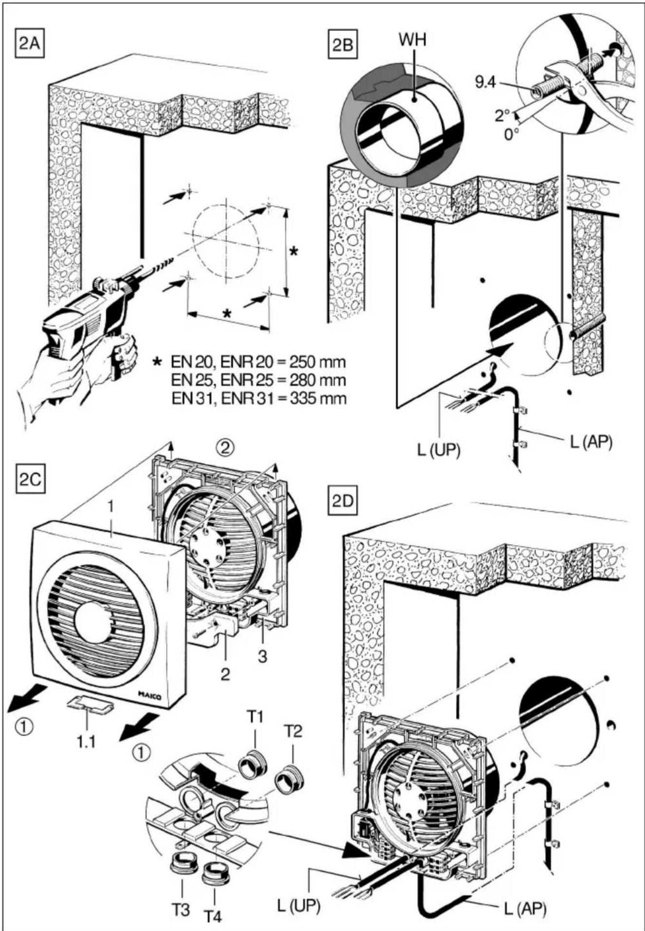
text_image
2E 3 2G 5 6 D 2F 9 1 3 9.3 S 9.4 T5 2G 1 Nm (3x) 2 2.1 2H MAICO1. Warning symbols in this manual

Danger to life!
Non-observance can lead to death or serious bodily injuries.
DANGER

Danger of injury/Property damage!
Non-observance can lead to minor or more serious bodily injuries or property damage.
2. Product information
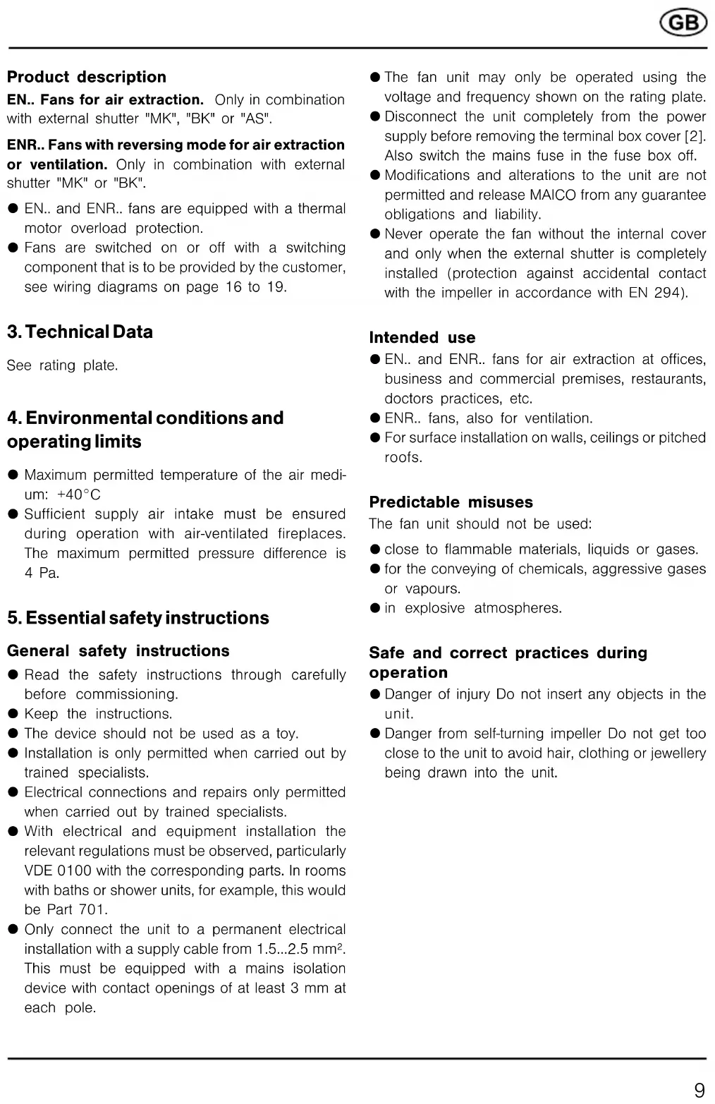
Equipment overview, Figure 1

Spare parts are printed bold. With spare part orders, please quote the manual print number (see rear of envelope), the unit type and the corresponding item number.
1 Internal cover, complete
1.1 Protective bar
2 Terminal box complete
2.1 Sealing
2.2 Screws (3 pieces)
3 Connecting flange complete
4 Capacitor (ENR..)
5 Terminal block (EN.. 3-pin, ENR.. 4-pin)
6 Terminal block (3-pin)
7 Motor, complete
8 Impeller, complete
9 External shutters (= accessory) Shutter "MK" (see figure) Shutter "BK" or airstream-operated external shutter "AS" (no picture)
9.1 Lamella
9.2 Gear motor
9.3 Connecting cable
9.4 Cable conduit
D Dowel (to be supplied by the customer)
S Fixing screw (to be supplied by the customer)
X Rating plate
Acknowledgements
© Maico Elektroapparate-Fabrik GmbH. This instruction is a translation of the German original operating instructions. We are not responsible for mistakes or printing errors and retain the right to make technical modifications without giving prior notice.
Product description
EN.. Fans for air extraction. Only in combination with external shutter "MK", "BK" or "AS".
ENR.. Fans with reversing mode for air extraction or ventilation. Only in combination with external shutter "MK" or "BK".
● EN.. and ENR.. fans are equipped with a thermal motor overload protection.
● Fans are switched on or off with a switching component that is to be provided by the customer, see wiring diagrams on page 16 to 19.
3. Technical Data
See rating plate.
4. Environmental conditions and operating limits
● Maximum permitted temperature of the air medium: +40°C
- Sufficient supply air intake must be ensured during operation with air-ventilated fireplaces. The maximum permitted pressure difference is 4 Pa.
5. Essential safety instructions
General safety instructions
- Read the safety instructions through carefully before commissioning.
- Keep the instructions.
● The device should not be used as a toy.
● Installation is only permitted when carried out by trained specialists.
● Electrical connections and repairs only permitted when carried out by trained specialists. - With electrical and equipment installation the relevant regulations must be observed, particularly VDE 0100 with the corresponding parts. In rooms with baths or shower units, for example, this would be Part 701.
- Only connect the unit to a permanent electrical installation with a supply cable from 1.5...2.5 mm ^2 . This must be equipped with a mains isolation device with contact openings of at least 3 mm at each pole.
● The fan unit may only be operated using the voltage and frequency shown on the rating plate.
- Disconnect the unit completely from the power supply before removing the terminal box cover [2]. Also switch the mains fuse in the fuse box off.
● Modifications and alterations to the unit are not permitted and release MAICO from any guarantee obligations and liability.
● Never operate the fan without the internal cover and only when the external shutter is completely installed (protection against accidental contact with the impeller in accordance with EN 294).
Intended use
● EN.. and ENR.. fans for air extraction at offices, business and commercial premises, restaurants, doctors practices, etc.
● ENR.. fans, also for ventilation.
● For surface installation on walls, ceilings or pitched roofs.
Predictable misuses
The fan unit should not be used:
- close to flammable materials, liquids or gases.
● for the conveying of chemicals, aggressive gases or vapours.
● in explosive atmospheres.
Safe and correct practices during operation
● Danger of injury Do not insert any objects in the unit.
● Danger from self-turning impeller Do not get too close to the unit to avoid hair, clothing or jewellery being drawn into the unit.
6. Installation
Faulty operation and unit damage caused by a rubbing impeller with incorrect installation.
Install the connecting flange so that it is not under tension.
Make sure there is a level seating.

Important notes
● Wall thickness EN/ENR 20, EN/ENR 25 = min. 105 mm
Wall thickness EN/ENR 31 = min. 130 mm
● Make sure there is sufficient space to the wall or ceiling.
- In order to guarantee the degree of protection (IP value), the cable grommets [T...] must be drilled through/pierced correctly, i.e. with a circular hole that is somewhat smaller than the cable diameter.
● Never dismantle the external shutter.
- Only mount the external shutter on a level surface in order to guarantee the shutter function.
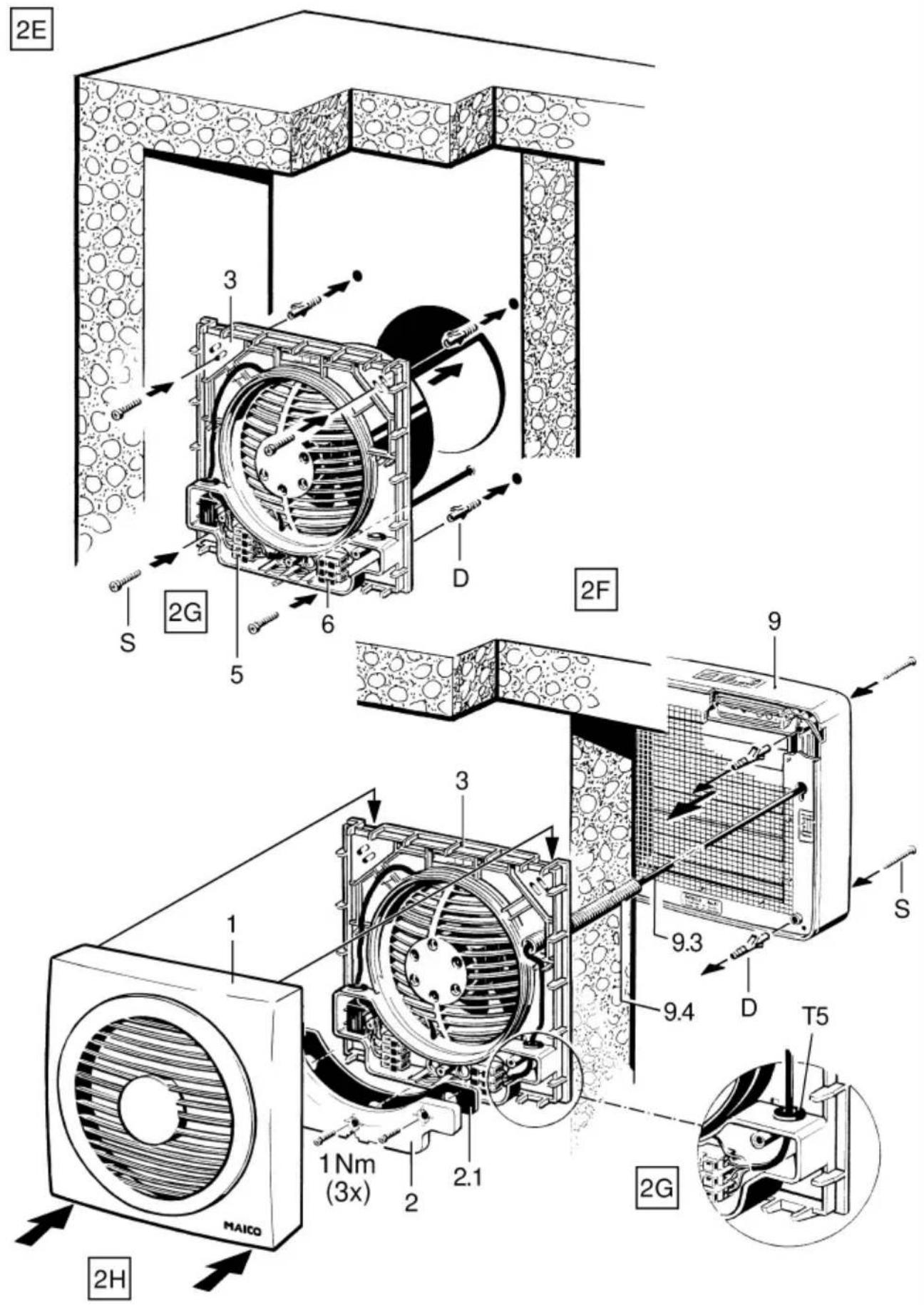
Wall mounting (Figures 2A and 2H)
A Mark and drill the holes for the plugs. Please refer to Figure 2A for the correct hole spacing for the connecting flange.
B Wall breakthrough, install power cable [L] (surface mounted „AP“ or recessed mounted „UP“) and wall sleeve „WH“, as required). Lay an empty ducting [9.4] with a slight incline towards the outside, for an electrically operated external shutter.
C Remove the internal cover [1]; the cover can be removed from the connecting flange [3] without using any tools. To do this, hold onto the connecting flange, open the internal cover [1] from the bottom (see ①) and move it upwards (see ②). Then remove the terminal box cover [2]. Remove the protective bar [1.1] first in the case of surface connection.
D Make a circular hole in the corresponding grommet [T...] in the connecting flange and feed the power cable through it.
E Fix the connecting flange [3] to the wall with suitable fixing material.
F Install the external shutter in line with the corresponding instructions. Feed the connection cable through the conduit [9.4] in the connecting flange and then through the black grommet [T5]
into the terminal box, in the case of an electrically operated external shutter. In order to stop moisture getting into the terminal box, make sure that the hole in the grommet is circular and slightly smaller than the diameter of the connection cable.
G Connect up the unit electrics, see wiring diagrams on Pages 16 to 19.

Danger to life from electric shock!
Switch the mains fuse off.
DANGER

Unit damage in the case of short-circuits!
CAUTION
Cut off and insulate PE conductor and individual cable cores that are not required.
Connect the fan to terminal block [5] and the external shutter to terminal block [6] by reference to the corresponding circuit diagram. The connections to terminal block [6] are not necessary in the case of „AS“ airstream operated external shutters.

The degree of protection (IP value) is only guaranteed if the cables are fed through correctly using the intended cable grommets [T1]...[T5].
H Put the terminal box cover [2] on and screw it into position, ensuring that the sealing [2.1] is correctly located.

Important: Tighten the 3 fixing screws of the terminal box cover with a torque of 1 Nm.
Locate the internal housing [1] into position. To do this, hang the internal housing on the top of the connecting flange [3] and then click it down into position. Don't bend or distort it.
- Switch the mains fuse on. Carry out a function test.
Ceiling installation (no picture)
- Carry out the ceiling installation as described in the wall mounting section.

Danger of short-circuits and unit damage by a build-up of condensation in the fan housing.
CAUTION
Thermally insulate the ventilation ducts correctly.
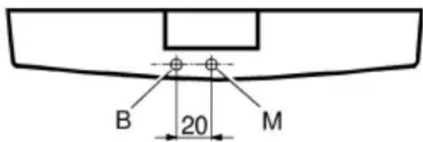
- Drill through the internal cover [1] at position [B] carefully and with a suitable drill bit. The hole prevents the build up of damp and bacteria in the fan housing.
text_image
B 20 M
Observe the dimensioned drawing. Drill hole [B] with a diameter of 3.5 mm, 20 mm to the left of the housing marking [M].
- Secure the internal cover [1] with the supplied screw at marking [M]. 3 × 10 ~mm screw is secured in the internal cover with sticky tape.
7. Maintenance
The unit is maintenance-free.
8. Cleaning

Danger to life! Unit is powered up.
Switch the mains fuse off. Do not flood the unit with liquid.
- Remove the internal cover [1] as shown in Figure 2C. The cover can be removed from the connecting flange without using any tools.
Under no circumstances should the internal cover be pulled from the top or by using the internal grille.
- Clean the internal part with a dry cloth or use a vacuum cleaner if required. Open the flaps upwards to clean the external shutter.

Never use any cleaning agents that may be injurious to health or that are abrasive or easily inflammable.
- Finally, position the internal cover [1] as shown in figure 2H.
Do not clean the internal cover in a dishwasher.
Danger to life! Unit is powered up.
Switch the mains fuse off.
A malfunction can occur, for example, if the airstream temperatures are too high or if the fan motor is blocked. The overload protection device reacts and switches the fan off.
- If the fan fails to operate, always check whether mains power is switched on. If necessary, have the fan's wiring checked by an electrician. Before starting such work, make sure the fan is completely disconnected from the mains.
- Allow the fan motor to cool down and then the fan will switch back on automatically (the thermal switch resets automatically).
- If the unit fails to restart or if it breaks down again, remove the power and call on the services of a specialist.
10. Disposal

Not in domestic waste.
The unit contains in part material that can be recycled and in part substances that should not end up as domestic waste.
- Dispose of the unit once it has reached the end of its working life according to the regulations valid where you are.
Ventilateurs muraux EN 20/ENR 20, EN 25/ENR 25 and EN 31/ENR 31
- Conserver la notice.
- switch
- TH.. thermostat
- HY5 hygrostat
- EAQ air quality controller
* Cable only for MK.. shutter
TRE 5-step transformer (On/Off, 5 speeds)
* Cable only for MK.. shutter
- with On/Off switch and reversing switch
extraction/ventilation
- Terminal 5: air extraction
- Terminal 6: ventilation
* Cable only for MK.. shutter
S1 Marche/Arrêt
FS6 Step switch (air extraction/ventilation, 2 speeds)
FS7 Reversing switch (air extraction - ventila
* Cable only for MK.. shutter
W/WU1 Reversing switch with On/Off
* Cable only for MK.. shutter
TRE 5-step transformer (On/Off, 5 speeds)
W/WU1 Reversing switch (air extraction - 0 - ventilation)
* Cable only for MK.. shutter
- with TRE... 5-step transformer and reversing switch
TRE 5-step transformer (On/Off, 5 speeds)
S1 Reversing switch (air extraction – ventilation)
* Cable only for MK.. shutter
- with TRE..S 5-step transformer and ESS 20 5-step switch
TRE...S 5-step transformer (switch cabinet installation)
ESS 20 5-step switch (On/Off, 5 speeds)
S1 Reversing switch (air extraction/ventilation)
* Cable only for MK.. shutter