AS-6030.3 V2 - Temperature Controller Protector - Free user manual and instructions
Find the device manual for free AS-6030.3 V2 Protector in PDF.
User questions about AS-6030.3 V2 Protector
0 question about this device. Answer the ones you know or ask your own.
Ask a new question about this device
Download the instructions for your Temperature Controller in PDF format for free! Find your manual AS-6030.3 V2 - Protector and take your electronic device back in hand. On this page are published all the documents necessary for the use of your device. AS-6030.3 V2 by Protector.
USER MANUAL AS-6030.3 V2 Protector
natural_image
Diagram of a device showing two batteries with one connected to a power supply (no text or symbols present)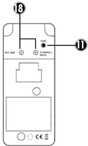
text_image
18 CODE 801/RED SCHINAR2/ BLACK 11WICHTIG
Connection example 1
text_image
N L N 230 V/50Hz L Zuleitung Lüfter MConnection example 2

flowchart
graph TD
    A["STEUERMODUL ABLUFTGERÄT"] --> B["GND / Neutral"]
    A --> C["Stufe 1"]
    A --> D["Stufe 2"]
    A --> E["Stufe 3"]
    A --> F["Stufe 4"]
    G["N 230 V/50Hz"] --> H["L"]
    I["M"] --> J["Ground"]
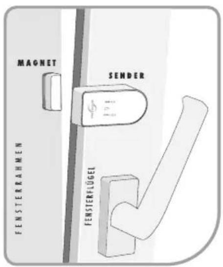
WINDOW TRANSMITTER
text_image
Diagram of a mechanical or optical setup with labeled components and a magnified view showing a component.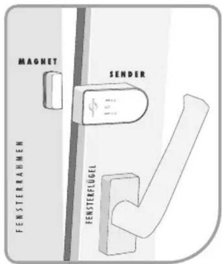
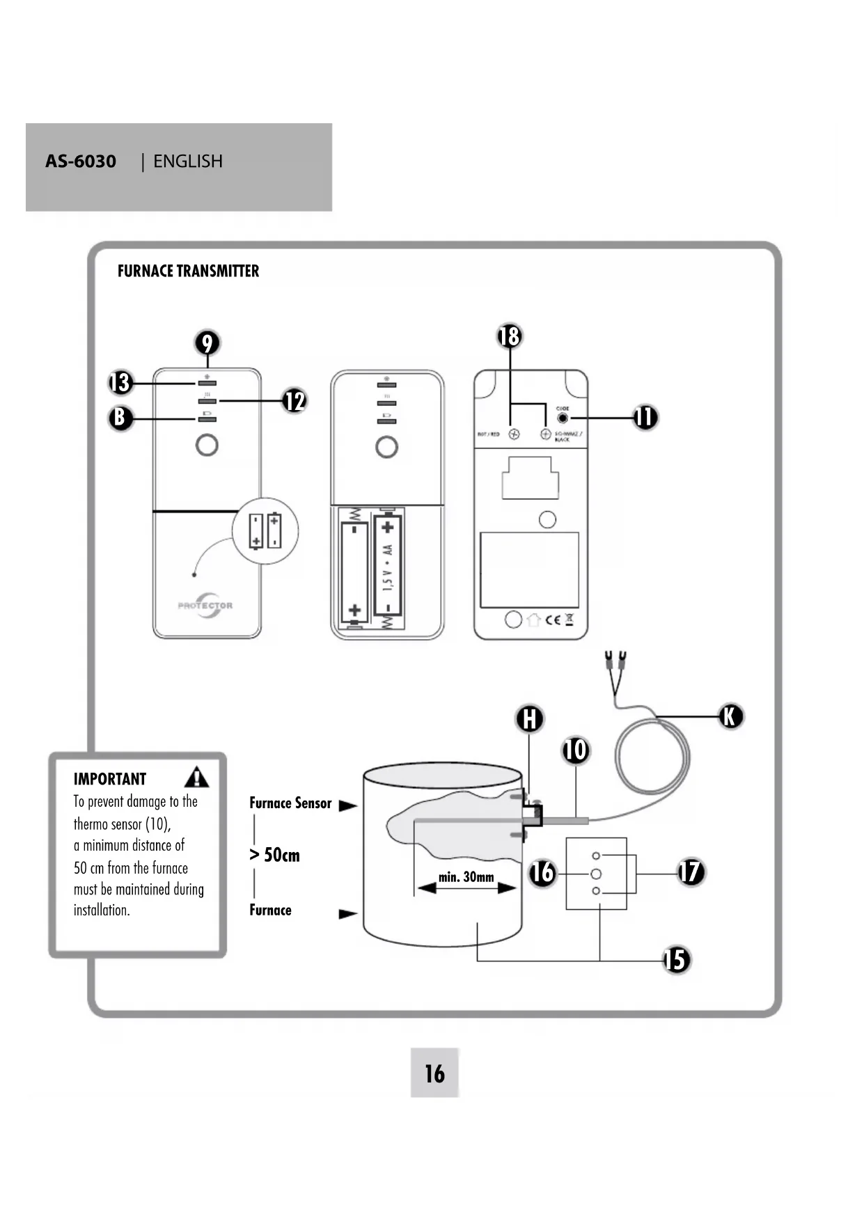
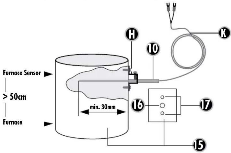
To prevent damage to the thermo sensor (10), a minimum distance of 50 cm from the furnace must be maintained during installation.

text_image
Furnace Sensor > 50cm Furnace min. 30mm H 10 K 16 17 15Assembly and operating instructions for an exhaust air controller Model AS-6030.3
(radio version)
Thank you for purchasing the PROTECTOR AS-6030.3 Exhaust Air Controller.

INTRODUCTION
This device can be used as an exhaust air control device, as an aid to monitor fresh air supply when commissioning an exhaust air device (fume extractor hood, fan etc...). This cannot replace self-monitoring to ensure fresh air supply, but it can be supportive. When the furnace is active (hot stovepipe) this device only activates the exhaust air system in the event of pressure equalisation when a window or door is opened. The additional fresh air streaming in can thus be drawn in from the outside.
GENERAL
This device can be used as an exhaust air control device, as an aid to monitor fresh air supply when commissioning an exhaust air device (fume extractor hood, fan etc...). This cannot replace self-monitoring to ensure fresh air supply, but it can be supportive. When the furnace is active (hot stovepipe) this device only activates the exhaust air system in the event of pressure equalisation when a window or door is opened. The additional fresh air streaming in can thus be drawn in from the outside.

ATTENTION: When using this device for exhaust air control, the shutter must be open to ensure adequate inflow of fresh air!
KEY
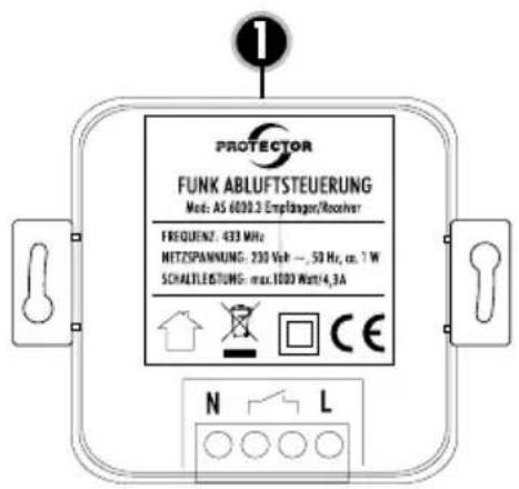
1 AS-6030.3 Receiver
2 Code button Test/Coding
3 LED Status
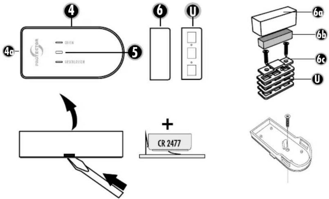
4 Window transmitter
5 LED Status
6 Magnet for window transmitter
U Washers
9 Furnace transmitter
10 Thermo-sensor
11 Status button Furnace transmitter
12 LED Furnace hot (red)
13 LED Furnace cold (green)
14 Battery compartment lid
B Battery control LED
K Sensor cable
- Exhaust pipe
- Feedthrough hole (4 mm)
- Fastening holes (2 mm)
H Holder
USE OF ADDITIONAL TRANSMITTERS
The device can be expanded with one window and one furnace transmitter, whereby the extractor hood is no longer bound to an individual window or furnace. Each individual window transmitter can enable the exhaust unit and each individual furnace transmitter can disable the exhaust unit.
ASSEMBLY OF THE RECEIVER
The assembly must be performed by a qualified electrician! Attention! Only use device inside a building!
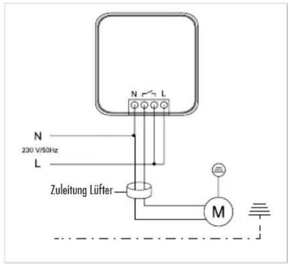
Connection example 1
The receiver can be installed surface mounted or flush in a distributor, switch or plug socket with min. 60 mm diameter.
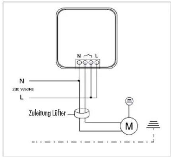
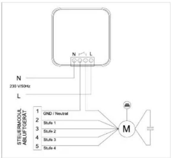
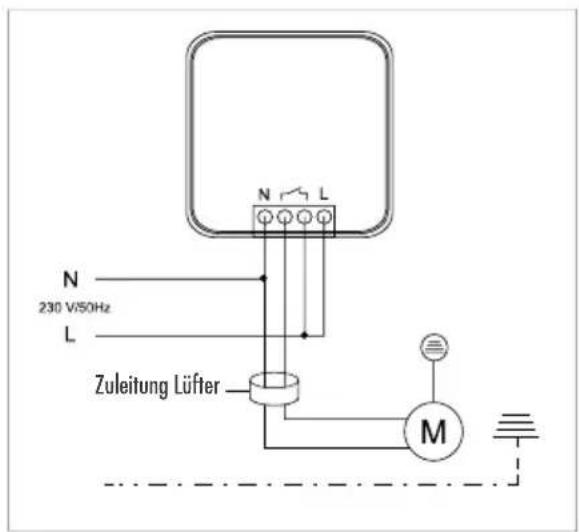
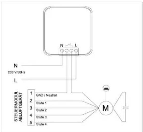
Connection example 2
In the case of exhaust air devices with blower stage switching, the receiver is interposed in the fan motor supply line so that the lighting functions independently of the receiver (see drawing).

ATTENTION: Always check whether the power consumption of the connected device is less than or equal to the switching capacity.
Calculation table to determine the minimum opening of your window (Table 1)
| Window area in m^2 | |||||||||||||||
| m^2 | 0,2 | 0,3 | 0,4 | 0,5 | 0,6 | 0,7 | 0,8 | 0,9 | 1 | 1,1 | 1,2 | 1,3 | 1,4 | 1,5 | |
| cm^2 | 2000 | 3000 | 4000 | 5000 | 6000 | 7000 | 8000 | 9000 | 10000 | 11000 | 12000 | 13000 | 14000 | 15000 | |
| Maximum permitted exhaust air performance in m^3/h | |||||||||||||||
| Extent of window opening | 5 cm | 199 | 252 | 297 | 337 | 373 | 406 | 437 | 466 | 493 | 519 | 544 | 568 | 591 | 613 |
| 6 cm | 246 | 311 | 365 | 413 | 456 | 495 | 532 | 567 | 600 | 631 | 661 | 690 | 717 | 744 | |
| 7 cm | 294 | 369 | 432 | 488 | 538 | 585 | 628 | 668 | 707 | 743 | 778 | 811 | 843 | 874 | |
| 8 cm | 342 | 427 | 500 | 563 | 621 | 674 | 723 | 770 | 813 | 855 | 895 | 933 | 970 | 1005 | |
| 9 cm | 389 | 486 | 567 | 639 | 704 | 763 | 819 | 871 | 920 | 967 | 1012 | 1055 | 1096 | 1136 | |
| 10 cm | 437 | 544 | 635 | 714 | 786 | 852 | 914 | 972 | 1027 | 1079 | 1128 | 1176 | 1222 | 1266 | |
| 11 cm | 485 | 603 | 702 | 790 | 869 | 942 | 1009 | 1073 | 1133 | 1191 | 1245 | 1298 | 1348 | 1397 | |
| 12 cm | 532 | 661 | 770 | 865 | 951 | 1031 | 1105 | 1174 | 1240 | 1302 | 1362 | 1419 | 1475 | 1528 | |
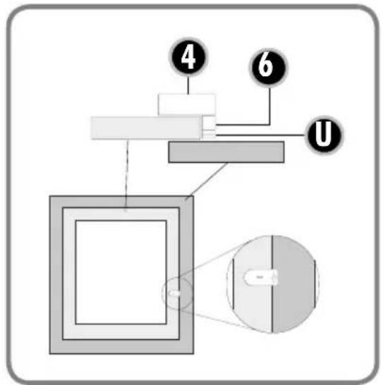
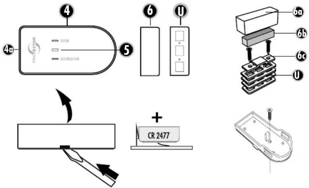
ASSEMBLY OF THE WINDOW TRANSMITTER
Preparation
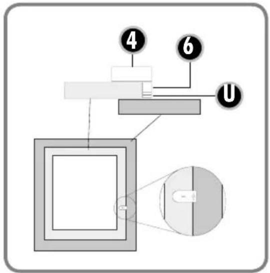
Mount the window transmitter (4) and magnet (6) on the upper window frame and the window casement so that the distance on all sides of the two housing parts with closed window is less than 7 mm. To adjust, use the enclosed washer parts for this (U).
-
Determine the intended location for the window transmitter and magnet and clean adhesive areas. Mount the housing lower section of the window transmitter (4) at the intended location with the enclosed double-sided adhesive pad. Alternatively, a prepared hole is located in the housing lower section, through which the window transmitter can be screwed to the window frame. For this, remove the board from the housing lower section and screw the housing tight with the enclosed washer. Replace the board after this.
-
Insert the battery with correct polarity into the window transmitter (4) lower section. Note: Make sure that the battery of the transmitter is placed on the metal tie bar and do not slide it below this.
- Press the housing upper section of the window transmitter onto the housing lower section.
- Mount the housing lower section with the magnet (6) at the intended location with the enclosed adhesive pad.

ATTENTION: The distance between the transmitter and magnet with closed window must not exceed 7 mm and please ensure a firm and correct fit of the individual components.
- Insert magnet and close with the magnet housing upper section (6).
MINIMUM WINDOW OPENING
Before installation you should determine the minimum opening of the monitored window which is based on:
a) The power of the exhaust air device in m^3/h
b) The size of the window to be opened in m^2
c) The size of the window opening in cm (see table 1)
Most kitchens have rectangular tilt and pivot windows.
If your window is round for example, please ask the installation and heating engineers or electrician to calculate the minimum opening.
The minimum opening of rectangular windows is shown as an example in the table for the tilt and pivot position.
Calculation table to determine the minimum opening of your window
- Determine the extraction power of your exhaust air extraction device unit in m^3/h . You can find the exhaust air extraction power on the identification plate or in the operating instructions of your exhaust air device (e.g. extractor hood).
- Measure the inner width and height of the window and calculate the window size in m^2 .
$$ \begin{array}{l} \text {(width x height = m^ {2} ; e.g. 0.8 m x 1.0 m = 0.8 m^ {2}) =} \ \text {window size} \end{array} $$
- Using the table, work out the opening size (minimum opening for your window) from the extraction power and window size.
- While the window is in the titled position, measure the upper inner gap size of the window in cm. The gap size of your window must not be below the opening size calculated! The bigger the gap or window opening, the better.
- If the gap size of the window is less than the permissible value for the opening size according to the table, the window may only be able to achieve the required opening size in the pivot position. There must also be a minimum gap when the window is in the pivoted position. The window contact shall be positioned in such a way as to ensure the minimum gap size. We recommend you ensure the minimum gap size using a spacer.
ASSEMBLY OF THE FURNACE SENSOR
Assembly instructions for furnace transmitter (9) including thermo-sensor (10)

Note: In order to prevent burns to your skin, the furnace must have fully cooled down!
The thermo-sensor (10) is routed through a hole into the exhaust pipe of the furnace and screwed to the exhaust pipe with the enclosed mounting bracket. The transmitter should not be covered by a panel, as the radio signals can be impaired by this, thus making the range shorter.
1) Drill a 4 mm hole for the thermo-sensor (10) at a suitable location in the exhaust pipe of your furnace. Make sure that the hole is positioned so that the thermo-sensor (10) cannot be seen after assembly, if possible.
2) Slide the mounting bracket over the thermo-sensor (10), but do not yet tighten the screw for fastening the thermo-sensor (10).
3) Insert the thermo-sensor (10) into the hole drilled for this in the exhaust pipe and slide it in as far as the limit stop.
4) Move the mounting bracket on the thermo-sensor (10) until it is located on the exhaust pipe and mark the two fastening holes of the mounting bracket using a suitable pen. Then pull the thermo-sensor (10) and mounting bracket out of the exhaust pipe again.
5) Drill holes with 2 mm diameter at the fastening holes previously marked on the exhaust pipe.

Note: Only drill through the external pipe if the exhaust pipe is double walled, and do so carefully!
6) Fasten the mounting bracket on the exhaust pipe by screwing it with the two tapping screws provided and the two holes just drilled.
7) Now guide the thermo-sensor (10) through the mounting bracket as far as the limit stop and fasten it on the mounting bracket with the side screw. Do not screw too tight so as not to damage the thermo-sensor (10).
8) Connect (if not already done) the sensor cable to the furnace transmitter. On the back of the furnace transmitter there are two screw terminals, marked RED and BLACK. Loosen both screws and slide the red cable lug of the thermos-sensor under the screw marked RED and the other cable lug under the screw marked BLACK. Tighten the screws again.
9) Remove the battery compartment lid (14) by pressing lightly and pushing in the direction of the arrow at the same time.
10) Find a suitable location for assembly of the furnace transmitter (9). The furnace transmitter should have a minimum distance of 50 cm to the exhaust pipe so that the transmission module cannot be destroyed by heat. Furthermore, the transmission module should not be mounted behind a panel, as the range can be impaired by this.
11) The battery compartment contains 2 screw holes. Screw the furnace transmitter (9) tight at the assembly location with the screws provided. Alternatively, you can also mount the furnace transmitter at the intended location with the double-sided adhesive tape provided. Determine the intended location and clean the adhesive areas! Ensure a firm and correct fit of the individual components.
12) Finally route the line of the thermo-sensor (10) as far as the furnace transmitter (9).
CODING THE EXHAUST AIR CONTROL
Preparation
Connect the sensor cable (K) to the furnace transmitter. On the back of the furnace transmitter there are two screw terminals, marked RED and BLACK. Loosen both screws and slide the red cable lug of the thermos-sensor under the screw marked RED and the other cable lug under the screw marked BLACK. Tighten the screws again.
The window transmitter (4) and the furnace transmitter (9) are not coded at the factory and must be taught in to the receiver during the initial commissioning.
i Please follow the order indicated precisely!
- Connect the receiver to the power supply. If the device is functioning properly the LED Status (3) lights up red for 20 seconds and then goes off.
- Insert the battery (CR 2477) in the window TRANSMITTER (4). The LED (5) on the transmitter lights up briefly.
- At the RECEIVER keep the Code button (2) pressed down for 2 seconds until the LED Status (3) begins to flash red.
- Activate the window TRANSMITTER by holding the magnet once on the housing and removing it again. The LED integrated in the transmitter lights up. At the RECEIVER the LED Status (3) now lights up red and the teach-in process is completed.
- Place the batteries (2x AA) in the FURNACE TRANSMITTER (9). The LEDs on the transmitter (12 and 13) light up briefly.
- Press the RECEIVER button (2) again for 2 seconds, the LED Status (3) begins to flash.
- Activate the FURANCE TRANSMITTER (9) by pressing the Status button (11) once. The LEDs integrated in the transmitter light up. The LED Status (3) lights up green
on the RECEIVER and the teach-in process is completed. After that the LED Status (3) turns to red and green.
-
You can set the current furnace status (hot or cold) by pressing the Status button (11) on the furnace transmitter (9). However, this is also automatically transmitted during the next status change.
-
The TRANSMITTERS on the RECEIVER are now taught in and the AS-6030.3 is ready for use.
TEACHING IN MULTIPLE TRANSMITTERS
- Press the button (2) on the receiver for 2 seconds. The LED Status (3) begins to flash red.
- Place a battery / the batteries in the TRANSMITTER to be taught in.
- Activate the TRANSMITTER to be deleted by holding the magnet once on the housing and removing it again or pressing the Status button. The LED Status (3) stops flashing on the RECEIVER and the teach-in process is completed.
- Repeat steps 1), 2) and 3) for each individual transmitter.
- If 2 window transmitters and 2 furnace transmitters are taught in, no further transmitters can be added.
DELETING individual or all TRANSMITTERS
Deleting individual TRANSMITTERS
- Press the button (2) on the receiver for 2 seconds. The LED Status (3) begins to flash red.
- Activate the TRANSMITTER to be deleted by holding the magnet once on the housing and removing it again or pressing the Status button. The LED Status (3) stops flashing on the RECEIVER and the deletion is completed.
Deleting all TRANSMITTERS
- Press the button (2) on the receiver for 2 seconds. The LED Status (3) begins to flash red.
- Press the button (2) for 2 seconds again. The LED Status (3) stops flashing on the RECEIVER and the deletion is completed for all TRANSMITTERS.
FUNCTIONAL TEST
The temperature at the thermo-sensor (10) of the furnace transmitter (9) is crucial for the function testing of the exhaust air control.
Thermo-sensor (10) of the furnace transmitter is < 38°C
- Switch ON exhaust unit and window is closed
Exhaust unit must start up.
- Open window > Exhaust unit must remain on.
- Close window > Exhaust unit must remain on.
Thermo-sensor (10) of the furnace transmitter is > 38°C
- Switch ON exhaust and window is closed
Exhaust unit must not start up.
- Open window > Exhaust unit must start up.
- Close window > Exhaust unit must switch off.
MEANING OF THE LED DISPLAYS
RECEIVER/CONTROL CENTRE
LED Status (3)
Red flashing Teach-in mode > No transmitter taught in Green continuously lit > Furnace transmitter is taught in without window transmitter
Red continuously lit > Window transmitter is taught in without furnace transmitter
Red and green lit > Window transmitter and furnace transmitter are taught in
Green off > Furnace transmitter not taught in
Red off > Window transmitter not taught in
WINDOW TRANSMITTER
LED Status (5) Off > Rest state / Sleep mode Green flashing > Window is being opened Red flashing > Window is being closed RED and GREEN flashing 0.5 s > Window transmitter battery is discharged
FURNACE TRANSMITTER
Dark > Rest state / Sleep mode Green flashing > FURNACE becoming cold Red flashing > FURNACE becoming hot Battery control LED flashing 0.5 s > FURNACE transmitter battery discharged
MALFUNCTIONS
Malfunctions can occur in individual cases due to overlaps with other, similar radio devices. It is normally sufficient if you check and, if necessary, adjust the positioning of the components. If one of the transmitters is no longer reachable (battery discharged, mechanically defective or no radio reception), the control centre no longer interconnects as long as the fault is present.
TECHNICAL DATA
Mains voltage: 230 V \~, 50/60 Hz, approx. 1 W
Mains switching capacity: 1000W / 4.3A, at cos phi = 1
Radio range up to: 50 m
Frequency: 433.92 Mhz
Transmitting power: < 5mW
Protection class: IP 20 * only for dry rooms
Battery (window transmitter): 1 x 3V lithium type CR 2477 (lifetime approx. 2 years)
Battery (furnace transmitter): 2 x 1.5V alkaline AA (lifetime approx. 2 years)

Never carry out repairs yourself!
2 YEAR LIMITED GUARANTEE
For two years after the date of purchase, the defect-free condition of the product model and its materials is guaranteed. This guarantee is only valid when the device is used as intended and is subject to regular maintenance checks. The scope of this guarantee is limited to the repair or reinstallation of any part of the device, and is only valid if no unauthorised modifications or attempted repairs have been undertaken. Customer statutory rights are not affected by this guarantee.

Please note!
No claim can be made under guarantee in the following circumstances:
- Operational malfunction
• Empty batteries or faulty accumulator - Erroneous coding/channel selection
- Fault through other radio installation (i.e. mobile operation)
• Unauthorised modifications / actions
- Mechanical damage
- Moisture damage
• No proof of guarantee (purchase receipt)
Claims under warranty will be invalidated in the event of damage caused by non-compliance with the operating instructions. We do not accept any responsibility for consequential damage! No liability will be accepted for material damage or personal injury caused by inappropriate operation or failure to observe the safety instructions. In such cases, the guarantee will be rendered void.
Liability limitation
The manufacturer is not liable for loss or damage of any kind including incidental or consequential damage which is the direct or indirect result of a fault to this product.

SAFETY NOTES
The warranty will be null and void in case of damages arising from violations of these operating instructions. We are not liable for consequential damages!
We accept no liability for material damages or injuries arising from inappropriate use or violation of the safety instructions. In such cases all warranty claims are null and void!
Do not use this product in hospitals or other medical facilities. Although this device transmits only relatively weak radio signals, the signals may in such locations result in malfunctioning of systems critical to life. The same may apply to other areas.
For reasons of safety and licensing (CE), unauthorised conversion and /or modification of the product is prohibited.
The design of the product complies with protection class 1. Only a standard mains socket (230V\~/50Hz) of the public mains supply may be used to power the device. Devices powered by mains voltage must be kept away from children. Please therefore be particularly careful in the presence of children.

Do not take the product apart! There is a danger of lethal electric shock!
Do not leave packaging material lying about since plastic foils and pockets and polystyrene parts etc. could be lethal toys for children.
The device is suitable only for dry interior rooms (not bathrooms and other moist places). Do not allow the device to get moist or wet. There is a danger of lethal electric shock!
In industrial institutions, the accident prevention regulations of the Association of Commercial Professional Associations for electrical installations and equipment must be observed. Please consult a specialist should you have doubts regarding the method of operation, the safety, or the connections of the device.
Handle the product with care - it is sensitive to bumps, knocks or falls even from low heights.
GB
These operating instruction are published by Protector GmbH, An den Kolonaten 37, 26160 Bad Zwischenahn/Germany
The operating instructions reflect the current technical specifications at time of print. We reserve the right to change the technical or physical specifications.
RÉCEPTEUR
text_image
PROTECTOR FUNK ABLUFTSTEUERUNG Mete: AS 6000.2 Empfangen/Receiver FREQUENZ: 433 MHz NETZSPANWUNG: 230 Veh —, 50 Hz, cm. 1 W SCHALTLEBTUNG: max.1000 Watt/4,3A N L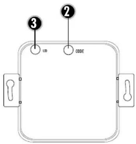
text_image
③ LED ② CODEExemple de raccordement 1
text_image
N 230 V/50Hz L Zuleitung Lüfter MExemple de raccordement 2
flowchart
graph TD
    A["STEUERMODUL ABLUFTGERÄT"] --> B["GND / Neutral"]
    A --> C["Stufe 1"]
    A --> D["Stufe 2"]
    A --> E["Stufe 3"]
    A --> F["Stufe 4"]
    B --> G["M"]
    D --> G
    E --> G
    F --> G
EMETTEUR DE POÊLE
text_image
Diagram of a mechanical or optical setup with labeled components and a magnified view showing internal components.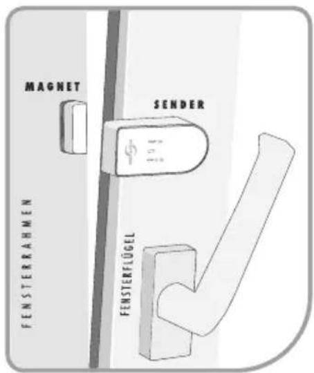
text_image
③ LED ② CODEAansluitvoorbeeld 1
text_image
N 230 V/50Hz L Zuleitung Lüfter MAansluitvoorbeeld 2
text_image
6a 6b 6c U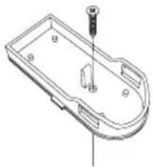
natural_image
Technical line drawing of a mechanical component with a screw and mounting holes (no text or symbols)
text_image
Diagram of a mechanical or electrical system with labeled components and connections, including numbered parts 4, 6, and U.