
AS-5120 - Uncategorized Protector - Free user manual and instructions
Find the device manual for free AS-5120 Protector in PDF.


| Product Type | Electronic Security Safe |
| Brand | Protector |
| Model | AS-5120 |
| Dimensions (H x W x D) | 35 x 25 x 25 cm |
| Weight | 10 kg |
| Power Supply | 4 x AA batteries (1.5V) |
| Locking Mechanism | Electronic keypad with backup key |
| Material | Solid steel body |
| Color | Black / Dark grey |
| Interior Capacity | 1.2 cubic feet |
| Functions | Digital code entry, programmable code, low battery indicator, alarm system |
| Security Features | Anti-tamper alarm, emergency override key, pry-resistant hinges |
| Installation | Floor or wall mounting; hardware included |
| Maintenance | Wipe with dry cloth; replace batteries annually |
| Contents Included | Safe, user manual, mounting bolts, emergency keys (2) |
Frequently Asked Questions - AS-5120 Protector
User questions about AS-5120 Protector
0 question about this device. Answer the ones you know or ask your own.
Ask a new question about this device
Download the instructions for your Uncategorized in PDF format for free! Find your manual AS-5120 - Protector and take your electronic device back in hand. On this page are published all the documents necessary for the use of your device. AS-5120 by Protector.
USER MANUAL AS-5120 Protector
natural_image
Technical line drawing of a mechanical component with a screw and mounting holes (no text or symbols)natural_image
Diagram of a mechanical assembly with stacked components and a top block (no text or symbols)CENTRAL UNIT (for socket)
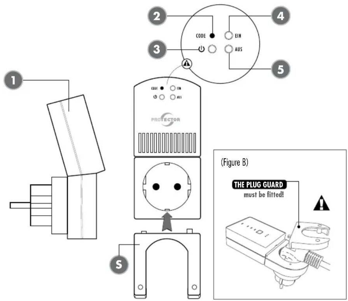
(1) Receiver
(2) CODE button
(3) Power LED
(4) LED Device Status ON
(5) LED Device Status OFF
(S) Plug Guard

Batteries and rechargeable batteries do not belong with household waste!
Every consumer is legally obliged to submit all batteries and rechargeable batteries to a collection point or retailer so that they can be disposed of in an environmentally friendly manner.
Please only submit discharged batteries and rechargeable batteries.
WINDOW TRANSMITTER
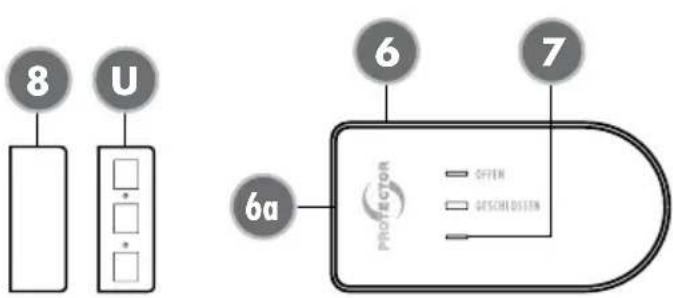
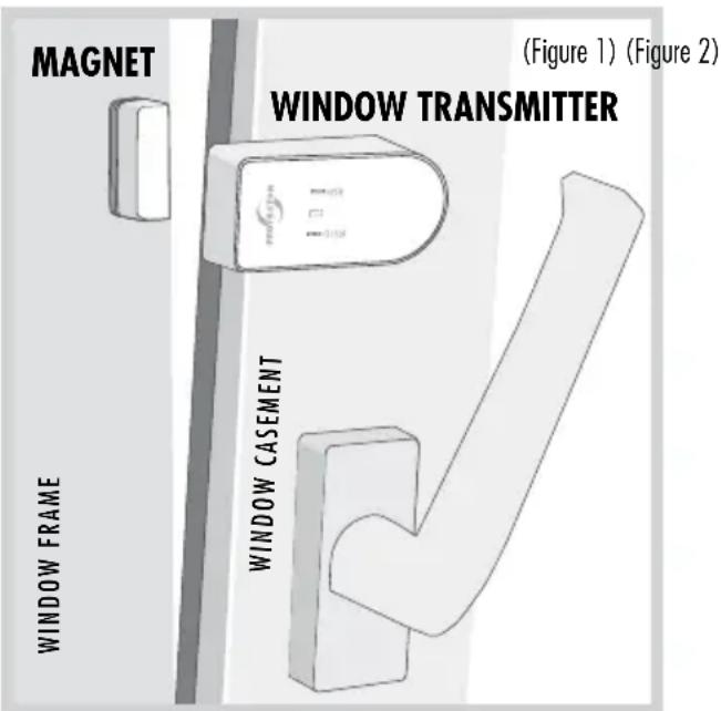
(6) Window Transmitter
(7) LED Status
(8) Magnet for Window Transmitter
(U) Washers
(Figure A)
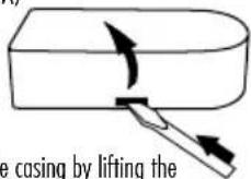
Open the casing by lifting the side with a screwdriver
(Figure C)
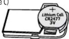
Insert battery with the "plus sign" facing up
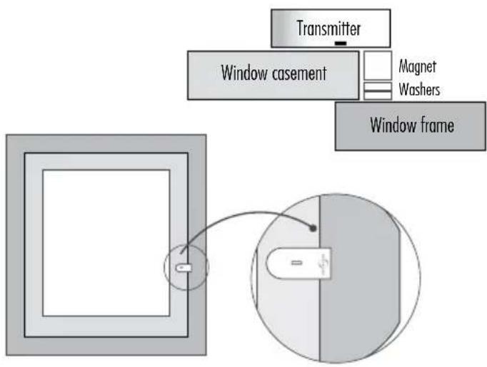
flowchart
graph TD
    A["Transmitter"] --> B["Window casement"]
    B --> C["Magnet"]
    B --> D["Washers"]
    B --> E["Window frame"]
    style A fill:#f9f,stroke:#333
    style B fill:#ccf,stroke:#333
    style C fill:#cfc,stroke:#333
    style D fill:#fcc,stroke:#333
    style E fill:#cff,stroke:#333
natural_image
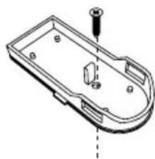
Technical line drawing of a mechanical component with a screw and mounting holes (no text or symbols)Mounting with enclosed adhesive pads or screws
natural_image
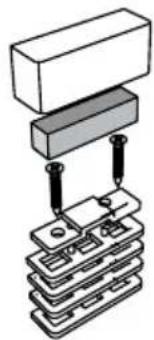
Diagram of a mechanical assembly with stacked components and a top block (no text or symbols)Casing cover
Magnet
Screws
Lower casing
Packer parts (optional)
You can mount the window sensor and magnet housing optionally with the enclosed adhesive pads or screws. If using one or more washers for the magnet housing, for example for compensating window frames, we recommend fastening the window transmitter and magnet housing with screws in order to prevent them from accidentally falling down.
Assembly and operating instructions for an exhaust air controller Model AS-5120 (radio version)
Thank you for purchasing the PROTECTOR AS-5120 Exhaust Air Controller.
GENERAL
This device can be used as an exhaust air control device, as an aid to monitor fresh air supply when commissioning an exhaust air device (fume extractor hood, fan etc...). This cannot replace self-monitoring to ensure fresh air supply, but it can be supportive. This device only activates the exhaust air system in the event of pressure equalisation when a window or door is opened. The additional fresh air streaming in can thus be drawn in from the outside.
You can also use this device to selectively switch devices or lamps ON or OFF, for instance when a door or a window is closed or opened. This, for example, enables significant reduction of energy costs for heating or air-conditioning devices.
ATTENTION
When using this device for exhaust air control, the shutter must be open to ensure adequate inflow of fresh air!
USE OF ADDITIONAL TRANSMITTERS (MAx. 6 DEVICES)
The device functionality can be extended by adding more transmitters (window contacts) with the result that the extractor hood is not limited to a single window only. Each individual transmitter can activate the exhaust air device.
FUNCTION SELECTOR SWITCH
You can select two functions (effective directions) with the sliding switch (1) of the receiver. In the (OPEN) switch position, the connected device is activated when a window is opened (e.g. for exhaust air control use). In the (CLOSE) switch position, the connected device (e.g. air-conditioner, heater) switches off when a window is opened.
i NOTE
As long as the receiver is plugged into the wall socket, a switching is not possible. To reverse the effective direction, the receiver must be removed from the socket, the switch be slid and the receiver be replaced into the socket.
RECEIVER INSTALLATION
Plug the AS-5120 receiver into a socket. Plug the device to be switched into the receiver socket and screw on the plug guard (S). The power LED (3) on the receiver is now on and the receiver is ready for use. In case the ON LED (4) and the OFF LED (5) flashes, please check the plug guard (S) for correct installation.

NOTE
The receiver should not be mounted behind a metal covering because this can limit the range.

ATTENTION
Always check that the power rating of the connected device is less than or equal to the switching capacity.
TRANSMITTER INSTALLATION
Preparation
Mount transmitter (2) and magnet (3) on the upper window frame and the window sash in such a way that the distance between the two housing components is less than 7 mm. Use the supplied washers (U) for adjustment.

NOTE
Please put the transmitter battery on the metal flap, do not slide it under the flap.
- Mount the transmitter housing base at the determined position, using the supplied double-sided adhesive pad.
Alternatively, there is a blanked hole in the bottom of the housing. Remove the circuit board from the bottom of the housing and carefully break open the hole. Use the hole to screw the transmitter to the window frame. Then replace the circuit board.
- Press the upper part of the housing onto its base.
- Mount the magnet housing bottom in the determined position, using the supplied adhesive pad.

ATTENTION
The distance between the transmitter and the magnet must not exceed 7 mm!
- Insert magnet and close with the housing cover.

NOTE
Assembly instructions for window contact Minimum window opening
These are based on:
a) The power of the exhaust air device in m^3/h
b) The size of the window to be opened in m^2
c) The size of the window opening in cm (see table 1)
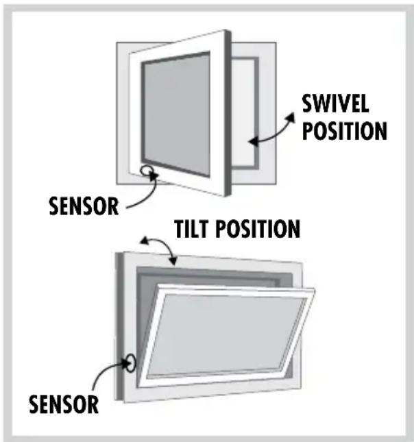
Most kitchens have rectangular tilt and pivot windows. If your window is round for example, please ask the installation and heating engineers or electrician to calculate the minimum opening. The minimum opening of rectangular windows is shown as an example in the table for the tilt
Calculation table to determine the minimum opening of your window
- Determine the extraction power of your exhaust air extraction device unit in m^3/h . You can find the exhaust air extraction power on the identification plate
Calculation table for the determination of the minimum opening on your window
(Table 1)
| WINDOW AREA IN M^2 | |||||||||||||||
| m^2 | 0,2 | 0,3 | 0,4 | 0,5 | 0,6 | 0,7 | 0,8 | 0,9 | 1 | 1,1 | 1,2 | 1,3 | 1,4 | 1,5 | |
| cm^2 | 2000 | 3000 | 4000 | 5000 | 6000 | 7000 | 8000 | 9000 | 10000 | 11000 | 12000 | 13000 | 14000 | 15000 | |
| MAXIMUM PERMITTED ExHAUST AIR PERFORMANCE IN M^3/H | |||||||||||||||
| Extent of window opening | 5 cm | 199 | 252 | 297 | 337 | 373 | 406 | 437 | 466 | 493 | 519 | 544 | 568 | 591 | 613 |
| 6 cm | 246 | 311 | 365 | 413 | 456 | 495 | 532 | 567 | 600 | 631 | 661 | 690 | 717 | 744 | |
| 7 cm | 294 | 369 | 432 | 488 | 538 | 585 | 628 | 668 | 707 | 743 | 778 | 811 | 843 | 874 | |
| 8 cm | 342 | 427 | 500 | 563 | 621 | 674 | 723 | 770 | 813 | 855 | 895 | 933 | 970 | 1005 | |
| 9 cm | 389 | 486 | 567 | 639 | 704 | 763 | 819 | 871 | 920 | 967 | 1012 | 1055 | 1096 | 1136 | |
| 10 cm | 437 | 544 | 635 | 714 | 786 | 852 | 914 | 972 | 1027 | 1079 | 1128 | 1176 | 1222 | 1266 | |
| 11 cm | 485 | 603 | 702 | 790 | 869 | 942 | 1009 | 1073 | 1133 | 1191 | 1245 | 1298 | 1348 | 1397 | |
| 12 cm | 532 | 661 | 770 | 865 | 951 | 1031 | 1105 | 1174 | 1240 | 1302 | 1362 | 1419 | 1475 | 1528 | |
or in the operating instructions of your exhaust air device (e.g. extractor hood).
- Measure the inner width and height of the window and calculate the window size in m^2 .
- Using the table, work out the opening size (minimum opening for your window) from the extraction power and window size.
- While the window is in the titled position, measure the upper inner gap size of the window in cm. The gap size of your window must not be below the opening size calculated! The bigger the gap or window opening, the better.
- If the gap size of the window is less than the permissible value for the opening size according to the table, the window may only be able to achieve the required opening size in the pivot position. There must also be a minimum gap when the window is in the pivoted position. The window contact shall be positioned in such a way as to ensure the minimum gap size. We recommend you ensure the minimum gap size using a spacer.
$$ \begin{array}{l} \text {(width x height = m^ {2} ; e.g. 0.8 m x 1.0 m = 0.8 m^ {2})} \ = \text {window size} \end{array} $$
CODING BETWEEN TRANSMITTER AND RECEIVER
The transmitter is not factory encoded and must be trained on the receiver when first operated.
i NOTE
Please follow sequence exactly!
- Open the casing of the transmitter (6) by sidely levering with a screwdriver. (see Figure A)
- Insert the plug of the device to be switched on (e.g. fume extractor hood) into the RECEIVER, and mount the plug guard (S)
i NOTE
Without the mounted plug guard the device will not function.
- Then plug the radio receiver into a mains socket. The „Power“ LED (3) lights up green and the „OFF“ LED (5) flashes red for 30 seconds if the radio receiver is functioning properly. During this time, the radio receiver is in learn mode and a radio transmitter can be tuned in.
- Within these 30 seconds, insert the battery CR2477 in the radio transmitter (6) with the correct polarity (the LED on the radio transmitter lights up briefly) and operate the radio transmitter by holding the magnet (8) once on the flat side of the radio transmitter (6a)
and removing it again. The LED built into the transmitter lights up. The „OFF“ LED (5) stops flashing on the radio receiver and the teach-in process is completed.
- Now the TRANSMITTER is tuned in to the RECEIVER and the AS-5120 is ready for use.
TUNING IN MORE THAN ONE TRANSMITTER (MAX. 6 DEVICES)
- Open the casing of the NEW transmitter (6) by sidely levering with a screwdriver. (see Figure A)
- Press the button (2) on the radio receiver for 3 seconds. The „OFF“ LED (5) starts flashing and the radio receiver is in learning mode for 30 seconds. During this time another radio transmitter can be tuned in to the radio receiver.
- Within these 30 seconds, insert the battery CR2477 in the NEW radio transmitter (6) with the correct polarity (the LED on the radio transmitter lights up briefly) and operate this radio transmitter by holding the magnet (8) once on the flat side of the radio transmitter (6a) and removing it again. The LED built into the transmitter lights up. The "OFF" LED (5) stops flashing on the radio receiver and the teach-in process is completed.
-
Repeat steps 1-3 for each individual transmitter.
-
Once a maximum of 6 TRANSMITTERS is tuned in, it is impossible to add any more.
DELETING ONE OR ALL TRANSMITTERS MAX. 6 DEVICES)
Deleting individual TRANSMITTERS
- Press the button (2) on the radio receiver for 3 seconds. The „OFF“ LED (5) starts flashing.
- Activate the radio transmitter to be deleted by holding the magnet (8) once on the flat side of the radio transmitter (6a) and removing it again. The „OFF“ LED (5) stops flashing on the radio receiver and the deletion process for the individual radio transmitter is completed.
Deleting all TRANSMITTERS
- Press the button (2) on the radio receiver for 3 seconds. The „OFF“ LED (5) starts flashing.
- Press the button (2) again for 3 seconds. The flashing of the LED „OFF“ (5) on the radio receiver stops and the deletion process for all radio transmitters is completed.
FUNCTIONAL TEST
With (OPEN) switch position:
-
Switch exhaust air device ON and open the window > exhaust air device must switch on.
-
Close the window > exhaust air device must switch off.
With (CLOSE) switch position:
-
Switch connected device ON and open the window > the connected device must switch off.
-
Close the window > the connected device must switch on.
mEANING OF LED DISPLAYs
RECEIVER / CENTRAL UNIT
LED Power (3)
Green permanent lighting > Ready for operation
OFF > Device fault or no power
LED-ON (4)
Green permanent light > Device status ON (window open)
LED-OFF (5)
Red permanent light > Device status OFF (window closed)
FLASHING > devices in teach mode
LED ON (4) and LED OFF (5)
Alternating flash > Plug guard is not plugged
Red and green permanent lighting >
Transmitter has been taught in successfully
WINDOW TRANSMITTER
OFF > Standby mode
Green flashing > window opens
Red flashing > window closes
Red 0.5 sec flashing > Window transmitter
battery empty
i mALFUNCTIONS
In individual cases cross-over with other similar radio devices can cause malfunctions. In the normal case it is sufficient to check the positioning of the components and if necessary, to modify this.
TECHNICAL DATA
Mains voltage: 230 V
\~, 50/60 Hz,
approx. 1 W
Mains switching capacity: 1000 W / 5A, at cos phi = 1
Radio range up to: 50 m
Frequency:
868,350 MHz
Transmitting power: < 10 mW
Protection class: IP 20 * only for dry rooms
Batterie (transmitter): 1 x 3V Lithium Typ
CR 2477 (lifetime approx.
3 years)
Never carry out repairs yourself!
2 YEAR LIMITED GUARANTEE
For two years after the date of purchase, the defect-free condition of the product model and its materials is guaranteed. This guarantee is only valid when the device is used as intended and is subject to regular maintenance checks. The scope of this guarantee is limited to the repair or reinstallation of any part of the device, and is only valid if no unauthorised modifications or attempted repairs have been undertaken. Customer statutory rights are not affected by this guarantee.
i Please note!
No claim can be made under guarantee in the following circumstances:
• Operational malfunction
• Empty batteries or faulty accumulator
• Erroneous coding/channel selection
• Fault through other radio installation
(i.e. mobile operation)
• Unauthorised modifications / actions
- Mechanical damage
- Moisture damage
• No proof of guarantee (purchase receipt)
Claims under warranty will be invalidated in the event of damage caused by non-compliance with the operating instructions. We do not accept any responsibility for consequential damage! No liability
will be accepted for material damage or personal injury caused by inappropriate operation or failure to observe the safety instructions. In such cases, the guarantee will be rendered void.
Liability limitation
The manufacturer is not liable for loss or damage of any kind including incidental or consequential damage which is the direct or indirect result of a fault to this product.
SAFETY NOTES
The warranty will be null and void in case of damages arising from violations of these operating instructions. We are not liable for consequential damages! We accept no liability for material damages or injuries arising from inappropriate use or violation of the safety instructions. In such cases all warranty claims are null and void!
Do not use this product in hospitals or other medical facilities. Although this device transmits only relatively weak radio signals, the signals may insuch locations result in malfunctioning of systems critical to life. The same may apply to other areas.
For reasons of safety and licensing (CE), unauthorised conversion and /or modification of the product is prohibited.
The design of the product complies with protection class 1. Only a standard mains socket (230V\~/50Hz) of the public mains supply may be used to power the device. Devices powered by mains voltage must be kept away from children. Please therefore be particularly careful in the presence of children.

ATTENTION
Do not take the product apart!
There is a danger of lethal electric shock!
Do not leave packaging material lying about since plastic foils and pockets and polystyrene parts etc. could be lethal toys for children.
The device is suitable only for dry interior rooms (not bathrooms and other moist places). Do not allow the device to get moist or wet. There is a danger of lethal electric shock!
These operating instruction are published by Protector GmbH
The operating instructions reflect the current technical specifications at time of print. We reserve the right to change the technical or physical specifications.
NOTES



- GENERAL
- ATTENTION
- FUNCTION SELECTOR SWITCH
- i NOTE
- RECEIVER INSTALLATION
- NOTE
- TRANSMITTER INSTALLATION
- Preparation
- Calculation table to determine the minimum opening of your window
- Calculation table for the determination of the minimum opening on your window
- CODING BETWEEN TRANSMITTER AND RECEIVER
- Please follow sequence exactly!
- Without the mounted plug guard the device will not function.
- TUNING IN MORE THAN ONE TRANSMITTER (MAX. 6 DEVICES)
- DELETING ONE OR ALL TRANSMITTERS MAX. 6 DEVICES)
- Deleting individual TRANSMITTERS
- Deleting all TRANSMITTERS
- FUNCTIONAL TEST
- With (OPEN) switch position:
- mEANING OF LED DISPLAYs
- RECEIVER / CENTRAL UNIT
- WINDOW TRANSMITTER
- i mALFUNCTIONS
- TECHNICAL DATA
- Never carry out repairs yourself!
- YEAR LIMITED GUARANTEE
- i Please note!
- Liability limitation
- SAFETY NOTES
- NOTES
Brand : Protector
Model : AS-5120
Category : Uncategorized