
AS-510 - Air conditioner Protector - Free user manual and instructions
Find the device manual for free AS-510 Protector in PDF.


| Product Type | Wireless exhaust air control device with window/door contact |
| Power Supply (Receiver) | 230 V AC, 50/60 Hz, approx. 1 W |
| Maximum Switching Capacity | 1800 W / 8 A (resistive load) |
| Radio Frequency | 433.92 MHz |
| Range | Up to 50 m in open air |
| Transmitter Battery | CR2032, lifespan approx. 1 year |
| Protection Rating | IP20 (dry rooms only) |
| Mounting | Receiver plugs into mains socket; transmitter and magnet attached to window with adhesive pads or screws |
| Control Type | Wireless, learn-mode pairing between transmitter and receiver |
| Application | Exhaust air control for fume hoods/fans or general switching based on window/door position |
| Compatible Devices | Exhaust hoods, fans, lights, air conditioners (load within switching capacity) |
| Maintenance | Replace transmitter battery annually; clean with dry cloth |
| Safety | Do not modify or open; keep away from children; use only in dry interiors |
| Warranty | 2 years limited guarantee against defects |
| Certifications | CE compliant |
Frequently Asked Questions - AS-510 Protector
User questions about AS-510 Protector
0 question about this device. Answer the ones you know or ask your own.
Ask a new question about this device
Download the instructions for your Air conditioner in PDF format for free! Find your manual AS-510 - Protector and take your electronic device back in hand. On this page are published all the documents necessary for the use of your device. AS-510 by Protector.
USER MANUAL AS-510 Protector
natural_image
Diagram of a smartphone rear panel showing internal components and battery casing (no text or symbols)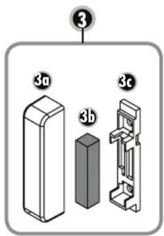

FENSTER GESCHLOSSEN
natural_image
Diagram of a smartphone showing internal components and battery casing (no text or symbols)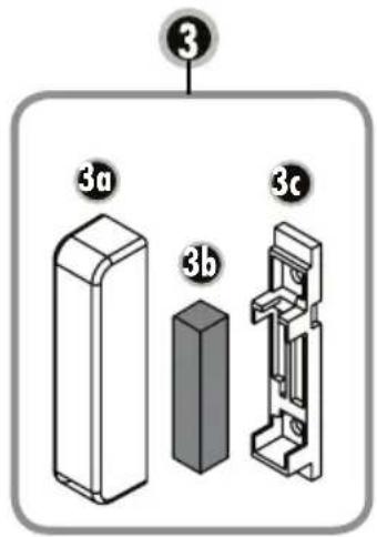

WINDOW CLOSED
WINDOW OPEN
RECEIVER
Assembly and operating instructions for exhaust control model AS-510 (wireless version)
Thank you for purchasing the PROTECTOR wireless exhaust control AS-510.

INTRODUCTION
The operating instructions are a constituent part of this device. They contain important notes on safety, use and disposal. Familiarise yourself with all operating and safety notes before using the equipment. Only use the article as described and for the listed areas of use. Pass all documents to the third party if you transfer the equipment to a new owner.
GENERAL
You can use this device as an exhaust air control device, as an aid to monitor fresh air supply when commissioning an exhaust air device (fume extractor hood, fan etc.). This cannot replace self-monitoring to ensure fresh air supply, but it can be supportive. This device only activates the exhaust air system in the event of pressure equalisation when a window or door is opened. The additional fresh air streaming in can thus be drawn in from the outside.
This device can also be used to selectively switch devices or lamps ON or OFF, for instance when a door or a window is closed or opened. This, for example, enables significant reduction of energy costs for heating or air-conditioning devices.

ATTENTION: When using this device for exhaust air control, the shutter must be open to ensure adequate inflow of fresh air!
KEY
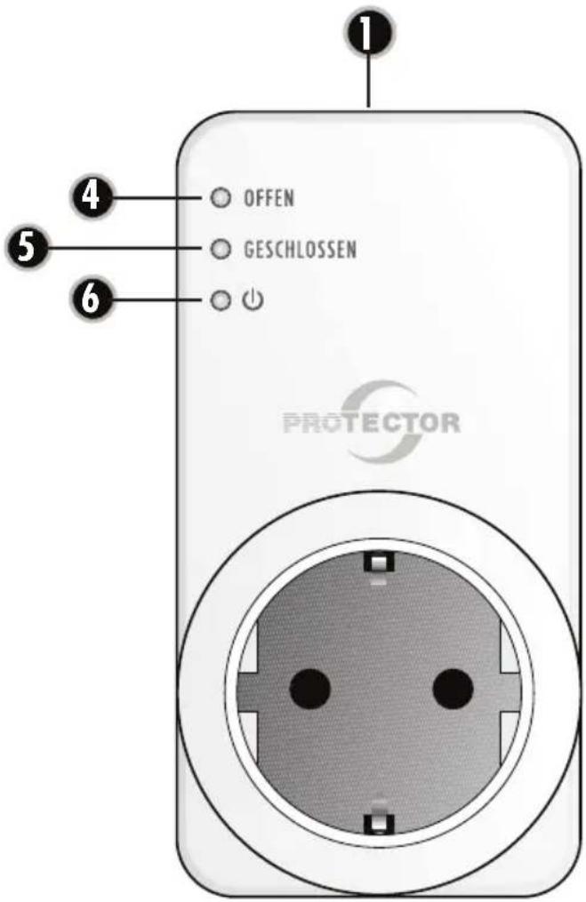
1 Base receiver
2 Window transmitter with reed contact
3 Magnet casing for window transmitter (3a,b,c)
U Packer parts
BASE (receiver)
4 LED base window open
5 LED base window closed
6 LED base network
TRANSMITTER
8 Transmission control LED
10 Battery compartment cover
MINIMUM OPENING ON WINDOW
This is determined by:
a. The throughput of the air extraction device in m^3/h
b. The size of the window to be opened in m^2
c. The size of the gap at the window in cm (see Table 1)
Most kitchens are equipped with rectangular combination tilt & turn windows.
If the window is, for example, round in form, then ask your specialist installation technician or the district flue & chimney inspector to calculate the minimum opening.
An example of the required minimum opening for a rectangular window is shown in the table for tilt/turn adjustment.
Calculation table to determine the minimum opening of your window (Table 1)
| Window area in m^2 | |||||||||||||||
| m^2 | 0,2 | 0,3 | 0,4 | 0,5 | 0,6 | 0,7 | 0,8 | 0,9 | 1 | 1,1 | 1,2 | 1,3 | 1,4 | 1,5 | |
| cm^2 | 2000 | 3000 | 4000 | 5000 | 6000 | 7000 | 8000 | 9000 | 10000 | 11000 | 12000 | 13000 | 14000 | 15000 | |
| Maximum permitted exhaust air performance in m^3/h | |||||||||||||||
| Extent of window opening | 5 cm | 199 | 252 | 297 | 337 | 373 | 406 | 437 | 466 | 493 | 519 | 544 | 568 | 591 | 613 |
| 6 cm | 246 | 311 | 365 | 413 | 456 | 495 | 532 | 567 | 600 | 631 | 661 | 690 | 717 | 744 | |
| 7 cm | 294 | 369 | 432 | 488 | 538 | 585 | 628 | 668 | 707 | 743 | 778 | 811 | 843 | 874 | |
| 8 cm | 342 | 427 | 500 | 563 | 621 | 674 | 723 | 770 | 813 | 855 | 895 | 933 | 970 | 1005 | |
| 9 cm | 389 | 486 | 567 | 639 | 704 | 763 | 819 | 871 | 920 | 967 | 1012 | 1055 | 1096 | 1136 | |
| 10 cm | 437 | 544 | 635 | 714 | 786 | 852 | 914 | 972 | 1027 | 1079 | 1128 | 1176 | 1222 | 1266 | |
| 11 cm | 485 | 603 | 702 | 790 | 869 | 942 | 1009 | 1073 | 1133 | 1191 | 1245 | 1298 | 1348 | 1397 | |
| 12 cm | 532 | 661 | 770 | 865 | 951 | 1031 | 1105 | 1174 | 1240 | 1302 | 1362 | 1419 | 1475 | 1528 | |
- Find out the air extraction throughput of your air extraction device in m³/h. You can find this on the type plate or in the manual for the air extraction device (e.g. air extraction hood).
- Measure the internal width and height of the window and work out the window size in m^2 . (width x height = m^2 ; e.g. 0.8 m x 1.0 m = 0.8 m^2 ) = window size
-
Read off the window gap size (minimum gap at side of your window) where the air extraction throughput and window size intersect on the table.
-
Measure the inner window gap size at the top in the tilt position in cm. The gap size of your window may not be less than the gap size obtained from the table. An even larger gap or window opening is preferable.
- If the window's gap size is less than the permitted value according to the table then it may be that the window can only achieve the required gap size in the turning position. Even in the turning position, a minimum gap size must be achieved. The window contacts must be mounted so that maintenance of the minimum gap size is assured. We recommend that the minimum gap size is fixed by means of a spacer.
RECEIVER ASSEMBLY
Insert the receiver for the AS-510 into a socket. Plug the equipment that you wish to switch into the receiver socket. The receiver is ready for operation as soon as the power LED (5) illuminates.

Note: The receiver should not be mounted behind metal cladding as this can limit range.

CAUTION: Always check whether the power input of the connected equipment is lower or equal to the switching capacity.
TRANSMITTER ASSEMBLY
Remove the battery compartment cover (10) by applying slight pressure and at the same time sliding it in the direction of the arrow.
Place the battery (CR2032) in correct pole direction (+ on top side) into the window transmitter. Close the battery compartment cover correctly.
Mount the window transmitter (2) at the window leaf on the window to be monitored. Make sure that the minimum gap opening dimension is taken into account (see „Minimum Opening on Window“).
-
To attach the window transmitter you can either use the two supplied adhesive pads or 2 screws, which are inserted through the two straps on the window transmitter and screwed into the window leaf. Before screwing the window transmitter, make sure that the position of the window transmitter is correct.
-
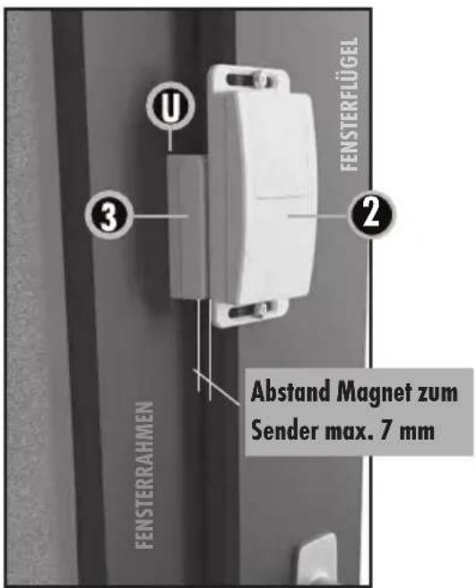
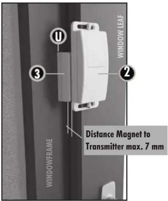
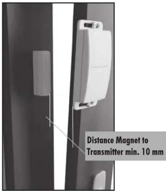
Attach the magnet housing (3) to the window frame
behind the window transmitter in such a way that the distance between the magnet housing and the window transmitter is no more than 7mm when the window is closed. The magnet housing can be attached to the window frame either with the enclosed adhesive pad or with a screw. To do this, open the magnet housing by levering out the bottom part (3c) with a suitable screwdriver.
-
If the magnetic housing is not close enough to the transmitter, you can reduce the distance by using the supplied packer parts (U).
-
After the packer parts and the bottom part of the magnet housing have been fixed, replace the magnet (3b) and then replace the upper housing part. Make sure that the upper part of the housing snaps into place correctly.
ENCODING EXHAUST CONTROL
The window transmitter is not encoded at the factory and needs to be programmed to the receiver during initial operation.

Please keep to the exact sequence!
- Insert the plug on the equipment to be switched (e.g. exhaust hood) into the RECEIVER.
- Then insert the RECEIVER into a mains socket. The power LED (6) flashes yellow if the RECEIVER is functioning correctly. The receiver is now in learning mode for 20 seconds.
- Insert the battery CR2032 into the window transmitter and slide the switch (11) into position „I“ to turn the device on.
- Activate the window TRANSMITTER by holding the magnet (3) against the transmitter (2) once and then removing it. The LED installed in the transmitter will
illuminate. The power LED (6) on the RECEIVER stops flashing and the programming process is complete.
- The TRANSMITTER has now been programmed to the RECEIVER and the AS-510 is ready for use.
- The receiver goes into learn mode for 20 seconds after every mains power failure. If no new window transmitter is taught then the old encoding remains.
FUNCTION TEST
- Switch the exhaust device ON and open the window
Exhaust device must start.
- Close window
Exhaust device must switch off.

MALFUNCTIONS
In isolated cases, faults may occur due to interference by other, similar radio units. It normally suffices if you check (and if necessary change) the location of the components.
TECHNICAL DATA
Mains voltage: 230 V
\~, 50/60 Hz,
approx. 1 W
Mains switching capacity: 1800 W / 8A, at cos phi = 1
Radio range up to: 50 m
Frequency: 433.92 Mhz
Protection class: IP 20 * only for dry rooms
Battery (transmitter): CR2032
(lifetime approx. 1 year)

Never carry out repairs yourself!
2 YEAR LIMITED GUARANTEE
For two years after the date of purchase, the defect-free condition of the product model and its materials is guaranteed. This guarantee is only valid when the device is used as intended and is subject to regular maintenance checks. The scope of this guarantee is limited to the repair or reinstallation of any part of the device, and is only valid if no unauthorised modifications or attempted repairs have been undertaken. Customer statutory rights are not affected by this guarantee.

Please note!
No claim can be made under guarantee in the following circumstances:
- Operational malfunction
• Empty batteries or faulty accumulator - Erroneous coding/channel selection
- Fault through other radio installation
(i.e. mobile operation)
• Unauthorised modifications / actions - Mechanical damage
- Moisture damage
• No proof of guarantee (purchase receipt)
Claims under warranty will be invalidated in the event of damage caused by non-compliance with the operating instructions. We do not accept any responsibility for consequential damage! No liability will be accepted for material damage or personal injury caused by inappropriate operation or failure to observe the safety instructions. In such cases, the guarantee will be rendered void.
Liability limitation
The manufacturer is not liable for loss or damage of any kind including incidental or consequential damage which is the direct or indirect result of a fault to this product.

Safety notes
The warranty will be null and void in case of damages arising from violations of these operating instructions. We are not liable for consequential damages!
We accept no liability for material damages or injuries arising from inappropriate use or violation of the safety instructions. In such cases all warranty claims are null and void!
Do not use this product in hospitals or other medical facilities. Although this device transmits only relatively weak radio signals, the signals may in such locations result in malfunctioning of systems critical to life. The same may apply to other areas.
For reasons of safety and licensing (CE), unauthorised conversion and /or modification of the product is prohibited.
The design of the base (receiver) complies with protection class 1. Only a standard mains socket (230V\~/50Hz) of the public mains supply may be used to power the device. Devices powered by mains voltage must be kept away from children. Please therefore be particularly careful in the presence of children.

Do not take the product apart! There is a danger of lethal electric shock!
Do not leave packaging material lying about since plastic foils and pockets and polystyrene parts etc. could be lethal toys for children.
The device is suitable only for dry interior rooms (not bathrooms and other moist places). Do not allow the device to get moist or wet. There is a danger of lethal electric shock!
In industrial institutions, the accident prevention regulations of the Association of Commercial Professional Associations for electrical installations and equipment must be observed. Please consult a specialist should you have doubts regarding the method of operation, the safety, or the connections of the device.
Handle the product with care – it is sensitive to bumps, knocks or falls even from low heights. These operating instruction are published by Protector GmbH, An den Kolonaten 37, 26160 Bad Zwischenahn/Germany
The operating instructions reflect the current technical specifications at time of print. We reserve the right to change the technical or physical specifications.

- Assembly and operating instructions for exhaust control model AS-510 (wireless version)
- INTRODUCTION
- GENERAL
- KEY
- BASE (receiver)
- TRANSMITTER
- MINIMUM OPENING ON WINDOW
- RECEIVER ASSEMBLY
- TRANSMITTER ASSEMBLY
- ENCODING EXHAUST CONTROL
- Please keep to the exact sequence!
- FUNCTION TEST
- MALFUNCTIONS
- TECHNICAL DATA
- Never carry out repairs yourself!
- YEAR LIMITED GUARANTEE
- Please note!
- Liability limitation
- Safety notes
Brand : Protector
Model : AS-510
Category : Air conditioner