AS-7030 - Air-conditioner Protector - Free user manual and instructions
Find the device manual for free AS-7030 Protector in PDF.
| Product type | Wireless ventilation control for air extraction system |
| Brand | Protector |
| Model | AS-7030 |
| Power supply (central control) | 230 V ~, 50/60 Hz, approx. 2 W |
| Max. switching power | 1800 W / 8 A (cos phi = 1) |
| Radio range | Up to 50 m |
| Radio frequency | 868,350 MHz |
| Protection class | IP20 (dry rooms only) |
| Battery for window transmitter (AS-F20) | 1 x CR2477 |
| Battery for stove transmitter (AS-T30) | 2 x AA / mignon / LR6 alkaline |
| Included components | Receiver (central control), window transmitter, thermal transmitter for stove pipe |
| Main functions | Wireless ventilation control, anti-depression safety, window opening monitoring, chimney temperature detection |
| Maintenance | Periodically check operation; clean temperature sensor if necessary |
| Safety | Mandatory retaining device; function test before commissioning; automatic stop if window closed |
| Warranty | 2 years (limited, subject to proper use) |
Frequently Asked Questions - AS-7030 Protector
User questions about AS-7030 Protector
0 question about this device. Answer the ones you know or ask your own.
Ask a new question about this device
Download the instructions for your Air-conditioner in PDF format for free! Find your manual AS-7030 - Protector and take your electronic device back in hand. On this page are published all the documents necessary for the use of your device. AS-7030 by Protector.
USER MANUAL AS-7030 Protector
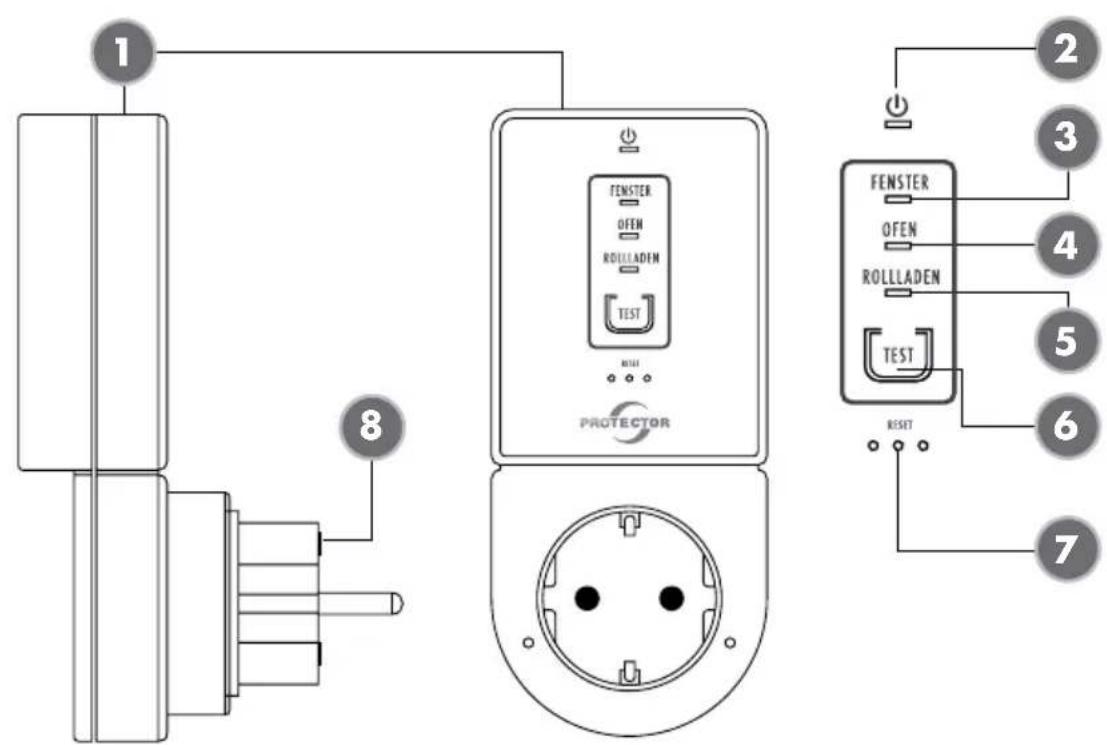
(3) Fenster-Sender LED
(4) Ofen-Sender LED
(5) Rollladen-Sender LED
(6) Test-Taste
natural_image
Technical line drawing of a mechanical component with a bolt and dashed centerline (no text or symbols)THERMO-SENDER
(1) Central unit (receiver)
(2) Power LED
(3) Window transmitter LED
(4) Stove transmitter LED
(5) Roller shutter transmitter LED
(6) Test button
(7) Reset button (paper clip)
(8) Microfuse 8A fast-acting
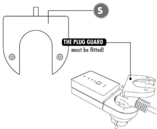
(S) Plug guard
text_image
THE PLUG GUARD must be fitted!WINDOW TRANSMITTER
text_image
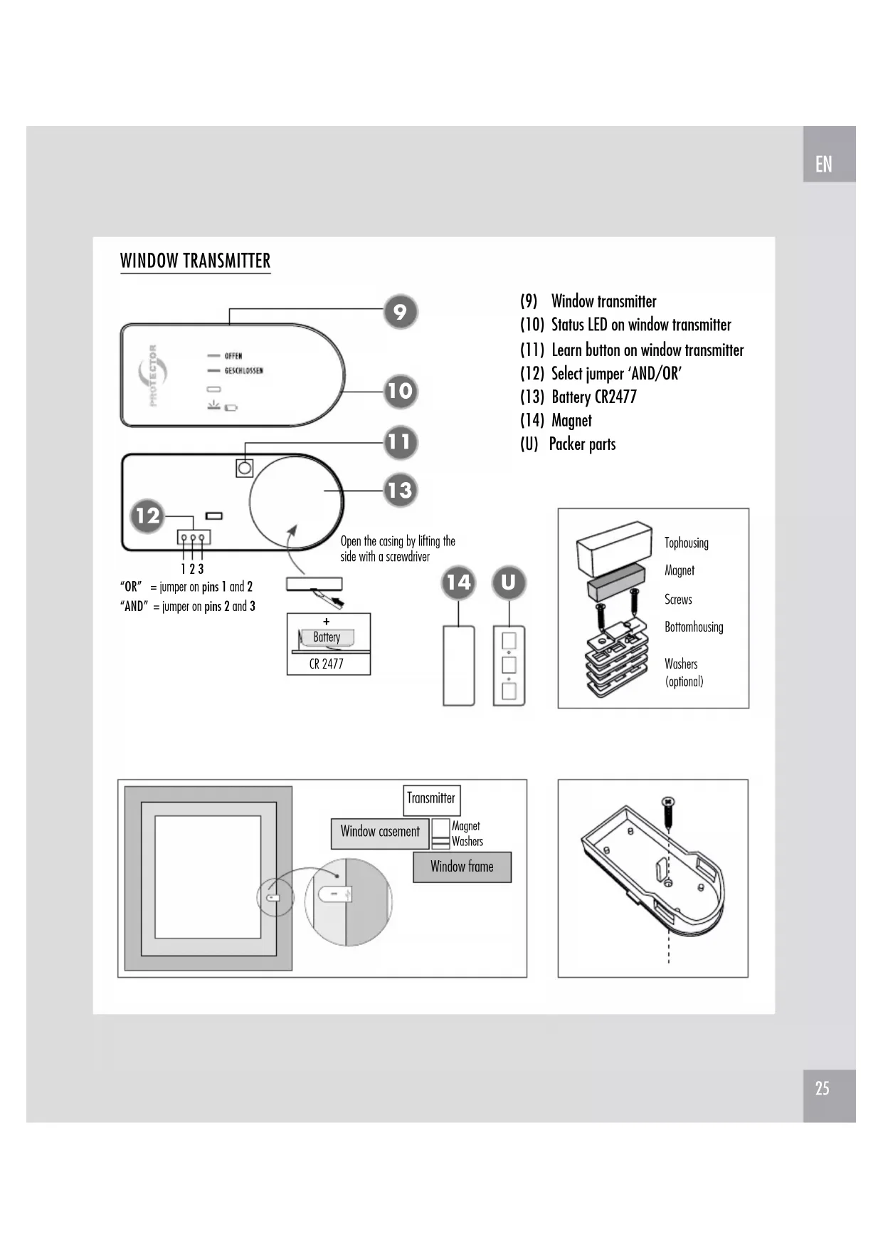
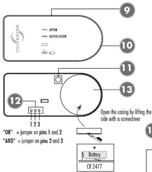
OFFEN GESCHLOSSEN 9 10 11 13 12 1 2 3 "OR" = jumper on pins 1 and 2 "AND" = jumper on pins 2 and 3 Open the casing by lifting the side with a screwdriver + Battery CR 2477(9) Window transmitter
(10) Status LED on window transmitter
(11) Learn button on window transmitter
(12) Select jumper 'AND/OR'
(13) Battery CR2477
(14) Magnet
(U) Packer parts
text_image
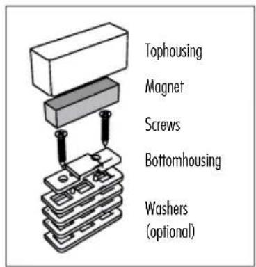
Tophousing Magnet Screws Bottomhousing Washers (optional)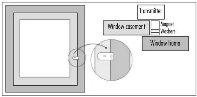
text_image
Transmitter Window casement Magnet Washers Window frame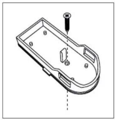
natural_image
Technical line drawing of a mechanical component with a screw and mounting holes (no text or symbols)THERMO TRANSMITTER
text_image
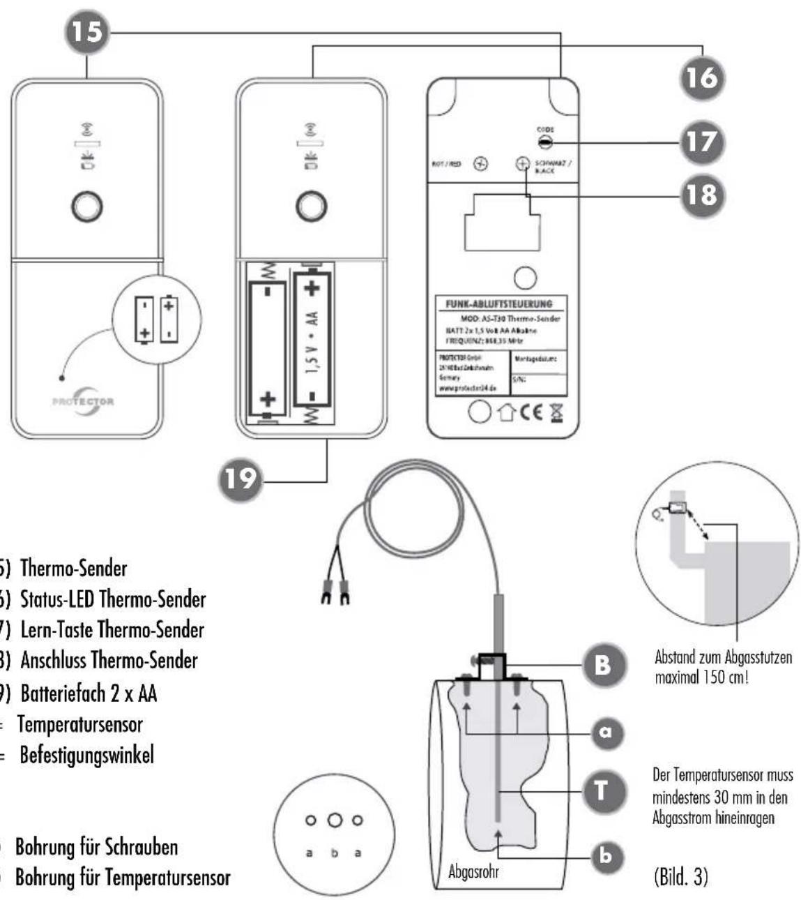
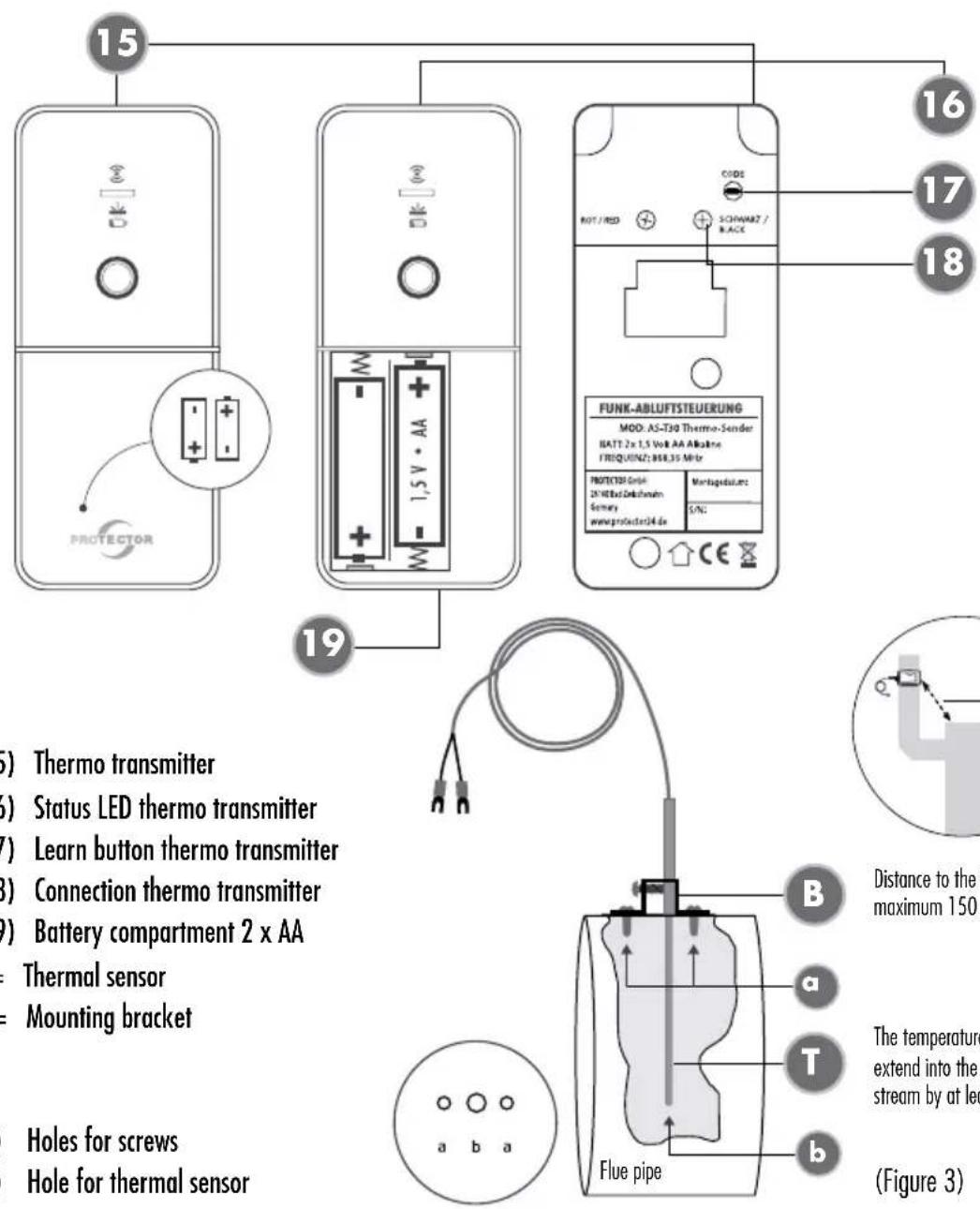
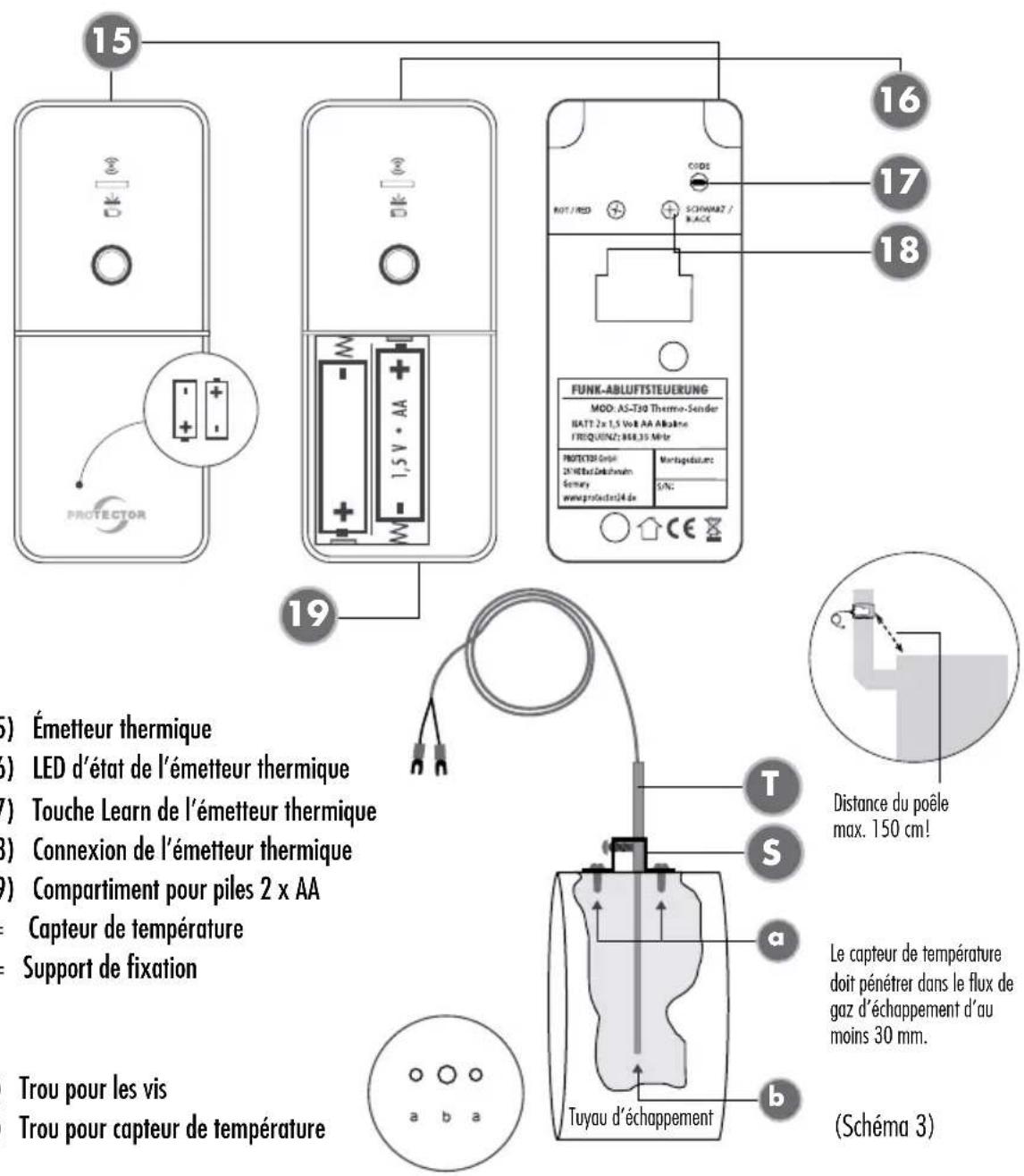
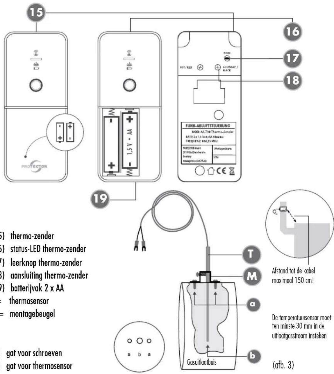
15 PROTECTOR 16 17 18 CODE NOT / RED SCHWARTZ / RACE FUNK-ABLUTSTEUERUNG MOD. AS-T30 Thermo-Sender BATT 2x 1,5 Volt AA Alkaline FREQUENZ: 868,35 Mio PROTECTOR GmbH 2X HEDz Gokkshum Sonomy www.protector34.de Montagedatum S/NC 19 (5) Thermo transmitter (6) Status LED thermo transmitter (7) Learn button thermo transmitter (8) Connection thermo transmitter (9) Battery compartment 2 x AA Thermal sensor Mounting bracket Holes for screws Hole for thermal sensor Distance to the maximum 150 a T Flue pipe b (Figure 3)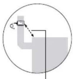
natural_image
Simple line drawing of a pipe junction with a magnified inset showing a small object (no text or symbols)Distance to the fireplace maximum 150 cm!
The temperature sensor must extend into the exhaust gas stream by at least 30 mm.
ROLLER SHUTTER TRANSMITTER
text_image
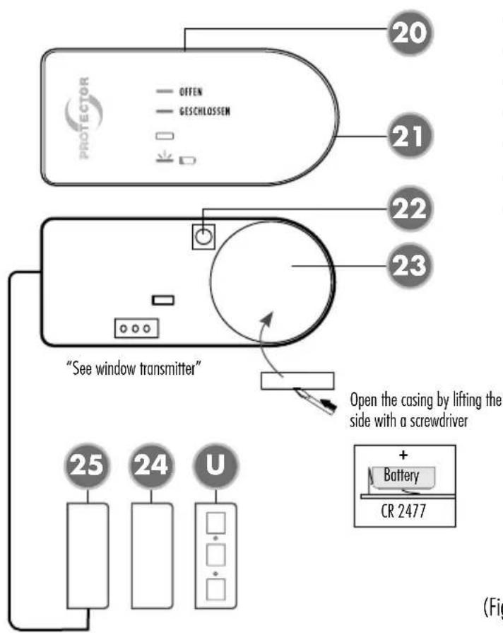
PROTECTOR OFFEN GESCHLOSSEN 20 21 22 23 "See window transmitter" Open the casing by lifting the side with a screwdriver 25 24 U + Battery CR 2477 (Fig(20) Roller shutter transmitter
(21) Status LED roller shutter transmitter
(22) Learn button on roller shutter transmitter
(23) Battery CR2477
(24) Magnet
(25) Roller shutter transmitter
(U) Packer parts
text_image
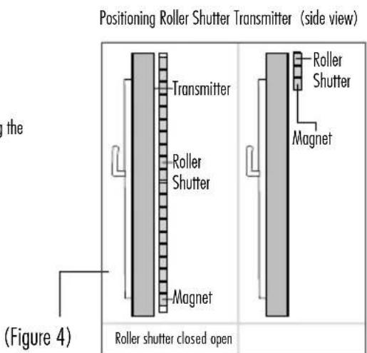
Positioning Roller Shutter Transmitter (side view) Transmitter Roller Shutter Magnet Roller Shutter Magnet Roller shutter closed open Figure 4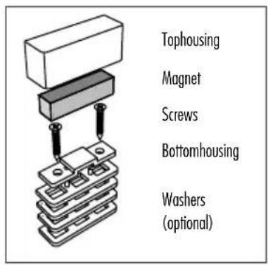
text_image
Tophousing Magnet Screws Bottomhousing Washers (optional)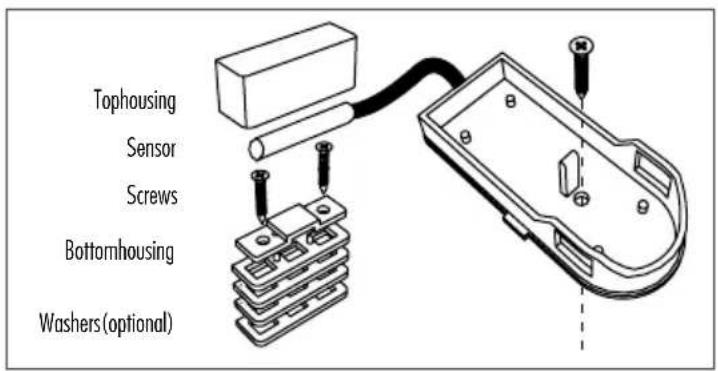
text_image
Tophousing Sensor Screws Bottomhousing Washers (optional)Thank you for purchasing the PROTECTOR wireless exhaust air controller in the AS-7000 series.
The operating instructions are a constituent part of the device. They contain important notes on safety, use and disposal. Familiarise yourself with all the operating and safety notes before using the device. Only use it as described and for the given areas of use. Pass on all the documentation if you transfer the device to a third party.
COMPONENTS INCLUDED
- Model AS-7020
1x receiver (central unit)
1x window transmitter
- Model AS-7030
1x receiver (central unit)
1x window transmitter
1x thermo-transmitter for stovepipe
- Model AS-7040
1x receiver (central unit)
1x window transmitter
1x thermo transmitter for stovepipe
1x roller shutter transmitter
GENERAL
The wireless exhaust air controller AS-7020/30/40 is used in connection with exhaust air systems such as an extractor hood, in rooms with access to an open fire, gas heater, open fireplace, tiled stove, wood stove, oil stove or similar.
Air is transported out of the room when using an exhaust air system, e.g. an extractor hood or exhaust air ventilators and this can cause negative pressure in closed rooms.
When combustible material is burned in an open fire this creates odourless and invisible carbon dioxide and carbon monoxide gases. These gases can enter the room from the fire when air is being removed with the help of an exhaust air system and this can lead to life-threatening poisoning in people in that room.
The exhaust air controller AS-7020/30/40 ensures that an exhaust air system can only be operated when fresh air is being supplied by an air supply system, e.g. an open window, sufficient replenishment of fresh air.
The exhaust air controller AS-7020/30/40 only switches the exhaust air device on if pressure equalisation is ensured. The plug guard connects the plug on the exhaust air device with the exhaust air controller and prevents inadvertent connection of the exhaust air device to an unprotected power source.
i NOTE
The teaching of the sensors (window transmitter, stove transmitter and roller shutter transmitter) in connection with the central unit must be carried out or tested before initial operation of the exhaust air controller. If the exhaust air controller is installed incompletely (e.g. without the relevant plug guard in figure S) or if it has been taught incorrectly before being connected to the socket a protect function will be activated and it will not be possible to operate the exhaust air system.
CAUTION!
The roller shutter must be open when the exhaust air device is in use or it must be fitted with an additional roller shutter sensor AS-R40. If the roller shutter is closed it is not possible to ensure sufficient replenishment of fresh air.
INSTALLATION
i NOTE
Note: Before installation, carry out the coding of the components and check the function of the exhaust air control (see page 38).
We recommend having the device installed by an installation technician and heating engineer or by an electrical installation technician. Correct installation guarantees the long term, safe operation of the exhaust air controller. The regional chimney sweep can and should carry out a function test.
Installation instructions
AS-7000 central unit (receiver) (fig. CENTRAL UNIT)
Please proceed as follows to install the receiver:
- Insert the power plug from the exhaust air device into the socket on the AS-7020/30/40 central unit.
- Attach the corresponding protective cap (S plug-guard) over the plug on the exhaust air device and screw it in place. If it is not possible to install the plug guard with the plug inserted then it may be necessary to adjust the edges of the plug guard slightly or to have an electrician attach a different plug.
- Connect the AS-7020/30/40 central unit to the power socket (power source). Following an internal self-test the power LED will light up green and operational readiness is signalled with a beep. (For further information on flashing and beeping patterns please see the status and error reports.)
Installation instructions for the window transmitter
AS-F20 and the magnet (9 and 14)
Some points need to be explained and followed in order to install the window transmitter and the magnet to the top window frame and to the window casements. The distance around all sides of the casing parts must be less than 6 mm and the minimum
Calculation table for the determination of the minimum opening on your window
(Table 1)
| Window area in m^2 | |||||||||||||||
| m^2 | 0,2 | 0,3 | 0,4 | 0,5 | 0,6 | 0,7 | 0,8 | 0,9 | 1 | 1,1 | 1,2 | 1,3 | 1,4 | 1,5 | |
| cm^2 | 2000 | 3000 | 4000 | 5000 | 6000 | 7000 | 8000 | 9000 | 10000 | 11000 | 12000 | 13000 | 14000 | 15000 | |
| Maximum permitted exhaust air performance in m^3/h | |||||||||||||||
| Extent of window opening | 5 cm | 199 | 252 | 297 | 337 | 373 | 406 | 437 | 466 | 493 | 519 | 544 | 568 | 591 | 613 |
| 6 cm | 246 | 311 | 365 | 413 | 456 | 495 | 532 | 567 | 600 | 631 | 661 | 690 | 717 | 744 | |
| 7 cm | 294 | 369 | 432 | 488 | 538 | 585 | 628 | 668 | 707 | 743 | 778 | 811 | 843 | 874 | |
| 8 cm | 342 | 427 | 500 | 563 | 621 | 674 | 723 | 770 | 813 | 855 | 895 | 933 | 970 | 1005 | |
| 9 cm | 389 | 486 | 567 | 639 | 704 | 763 | 819 | 871 | 920 | 967 | 1012 | 1055 | 1096 | 1136 | |
| 10 cm | 437 | 544 | 635 | 714 | 786 | 852 | 914 | 972 | 1027 | 1079 | 1128 | 1176 | 1222 | 1266 | |
| 11 cm | 485 | 603 | 702 | 790 | 869 | 942 | 1009 | 1073 | 1133 | 1191 | 1245 | 1298 | 1348 | 1397 | |
| 12 cm | 532 | 661 | 770 | 865 | 951 | 1031 | 1105 | 1174 | 1240 | 1302 | 1362 | 1419 | 1475 | 1528 | |
text_image
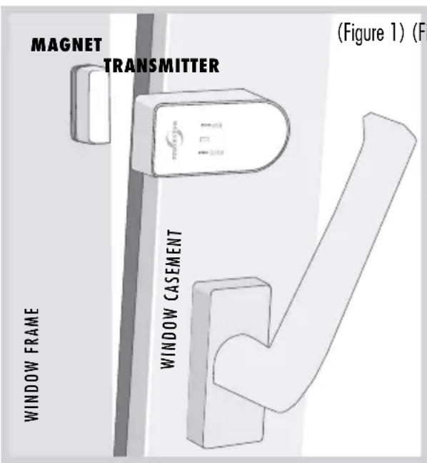
MAGNET TRANSMITTER (Figure 1) (F) WINDOW FRAME WINDOW CASEMENT(Figure 1) (Figure 2)
text_image
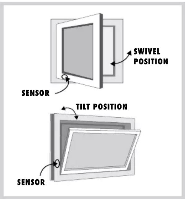
SWIVEL POSITION SENSOR TILT POSITION SENSORopening on the window (table 1) must be achieved. Please use the included packing parts (U) in order to adjust the height of the magnet.

NOTE
The window transmitter should not be installed directly on a metal window frame as this can reduce ranges.
PREPARATION
Minimum width of window opening
This is based on:
a) The performance of the exhaust air device in m^3/h
b) The size of the window to be opened in m^2
c) The size of the window opening in cm (see table 1)
Most kitchens have rectangular tilt and swivel windows. If you have windows that are, for example, round, then please ask the installation technician, heating engineer or electrician to calculate the minimum opening. The required minimum opening for the rectangular window can be found in the table for tilt and swivel windows as an example.
- Determine the exhaust air capacity of your exhaust air device in m^3/h . You can find the exhaust air capacity on the type plate or in the operating instructions for your exhaust air device (e.g. extractor hood).
- Measure the inside width and height of the window and calculate the window size in m^2 .
(Width x height = m²);
e.g. (0.8 m x 1.0 m = 0.8m²) = window size
- Determine the opening size (minimum opening of your window) from your exhaust air capacity and window size using the table.
- Measure the upper inside window opening gap in cm when tilted. The gap size on your window may not be less than the determined opening size! A larger gap or window opening is advantageous.
- If the gap size for the window is less than the permitted value for the window opening in accordance with the table, then the window may only be able to achieve the necessary opening when opened on swivel. A minimum gap size must also be achieved in the swivel position. The window transmitter must be attached in such a way that the minimum gap size is ensured. We recommend fixing the minimum gap size with the help of a distance piece.
Attaching the window transmitter
AS-F20 (figure 1)
i NOTE
Attach the window transmitter and the magnet to the window and the frame for the initial operation using double-sided sticky tape. Once the function test has been completed then the window transmitter and the magnet can be screwed in place.
This section describes attachment of the window transmitter for a tip and swivel window.
a) Attachment for the tilt position
The window transmitter and the magnet must be attached as shown in figure 2 TILT POSITION. The window transmitter must be attached near the hinge for the tilt position. The attachment point must be selected in such a way that a 'window open' signal is only produced once the necessary opening is achieved in accordance with the table.
b) Attachment for swivel position
The window transmitter and the magnet must be attached as shown in figure 2 SWIVEL POSITION. The window transmitter must be attached near the hinge for the swivel position. The attachment point must be selected in such a way that a 'window open' signal is only produced once the necessary opening is achieved in accordance with the table.
Proceed as follows to attach the window transmitter:
- Attach the lower casing section of the window transmitter at the correct position using the included double-sided sticky pad.
Alternatively there is a prepared hole in the lower casing section to screw the window transmitter onto the window frame. To use this carefully remove the printed circuit board from the lower casing section and screw the casing in place using the included screw. Then carefully replace the printed circuit board.
- Insert the battery (1x size CR2477) into the transmitter with the correct polarity and fix it in place.
i NOTE
Please ensure that you lay the battery in the window transmitter on top of the metal tab and not below it.
- Press the upper casing section onto the lower casing section.
Attaching the magnet
Fix the magnet in place in accordance with figure 1. Open and close the window once after attachment. The transmitter should flash at least once for each activation. Proceed as follows to attach the magnet:
-
Fix the lower magnet casing section at the correct position using the included double-sided sticky pad.
-
Insert the magnet and check the function of the window transmitter.
CAUTION!
The distance between the window transmitter and the magnet may not be more than 6 mm
-
Open the window again. The green LED (OPEN) should flash briefly if the transmitter is installed correctly.
-
Now close the window. The red LED (CLOSED) should flash briefly.
-
Once all the functions have been tested successfully the transmitter and the receiver must be screwed to the window/window frame. There is a prepared hole for this purpose on the lower casing section of the window transmitter and in the lower magnet casing section. These can be used to screw the window transmitter and the magnet to the window/window frame. This prevents the window transmitter and the magnet from falling down unintentionally.
-
Replace the magnet and close the magnet casing with the cover.
Attachment points:
- It must be ensured that the gap between the magnet and the contact is less than 6 mm when the window is closed.
- The contact must be attached to the upper or side window frame and casement in such a way that the distance between the two sections of the casing is less than 6 mm when the window is closed. Use the included packing (U) to adjust the parts for this purpose.
- We recommend attaching the contact and the magnet with the double-sided sticky tape before the final mounting and to only screw the elements in place at the end.
Testing the function of the window tilt and swivel position
- Slowly move the window to the tilt or swivel position, then the green LED on the window transmitter (OPEN) will flash briefly before the maximum tilt or swivel position.
- Close the window, then the red LED (CLOSED) will flash briefly.
- Finally check the opening gaps again using the minimum value determined in accordance with Table 1.
Attaching the roller shutter transmitter
AS-R40 (20 and 25)
i NOTE
Attach the roller shutter transmitter and the magnet to the window and the frame for the initial operation using double-sided sticky tape. Once the function test has been completed then the roller shutter transmitter and the magnet can be screwed in place
Attaching the roller shutter transmitter
The roller shutter transmitter and the magnet must be attached as shown in figure 4. The roller shutter transmitter must be attached to the inside of the window in the vicinity of the opened roller shutter. Alternatively the transmitter may also be attached between the window and the roller shutter but this will weaken the radio signal. The attachment point must be selected in such a way that a 'roller shutter
open' signal is only produced once the roller shutter is completely open.
Proceed as follows to attach the roller shutter transmitter:
- Mount the lower casing section of the roller shutter transmitter to the correct position using the included double-sided sticky pad.
Alternatively there is a prepared hole in the lower casing section to screw the roller shutter transmitter onto the window frame. To use this carefully remove the printed circuit board from the lower casing section and screw the casing in place using the included screw. Then carefully replace the printed circuit board.
- Insert the battery (1x size CR2477) into the transmitter with the correct polarity and fix it in place.
i NOTE
Please ensure that you lay the battery in the window transmitter on top of the metal tab and not below it.
- Press the upper casing section onto the lower casing section.
Attaching the magnet
Fix the magnet in place in accordance with figure 4. Open and close the roller shutter once after attachment. The transmitter should flash at least once for each activation. Proceed as follows to attach the magnet:
- Attach the lower magnet casing section and the lower sensor casing section in the correct position using the included double-sided sticky pad.
Alternatively there is a prepared hole in the lower casing sections through which the magnet and the sensor can be screwed to the window frame.
-
Drill a 5 mm hole through the window frame and feed the sensor cable to the outside into the lower casing section at the correct point.
-
Insert the magnet and the sensor and check the functioning of the roller shutter sensor.
CAUTION!
The distance between the roller shutter sensor and the magnet may not exceed 6 mm!
-
Open the roller shutter again. The green LED (OPEN) should flash briefly if the sensor has been installed correctly.
-
Now close the roller shutter. The red LED (CLOSED) will flash briefly.
-
After all functions have been successfully tested the transmitter, sensor and magnet must be screwed to the window/window frame. There is a prepared hole in the lower casing section of the roller shutter transmitter and in the lower casing of the magnet and sensor. This allows you to screw the roller shutter transmitter, magnet and sensor to the window/window frame. This prevents them from falling down unintentionally during operation.
-
Close the casing on the transmitter, the magnet and the sensor with the correct cover.
Attachment points:
- It must be ensured that the gap between the magnet and the sensor is less than 6 mm when the roller shutter is open.
- The contact must be attached to the top or side window frame and casement in such a way that the distance between the two casing sections is less than 6 mm when the window is closed! Use the included packing (U) to make these adjustments.
- We recommend attaching the contact and the magnet with the double-sided sticky tape before the final attachment and only to screw them in place at the end.
Testing the function of the roller shutter sensor
- Slowly move the roller shutter to the open position, then the green LED on the roller shutter sensor (OPEN) will flash briefly before the open position.
- Close the roller shutter, then the red LED (CLOSED) will flash briefly.
Instructions for attaching the stove transmitter
AS-T30 (15 and T)
i NOTE
The stove should be switched off and cool in order to avoid burns to your skin.
The distance between the installation point of the temperature measuring device and the exhaust stack of the room air-dependent fireplace in the connecting piece must not exceed a maximum of 1.5 m. The temperature sensor must extend into the exhaust gas stream by at least 30 mm and a maximum of 100 mm, whereby a homogeneous flow around the temperature sensor by the core flow of the exhaust gas must be ensured. Regular inspection and, if necessary, cleaning must be carried out.
The thermal sensor (figure 3) is fed into the exhaust pipe through a hole and screwed to the stove pipe using the included mounting bracket. The stove transmitter should not be covered by cladding as this impedes the radio signal and reduces the range.
- Drill a 4 mm hole in a suitable position in the exhaust pipe for the thermal sensor. If possible ensure that the hole is positioned in such a way that the thermal sensor cannot be seen after attachment.
-
Slide the mounting bracket over the thermal sensor but do not tighten the screw to attach the thermal sensor yet.
-
Insert the thermal sensor as far as possible into the hole that you have drilled for it.
- Move the mounting bracket on the thermal sensor until it is lying on the exhaust pipe and then mark the two attachment holes on the mounting bracket with a suitable pen. Then remove the thermal sensor and the mounting bracket from the exhaust pipe again.
- Drill 2 mm holes at the two positions you have marked for mounting on the exhaust pipe.
i NOTE
If you have a double-walled exhaust pipe then take care to drill the mounting holes only through the outer pipe.
- Fix the mounting bracket to the exhaust pipe by screwing it with the two included tapping screws and the two drilled holes as described above.
- Now feed the thermal sensor through the mounting bracket as far as possible and fix it to the mounting bracket using the side screw. Do not tighten the screw too far to avoid damage to the thermal sensor.
- Lay the wire to the stove transmitter.
-
Connect the wire on the thermal sensor to the stove transmitter and the wire marked in red to the screw ROT / RED and the wire marked in black to the screw SCHWARZ / BLACK.
-
There is a wall mount on the back of the stove transmitter. This can be pushed down and removed from the stove transmitter.
- Remove the cover from the stove transmitter and insert the 2 x AA batteries with the correct polarity as marked. Then you can slide the cover back on.
- Look for a suitable location to attach the stove transmitter and screw the wall bracket for the transmitter into place. The stove transmitter should be at least 50 cm away from the exhaust pipe so that the transmitter cannot be destroyed by heat. Also the stove transmitter should not be attached behind cladding as this limit its range.
INITIAL OPERATION
Before you start encoding, the jumpers of the window transmitter must be set correctly. If only one window transmitter is used, the jumper must be set in position "OR". If several window transmitters are to be used, they can be either AND-linked (each window must be open) or OR-linked (one of the windows must be open).
In case of AND connection, the jumper of the first window transmitter must be set in position "AND", the last in position "OR".
With an "OR" link, the jumper must be in the "OR" position for all window transmitters.
Jumper position see figure WINDOW TRANSMITTERS, point 12.
BRIEF INSTRUCTIONS
Factory settings
▶ Press and hold the reset button (see fig. CENTRAL UNIT, point 7)
The unit will beep once after approx. 1 second and 4 green LEDs will flash.
There will be 3 beeps after another 7 seconds followed by a pause and 3 more beeps. The power LED will light constantly
▶ Release the reset/learn button; the device is now set to default
Teaching the sensors:
(All the sensors to be taught are ready for operation)
- Make sure that the jumper for AND/OR connection is set correctly for each transmitter.
- Briefly press the reset button on the central unit (fig. CENTRAL UNIT, point 7).
- Briefly press the learn button on the first sensor.
-
After approx. 10 seconds, the corresponding LED lights up constantly depending on the sensor and the central unit emits a beep.
-
Briefly press the learn button on the next sensor (e.g. if this is a second window contact, the central unit emits two beeps, with the third window contact 3 beeps, etc.).
- Wait approx. 50 seconds after the last sensor, the central unit then ends the learning process and displays the status of the sensors via the LEDs.
The central unit and the transmitters are now ready for operation.
LED indications:
| Window closed | Window LED red |
| Window open | Window LED green |
| Stove on | Stove LED red |
| Stove off | Stove LED green |
| Roller shutter closed | Roller shutter LED red |
| Roller shutter open | Roller shutter LED green |
The relay will only switch if:
With window contact only:
Window open
With window and stove contact:
Stove off
▶ Stove on and window open
With window and roller shutter and stove contact:
Stove off
▶ Stove on, window and roller shutter open
DETAILED INSTRUCTIONS
Press the reset/learn button (see fig. CENTRAL UNIT, point 7) and hold it down for 10 s in order to delete all the learned transmitters. The reset routine is shown with a single beep as an acoustic signal and functions correctly if all the LEDs are flashing green.
If only the power LED is flashing green then the table definitely needs to be deleted, which is initiated by keeping the reset button depressed again. The central unit will respond with 2 acoustic signals, a pause and another 2 acoustic signals and the power LED will be reset to being lit constantly.
Release the reset button again after these signals. The sensor table and the corresponding flash memory in the device have now been deleted. This is shown by the constant lighting of the power LED. None of the corresponding sensor LEDs should be lit.
Encoding
The following steps are necessary to teach the relevant sensors:
Pairing can now be initiated by briefly pressing the reset/learn button. This is shown by a short acoustic signal and all the LEDs flashing green.
The transmitters are now paired individually.
The set button on each sensor is activated and this is answered by the sensor by flashing red-green. (The same LED signal is also displayed when the SET routing is running)
After approx. 10 seconds the LEDs on the central unit display which sensor type was taught and one or several acoustic signals will sound again in accordance with the number of sensors that have already been taught.

CAUTION!
An AND-linking of the sensors is created by setting the jumper in AND position for all transmitters except the last one. The jumper of the last transmitter must be set to the OR position.
Completion of the teach-in process has failed if the last transmitter to be taught-in is set with the jumper in the AND position and then a furnace transmitter is to be taught-in. The control unit then reports an error (3 short beeps, 3 long beeps, 3 short beeps) and the teach-in process must be repeated completely.
When this is done, you can configure another sensor or just wait, the learning process is automatically terminated 50 seconds after the last configured transmitter. This is shown by 2 consecutive acoustic triple signals and a change of the power LED to constant green and the corresponding sensor LED to the relevant status.
The exhaust air control is now installed and functional.
When operating the system please note that the window and roller shutter sensors have transferred their status to the central unit if they flash green twice after approx. 5 seconds. If the relevant sensor flashes red twice then the status was not transferred sufficiently and is sent in cycles again every 50 seconds until the status is accepted and confirmed as described above.
For the stove sensor the status is requested every 180 seconds. If the status of the stove sensor changes then it is updated to the central unit in accordance with the routine described above. The central unit decides on the release of the relays depending on the status of the taught-in transmitters.
System function test
Example AS-7020/30/40 and AS-F20 window transmitter)
- Switch the exhaust device on and open the window. The green LED flashes briefly and the green LED on the receiver is now on constantly. The exhaust device is switched on.
- Close the window and the exhaust device will switch off. The red LED on the transmitter flashes and the red LED on the receiver is now on constantly. The exhaust device is switched off.
- Your system is ready for operation once this function test has been completed. Repeat this function test at regular intervals for your own safety.
Status and error messages Versions AS-7020 / AS-7030 / AS-7040
| Status | Heater-Transmitter | Window-Transmitter | Jalousie-Transmitter | Central (acoustics) | Central (LED) | Central (relay) |
| AS-7020 | ||||||
| Window open | x Non-existent | 1x flash slowly GN After correct feedback 2x rapidly flashes | x Non-existent | — | LED window permanent GN | Power circuit closed |
| Window closed | x Non-existent | 1x flash slowly RD After correct feedback 2x rapidly flashes | x Non-existent | 1x Beep — | LED window permanent RD | Power circuit open |
| All | x Non-existent | 3x flash rapidly. New communication attempt. Central not reached, after 3 attempts stopping communication | x Non-existent | — | — | — |
| Battery warning | x Non-existent | — | x Non-existent | — | If window open permanent GN with flashing RD. If window closed, flashing RD. | Relay according to the state (please refer window open/closed) |
| Battery empty | x Non-existent | — | x Non-existent | — | LED Power flashes RD. Flashing status LED window RD | Power circuit open |
| AS-7030 | ||||||
| Window open | — | 1x flash slowly GN After correct feedback 2x rapidly flashes | x Non-existent | — | LED window permanent GN | Power circuit closed |
| Window closed | — | 1x flash slowly RD After correct feedback 2x rapidly flashes | x Non-existent | 1x beep if heater on | LED window permanent RD | Power circuit open, if heater on |
| Heater off | 1x flash slowly GNAfter correct feedback2x rapidly flashes(3 min. test interval) | — | xNon-existent | — | LED heater permanent GN | Power circuit closed |
| Heater on | 1x flash slowly RDAfter correct feedback2x rapidly flashes(3 min. test interval) | — | xNon-existent | 1x beep if window closed | LED heater permanent RD | Power circuit open, if window closed |
| All | — | 3x flash rapidly.New communication attempt.Central not reached, after 3 attempts stopping communication | xNon-existent | — | — | — |
| Battery warning | — | — | xNon-existent | — | If heater/window on/open permanent GN with flashing RD.If heater/window off/closed flashing RD. | Relay according to the state (please refer window open/closed) |
| Battery empty | — | — | xNon-existent | — | Power LED flashing RD.Flashing Status LED heater/window RD | Power circuit open |
| AS-7040 | ||||||
| Window open | — | 1x flash slowly GNAfter correct feedback2x rapidly flashes | — | — | LED window permanent GN | Power circuit closed |
| Window closed | — | 1x flash slowly RDAfter correct feedback2x rapidly flashes | — | 1x beep if heater on | LED window permanent RD | Power circuit open, if heater on and blinds closed |
| Heater off | 1x flash slowly GNAfter correct feedback2x rapidly flashes(3 min. test interval) | - | - | - | LED heater permanent GN | Power circuit closed |
| Heater on | 1x flash slowly RDAfter correct feedback2x rapidly flashes(3 min. test interval) | - | - | 1x beep if window closed | LED heater permanent RD | Power circuit open, if window and blinds closed |
| Blinds open | - | - | 1x flash slowly GNAfter correct feedback2x rapidly flashes | - | LED blinds permanent GN | Power circuit closed |
| Blinds closed | - | - | 1x flash slowly RDAfter correct feedback2x rapidly flashes | 1x beep if blinds closed | LED blinds permanent RD | Power circuit open, if heater on |
| All | - | 3x flash rapidly.New communication attempt.Central not reached, after 3 attempts stopping communication | - | - | - | - |
| Battery warning | - | - | - | - | If heater on/window open/blinds open GN with flashing RD.Otherwise flashing RD. | Relay according to the state (please refer window open/closed) |
| Battery empty | - | - | - | - | POWER LED flash RDFlashing Status LED Heater/window/blinds RD | Power circuit open |
Note
The functionality of the unit can be affected by the influence of strong static, electrical or high frequency fields (discharging, mobile phones, radios, microwaves).
CE Conformity
We confirm device conformity in accordance with the European guideline 89/336/EEC for electromagnetic compatibility and with the low voltage guideline 73/23/EEC. Radio approval is certified in accordance with the EC R&TTE directive 1995/5/EC.
Technical data
Network voltage (central unit):
230 V \~, 50/60 Hz, approx.
2 W switching capacity: 1800 W, 8A, at cos phi=1
Radio range: up to 50 m
Radio frequency: 868.350 MHz
Protection class: IP 20, only for dry rooms
Batteries:
(Window transmitter AS-F20): 1 x size CR2477
(Roller shutter sensor AS-R40): 1 x size CR2477
Batteries (stove transmitter AS-T30):
2 x size AA/mignon/LR6 alkaline
Safety notes
The warranty will be null and void in case of damages arising from violations of these operating instructions. We are not liable for consequential damages!
We accept no liability for material damages or injuries arising from inappropriate use or violation of the safety instructions. In such cases all warranty claims are null and void!
Do not use this product in hospitals or other medical facilities. Although this device transmits only relatively weak radio signals, the signals may in such locations result in malfunctioning of systems critical to life. The same may apply to other areas.
For reasons of safety and licensing (CE), unauthorised conversion and /or modification of the product is prohibited.
Never carry out repairs yourself! Do not take the product apart! There is a danger of lethal electric shock!
Do not leave packaging material lying about since plastic foils and pockets and polystyrene parts etc. could be lethal toys for children.
The device is suitable only for dry interior rooms (not bathrooms and other moist places). Do not allow the device to get moist or wet.
In industrial institutions, the accident prevention regulations of the Association of Commercial Professional Associations for electrical installations and equipment must be observed. Please consult a specialist should you have doubts regarding the method of operation, the safety, or the connections of the device.
Handle the product with care — it is sensitive to bumps, knocks or falls even from low heights.
2 YEAR LIMITED GUARANTEE
For two years after the date of purchase, the defect-free condition of the product model and its materials is guaranteed. This guarantee is only valid when the device is used as intended and is subject to regular maintenance checks. The scope of this guarantee is limited to the repair or reinstallation of any part of the device, and is only valid if no unauthorised modifications or attempted repairs have been undertaken. Customer statutory rights are not affected by this guarantee.
Please note!
No claim can be made under guarantee in the following circumstances:
- Operational malfunction
• Empty batteries or faulty accumulator - Erroneous coding/channel selection
- Fault through other radio installation (i.e. mobile operation)
• Unauthorised modifications / actions - Mechanical damage
- Moisture damage
- No proof of guarantee (purchase receipt)
Claims under warranty will be invalidated in the event of damage caused by non-compliance with the operating instructions. We do not accept any responsibility for consequential damage! No liability will be accepted for material damage or personal injury caused by inappropriate operation or failure to observe the safety instructions. In such cases, the guarantee will be rendered void.
Liability limitation
The manufacturer is not liable for loss or damage of any kind including incidental or consequential damage which is the direct or indirect result of a fault to this product.
These operating instruction are published by
Protector GmbH
An den Kolonaten 37
The operating instructions reflect the current
technical specifications at time of print.
We reserve the right to change the technical or
physical specifications.
COMMANDE CENTRALE
text_image
1 8 FENSTER OFEN ROLLLADEN TEST PROTECTOR FENSTER OFEN ROLLLADEN TEST RESET 2 3 4 5 6 7natural_image
Technical line drawing of a mechanical component with a screw and mounting holes (no text or symbols)ÉMETTEUR THERMIQUE
natural_image
Diagram of a mechanical assembly with stacked components and a block, no text or symbols presentnatural_image
Technical line drawing of an electronic device with a battery, housing, and wiring (no text or symbols)natural_image
Technical line drawing of a mechanical component with a screw and mounting holes (no text or symbols)THERMO-ZENDER
natural_image
Diagram of a layered electronic component with pins and a rectangular block (no text or symbols)natural_image
Technical line drawing of an electronic device with a cable and housing, showing components like a battery pack and socket (no text or symbols)text_image
CE interseroh