Grand Tour - Bike trailer Axkid - Free user manual and instructions
Find the device manual for free Grand Tour Axkid in PDF.

| Product type | Convertible bicycle trailer into stroller (buggy/jogger) |
| Brand | Axkid |
| Model | Grand Tour |
| Number of children | Up to 2 children |
| Minimum age | 6 months (child able to sit unaided) |
| Maximum child weight | 22 kg per child |
| Maximum cargo load | 6 kg |
| Tongue load | Between 3 and 8 kg |
| Recommended maximum speed | 16 km/h (10 km/h in turns and bumpy roads) |
| Restraint system | Adjustable 5-point harness |
| Brake | Parking brake on handlebar, acting on both rear wheels |
| Recommended tire pressure | 30-35 PSI |
| Wheel types | Rear wheels with reflectors; jogging wheel and buggy wheels optional |
| Included accessories | Tongue with hitch, safety flag, protective cover |
| Frame material | Steel (unspecified, estimated) |
| Product weight | Approximately 12 kg (estimated) |
| Dimensions (L x W x H) | Approximately 110 x 70 x 90 cm (estimated for a 2-seat trailer) |
| Maintenance | Clean with warm water and mild soap; lubricate moving parts; regularly check for wear |
| Storage | In a dry place, out of direct sunlight |
| Certification | Compliant with European safety requirements (estimated) |
Frequently Asked Questions - Grand Tour Axkid
User questions about Grand Tour Axkid
0 question about this device. Answer the ones you know or ask your own.
Ask a new question about this device
Download the instructions for your Bike trailer in PDF format for free! Find your manual Grand Tour - Axkid and take your electronic device back in hand. On this page are published all the documents necessary for the use of your device. Grand Tour by Axkid.
USER MANUAL Grand Tour Axkid
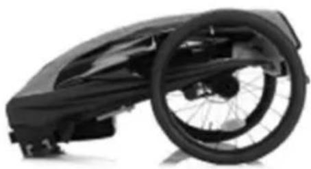
natural_image
Line drawing of a two-wheeled vehicle with a wheel and side-mounted frame (no text or symbols)
IMPORTANT! READ CAREFULLY AND KEEP FOR FUTURE REFERENCE.
Read these instructions carefully before assembling and using the product.
The assembly may only be carried out by an adult.
Retain these instructions for future reference.
Contents
Warnings....2
Components......4
Assembling the base frame....5
Folding the base frame....6
Use of the safety belt....7
Attaching the rear wheels....8
Set and release the parking brake....9
Attaching the drawbar (bicycle trailer configuration) 10
Mounting the axle coupling (quick release)....11
Assembly of the axle coupling (solid axle)....13
Attaching the safety pennant (bicycle trailer configuration)....14
Coupling the trailer to the bicycle (bicycle trailer configuration)....15
Mounting the buggy wheels (buggy configuration)....16
Mounting the jogger wheel (jogger configuration)....17
Adjust the positions of wheel suspension....18
Care & Maintenance....18
Not following the instructions and safety information in this manual can result in serious injury or death to the passenger or driver!
• Any additional load on the handlebar will affect the stability of the trailer.
- Do not use this trailer on stairs or escalators.
- Do not transport additional children or bags with this trailer.
- Never leave the child unattended.
- Be careful not to pinch your fingers when folding and unfolding this child carrier. Make sure your child is not nearby when folding and unfolding this product to avoid injury.
• Make sure that the child's limbs, clothing, laces, or toys do not come into contact with moving parts of the van.
- Do not install a car seat or other seating device.
- The maximum load for one kid is 22 kg.
- The maximum load of the luggage compartment is 6 kg.
• The parking brake must always be applied while children are getting in and out.
• Always wear a helmet that complies with local regulations.
- Never ride at night without proper lighting. Follow all locally applicable legal requirements regarding lighting.
- Be extremely careful when driving with the trailer. Do not drive faster than 16 km/h and slow down to less than 10 km/h when cornering and on bumpy roads.
- The drawbar load should not be less than 3 kg and not exceed 8 kg.
• Always fasten the safety catch strap of the hitch. Do not use the bicycle trailer if you cannot attach the safety strap to the frame of your bicycle for any reason! If the catch strap is not fastened, the trailer can separate from the bike. The bicycle should be safety checked by a qualified bicycle mechanic before using the trailer.
- The child carrier becomes unstable if the manufacturer's recommended load is exceeded. Do not use it for children who exceed the maximum permissible weight.
- Before each journey, make sure that both wheels are securely engaged in the axle of the transporter.
- The trailer is not suitable for children under 6 months. Children must be at least 6 months old and able to sit upright independently. If the transporter is used for cycling, the child must be old enough to wear a helmet and sit upright. Consult your pediatrician if the child is younger than one year.
- Prevent injury to children from accidentally falling or sliding out. Always wear the seat belt.
- When using this child carrier with only one child, the child should sit on the right side.
- The user of this child carrier must be aware of the hazards of cold wind and heat exhaustion when a child is either less active due to sitting in colder temperatures for extended periods of time or sitting in warm temperatures for extended periods of time without adequate ventilation or hydration.
- If the child carrier is used as a bicycle trailer, the weather cover should be closed to prevent dirt and dust from entering the carrier.
- If the child carrier is used for cycling, a reflector with a test mark must be visibly attached to the rear.
- Before each ride, make sure that the hitched child carrier does not interfere with the brakes, pedals or steering of the bicycle.
- The use of a trailer changes the stability, handling and braking characteristics of your bicycle.
- When turning right, the angle between the towing bicycle and the child carrier must not exceed 45°.
- When turning left, the angle must not exceed 90^ .
• Always use a safety pennant.
- The quick release nut must be fully tightened with at least two turns of the bolt over the end of the quick release nut on the quick release to ensure that the rear wheel of the bicycle does not come loose. Always ensure that the quick release system is correctly fitted. An incorrectly fitted quick release system can cause the rear wheel to accidentally come loose.
- The rear axle nut must be tightened with at least 5 full turns to ensure that it is tight. You can replace the original nut on some axles to make room for the axle coupling. To be sure, ask your specialist bicycle dealer. Depending on the type of hub, the original washer must remain on the frame as a torque support. Please follow the hub assembly instructions and the manufacturer's torque specifications when tightening the axle nut.
• Inline skating is not permitted with the product.
• Always use the restraint system.
- Do not let your child play with this item.
- Safety may be compromised if you use accessories that have not been approved by Axkid AB.
- Do not use this child carrier near open or
• Use and care of the child carrier affect its performance and safety.
- Only spare parts supplied or recommended by the manufacturer/dealer may be used.
- Be aware that a hitched trailer increases the braking distance of the bicycle.
- Cycle trailers pulled by an EPAC can be restricted by law.
- Obey all local legal requirements.
- WARNING Never leave the child unattended.
- WARNING Always use the restraint system.
• WARNING This seat unit is not suitable for children under 6 months.
• WARNING This product is not suitable for running, skating, or skiing.
- WARNING Ensure that all the locking devices are engaged before use. This vehicle shall be used only for up to 2 children for which it has been designed. The weight and the age of the child for which the vehicle is suitable up to 22kgs or 4 years which ever comes first.
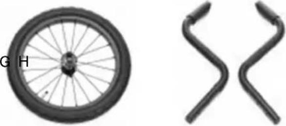
Components
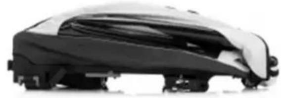
A. 1x frame cover
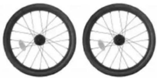
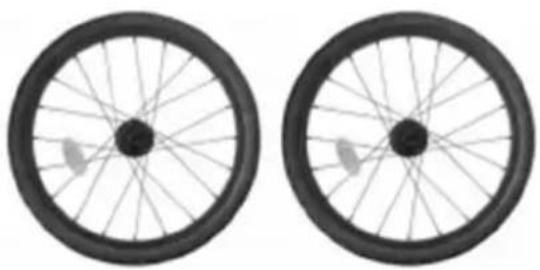
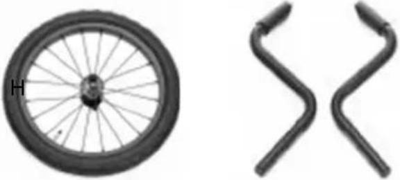
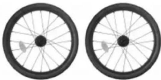
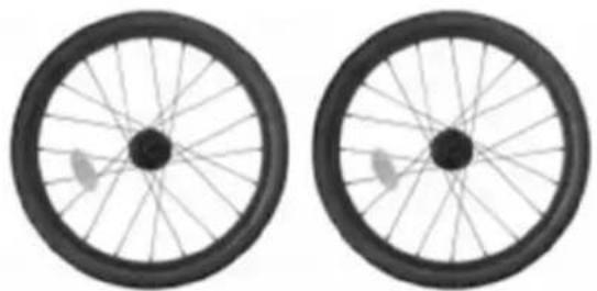
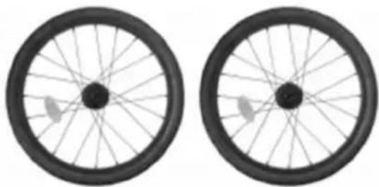
B. 2x rear wheels with reflector
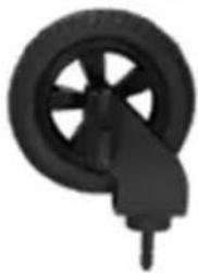
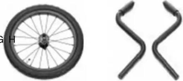
C. 1x jogger wheel (sold separately)
D. 2x wheel outrigger (sold separately)
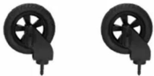
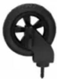
E. 2x buggy wheel
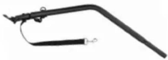
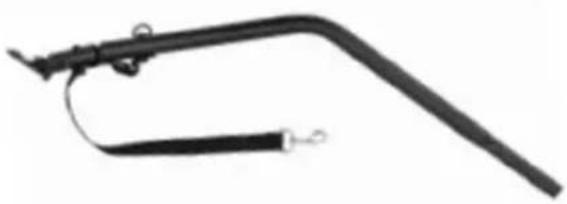
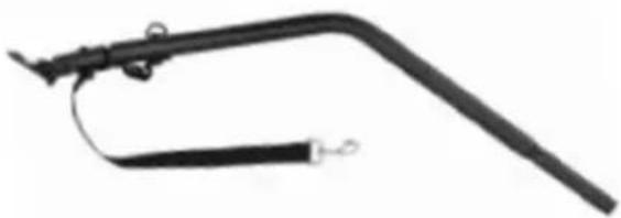
F. 1x drawbar with axle coupling.
G. 1x axle coupling.
H. 1x safety pennant
A
natural_image
Side view of a black and white car covered in protective cover (no visible text or symbols)B
natural_image
Two identical black bicycle wheel rim diagrams with spokes and wheels, shown from top and side views (no text or symbols)F

natural_image
Black mechanical tool with curved handle and attached lever (no visible text or symbols)D
natural_image
Two identical black wheel components with handles, shown from different angles (no text or symbols)C

natural_image
Two bicycle wheel components: one with a labeled 'G' and 'H' on the left, and two curved metal brackets on the right (no text or symbols on the parts themselves)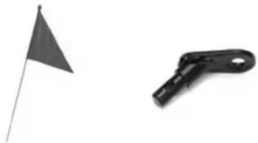
natural_image
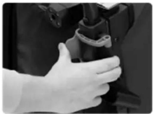
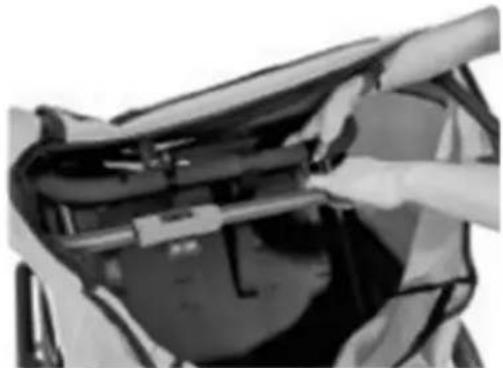
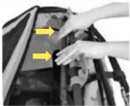
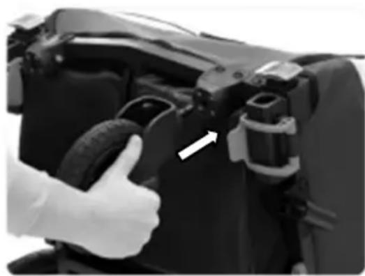
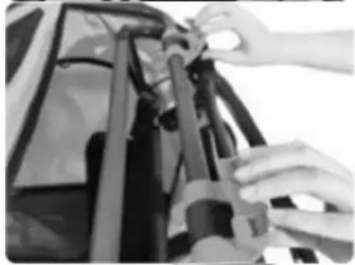
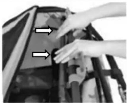
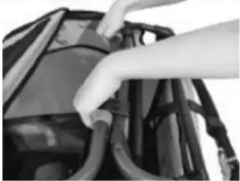
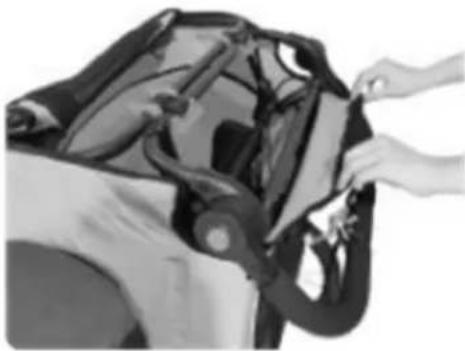
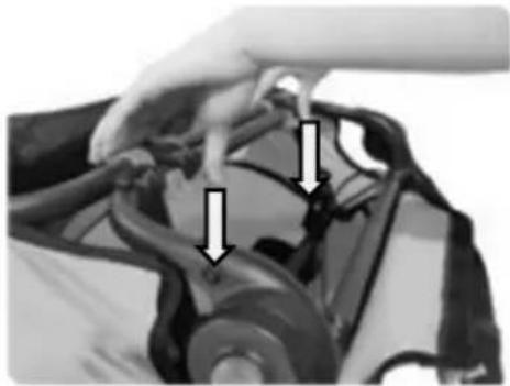
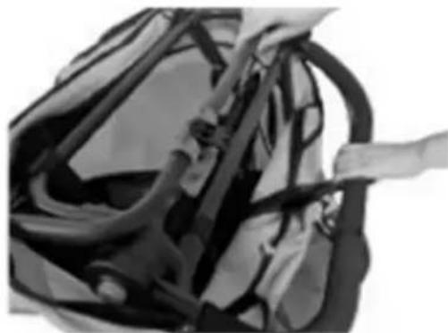
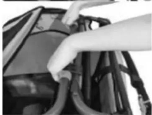
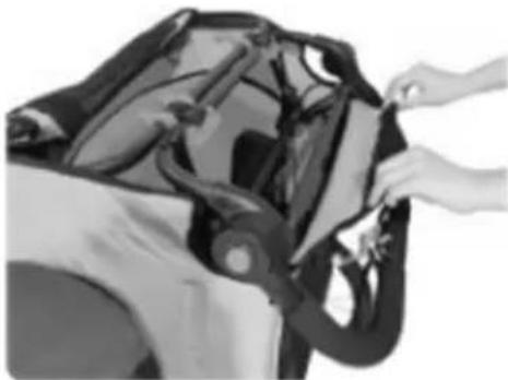
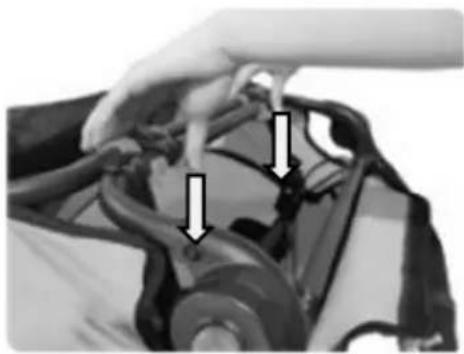
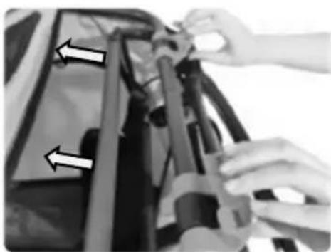
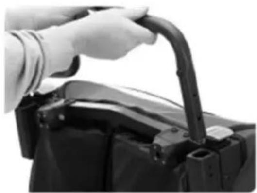
Two small objects: a flag on a pole and a black mechanical clip with a handle (no text or symbols visible)- Reach into the folded bicycle trailer and pull the handlebar.
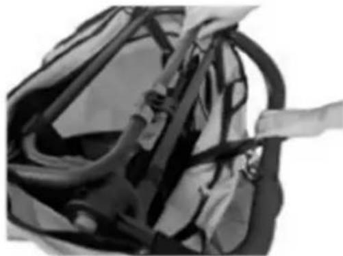
- Pass the frame part to which the handlebar is attached under the linkage of the frame.
Note: The angle of the handlebar can be adjusted by pressing both grey buttons simultaneously.
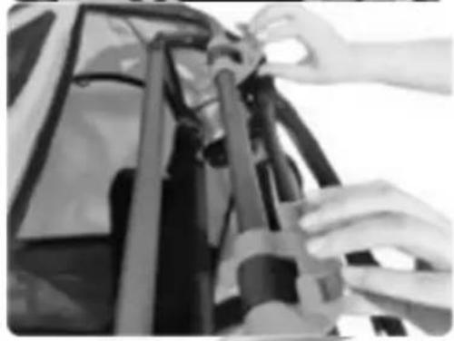
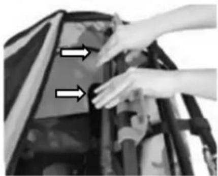
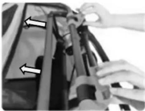
- Connect the frame part to which the handlebar is attached to the frame of the bicycle trailer using the black fastening hooks.
- Secure the black fastening hooks by turning the blue locks until they engage.
- The parts are correctly connected to each other when the connection looks like in picture 5, the textile cover is taut and nothing wobbles.
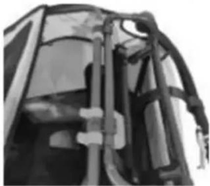
Note: Secure the textile cover by folding it over the frame and closing the Velcro fastener.
1
natural_image
Close-up of a person installing or adjusting a dark object on a vehicle (no visible text or symbols)2
natural_image
Close-up of a bag with straps and straps, no visible text or symbols3
natural_image
Close-up of hands adjusting a mechanical component (no visible text or symbols)3
natural_image
Close-up of hands installing or adjusting a mechanical component with yellow arrows indicating direction (no text or symbols visible)4

natural_image
Close-up of hands installing or adjusting cable harnesses on a vehicle (no visible text or symbols)5

natural_image
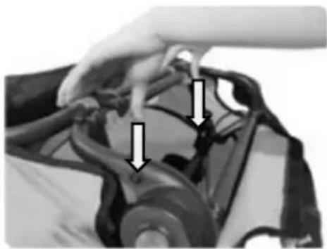
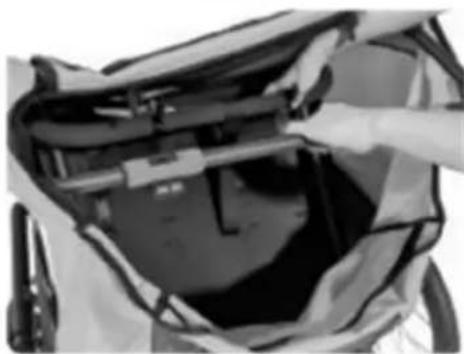
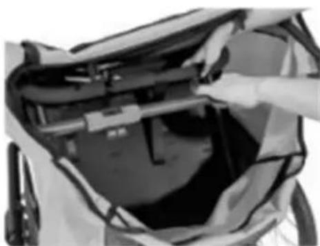
Close-up of a mechanical component with visible brackets and joints (no text or symbols)Folding the base frame
- Set the handlebar to the lowest position.
Note: The angle of the handlebar can be adjusted by pressing both blue buttons simultaneously.
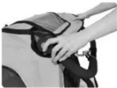
- Open the Velcro fastener that connects the textile cover to the frame.
- To release the blue fastening hooks, press the blue fastening hooks down until they are free.
- Push the frame part to which the handle bar is attached downwards until it is released from the anchorage. Pass this part under the frame linkage.
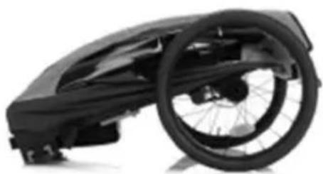
- Now fold the frame together.
- The frame is correctly folded when it looks like in picture.
1
natural_image
Close-up of hands adjusting a car seatbelt (no visible text or symbols)2

natural_image
Person assembling a car body panel with hands adjusting the components (no visible text or symbols)3

natural_image
Close-up of a hand adjusting a car's hood with arrows pointing to the component (no visible text or symbols)4

natural_image
Close-up of hands assembling or adjusting mechanical components with directional arrows (no visible text or symbols)5

natural_image
Close-up of a person's back cover with a hand placing an object on the lid (no visible text or symbols)6

natural_image
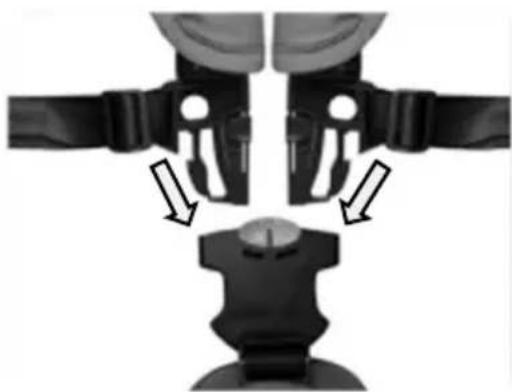
Black and white photo of a wheeled bicycle steering wheel (no text or symbols visible)The 5-point safety harness system consists of two shoulder straps, two lap straps and a crotch strap secured in a buckle. Padded shoulder straps provide more comfort.
WARNING! Never transport babies under 6 months or children who cannot yet sit independently.
- Open the straps by first pressing the red buttons and at the same time the black buttons on the buckle. The individual straps should now come out of the buckle.
- Let the crotch strap hang down towards the footwell and place the two shoulder straps and the lap straps to the sides of the seat for the time being, so that you can comfortably put your child into the seat.
- Place the child in the seat with the harness open.
- Guide the crotch strap with the buckle between the child's legs upwards to the upper body.
- Guide the hands away from the child. And pass the child's hands between the shoulder straps and lap straps. Place the shoulder straps over the child's shoulders.
- Now insert the ends of the straps into the buckle.
Note: The seat belts can be adjusted to the child's height.
- Adjust the seat belts so that the child is held securely by the belts, but not so tight that the seat belts cut in.
Note: If a flat hand can be slid between the straps and the baby's body, the straps are usually adjusted correctly.
WARNING! The distance between the shoulder and lap belts and the child's body should be as small as possible so that the child is held optimally in the seat. If the distance is too great, the child cannot be restrained sufficiently in the seat, which can lead to life-threatening injuries in the event of an accident. If the distance is too small, the seat belts may possibly cut into the child's body.
WARNING! Always fasten the child's seat belt! Your child could otherwise suffer life-threatening injuries in dangerous situations.
WARNING! Seat belts that are adjusted too loosely or buckles that are not properly fastened can cause life-threatening injuries to your child in the event of an accident.
natural_image
Mechanical assembly diagram showing two mechanical components with directional arrows indicating motion or force (no text or symbols present)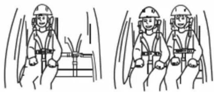
natural_image
Two identical line drawings of workers in safety gear inside a vehicle, showing dynamic motion (no text or symbols)Attaching the rear wheels
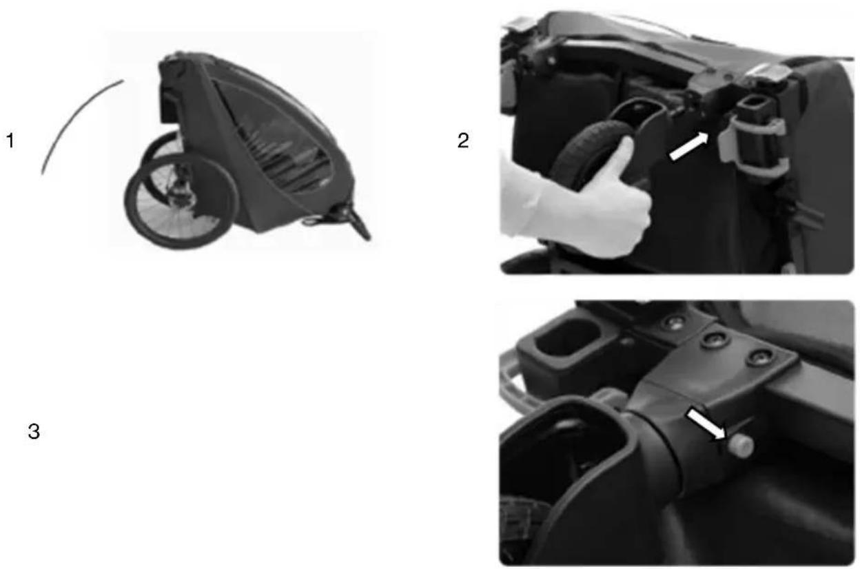
- Insert the rear wheels into the openings on the frame. When you hear a click, the rear wheels are correctly fixed and locked in place.
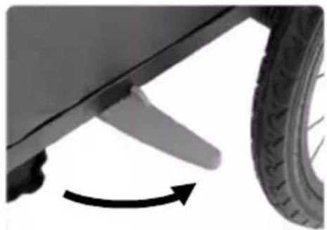
Note: The rear wheels can be removed by pressing the button located in the middle of the wheel. - Extend the wheel guard
Note: Always fold the wheel guard outwards when using it as a bicycle trailer. The wheel guard protects the rear wheels from collision.
1
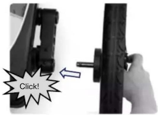
WARNING! After mounting, check the locking by pulling both wheels back and forth! The wheels must not be able to be pulled out without pressing the button. Wheels that are not fully locked can come loose when riding, which can lead to accidents with life-threatening injuries.
WARNING! The right tyres are essential! Use only the tyres supplied and keep them properly maintained. Inflate the tyres to 30-35 P.S. I. and check the pressure before each use. Do not use higher pressure tyres as this will make the trailer bouncy and prone to tipping over when lightly loaded. We recommend only tyres with road tread. Do not use off-road tyres.
2
natural_image
Close-up of a car's wheel and propeller with an arrow indicating rotational motion (no text or symbols)Note: The wheel guard protects the wheels from collisions with obstacles
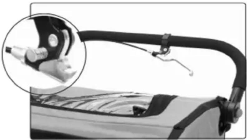
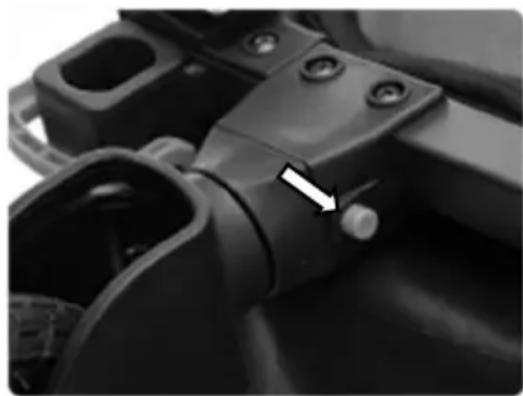
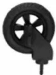
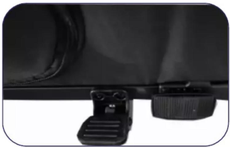
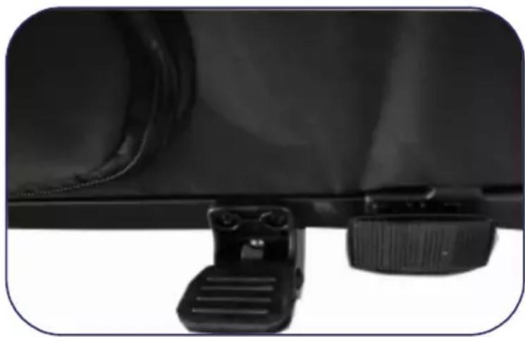
The parking brake prevents the bicycle trailer from unintentionally rolling away when stationary. It is not suitable for breaking a rolling bicycle trailer. Always apply the parking brake when you:
- park the jogger or buggy.
- allow your child to get in and out of the trailer when using it as a jogger, buggy or bicycle trailer.
- fold the trailer so that it does not roll away.
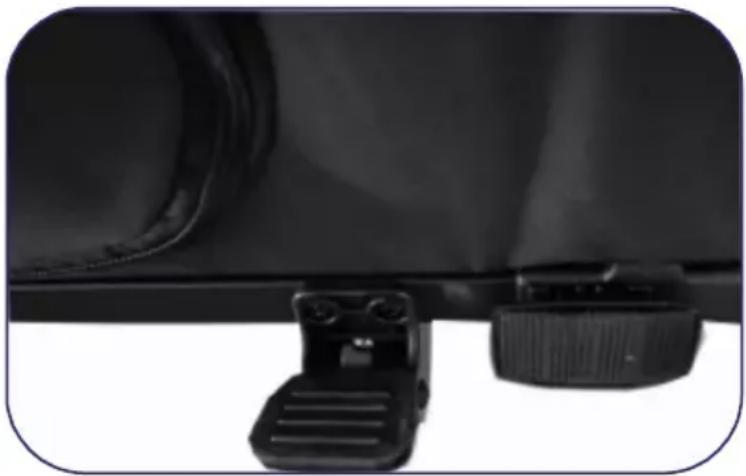
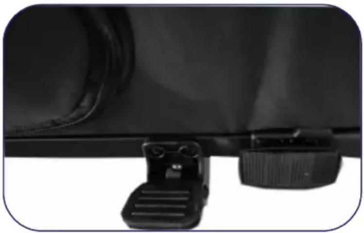
The parking brake is operated by a brake lever located on the handlebar and acts on both wheels release the foot brake. The parking brake can be fixed by pressing the silver button on the brake lever. The parking brake can be released by pulling the brake lever again.
WARNING! Always apply the parking brake after parking the trailer and when getting in and out of the trailer with the children. Check that the trailer cannot roll away by pulling it slightly forwards and backwards. An unsecured trailer could cause accidents with life-threatening injuries by rolling away or could roll away when getting in or out of the trailer, causing serious injuries to the children.
WARNING! Never drive with the parking brake applied! This can damage the brake mechanism.
Hand brake
natural_image
Close-up of a mechanical device with a magnified inset showing internal components (no visible text or symbols)Stopping device
natural_image
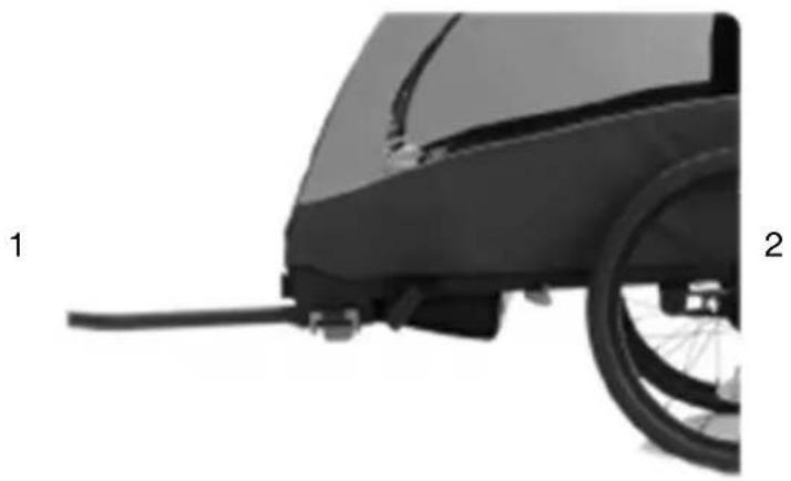
Close-up of a black mechanical component with two adjustment knobs and a handle attachment (no visible text or symbols)Attaching the drawbar (bicycle trailer configuration)
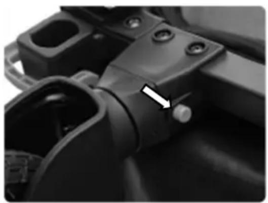
- Insert the drawbar into the opening on the frame. The opening is located under the front reflector.
- Secure the drawbar with the blue clamp. To do this, insert both steel bolts of the clamp into the holes on the side of the bicycle trailer and close the clamp. The clamp is securely closed as soon as you hear a loud click.
Note: Opening and closing the clamp is not smooth and requires a certain amount of force. This is necessary to guarantee a secure hold of the clamp.
- The drawbar must always be mounted on the left side of the bicycle trailer. The drawbar must not be mounted on the right-hand side.
natural_image
Side view of a black bicycle rear bumper with a wheel and attached cable (no text or symbols visible)
natural_image
Close-up of a hand holding a mechanical lock and connecting rod, with an arrow pointing to a component (no visible text or symbols)Caution: The drawbar must always be mounted on the left side of the bicycle trailer.
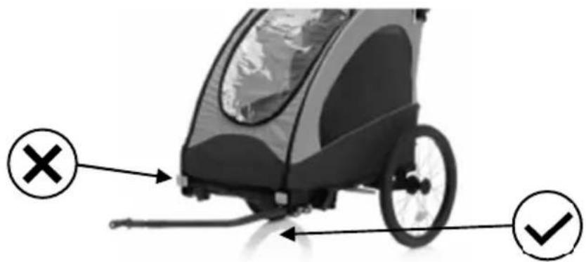
Caution!
Both steel bolts must always be locked with the clamp when the trailer is used. Always make sure that the drawbar is securely mounted. Failure to do so may result in serious accidents and injuries..
The coupling is always mounted on the left-hand side of the tractor wheel, as seen in the direction of travel. It consists of two parts: the drawbar head, which is attached to the drawbar, and the axle coupling, which is attached to the axle of the rear wheel hub of the towing bicycle. Before you mount the axle coupling, you must determine whether your bicycle is suitable for towing a trailer. Check the owner's manual of the bicycle, ask the manufacturer or ask a bicycle dealer.
WARNING! The axle coupling must be fitted correctly. An incorrectly mounted axle coupling can come loose while riding and lead to accidents with life-threatening injuries.
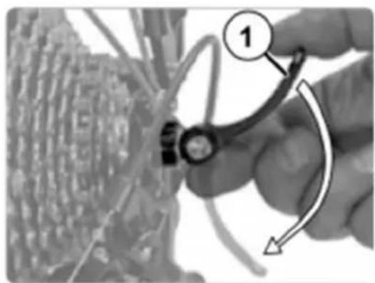
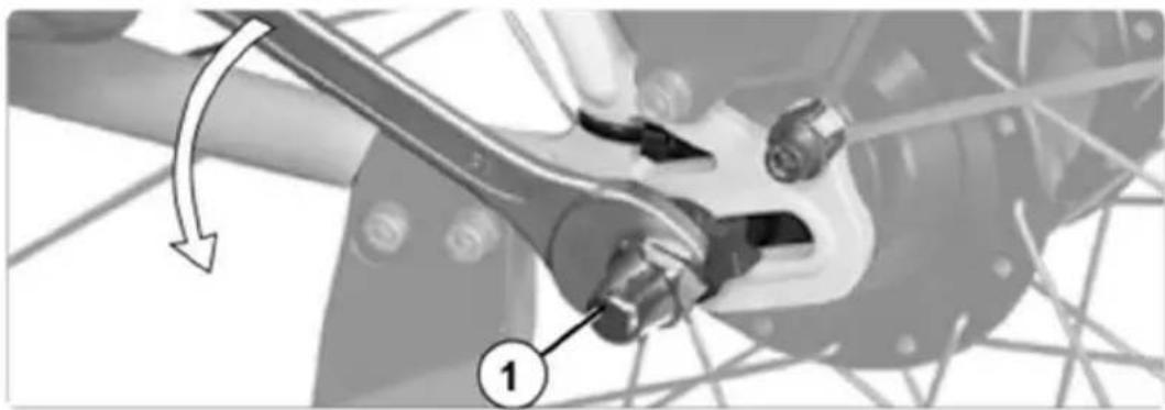
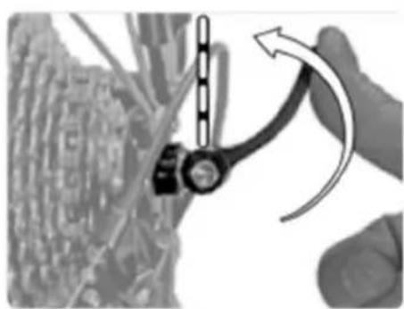
- Open the quick-release lever on the rear wheel of the traction bike or loosen the hexagon socket screw (5 mm), depending on the version of the quick-release axle. Often the direction of movement of the clamping lever is marked "OPEN".
- Unscrew the quick-release axle nut anticlockwise. Be careful, there is a small spring underneath that could jump away.
- Place the axle coupling on the quick-release axle without removing the spring.
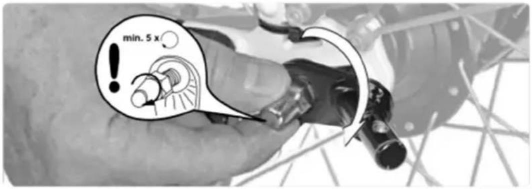
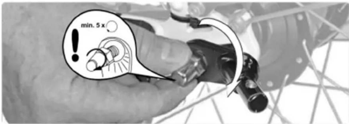
- Screw the axle nut clockwise onto the thread of the quick-release axle with at least five full turns.
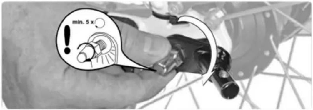
- Align the rear wheel and close the quick-release lever or tighten the hexagon socket screw, depending on the quick-release axle version. The direction of movement of the clamping lever is often marked "CLOSE". The force you apply must increase from about half way. In the last area shortly before the end position, the clamping lever should be difficult to move. In the end position the lever must be parallel to the frame and must not stick out.
- Check whether the quick-release is really tightly closed by trying to turn the closed quick-release around its own axis. If the quick-release can be twisted, the clamping force is not sufficient. Open the clamping lever and screw the axle nut half a turn clockwise. Repeat steps 5 and 6. If the clamping lever cannot be closed completely, open the clamping lever and screw the axle nut half a turn anticlockwise. Repeat steps 5 and 6. Note that the axle nut must be screwed onto the thread of the quick-release axle with at least five full turns.
WARNING! Less than five full turns of the thread will not ensure sufficient clamping force of the rear wheel, which can lead to accidents with life-threatening injuries. The quick-release axle is then too short and must be replaced. This is available as an accessory. Contact a specialist workshop.
- Finally, try to move the rear wheel in the dropouts to make sure that it is correctly fixed.
WARNING! The rear wheel must be correctly fastened after mounting the axle coupling. An incorrectly fastened rear wheel can lead to accidents with life-threatening injuries when riding. Refer to the instruction manual of your towing bicycle. There are many different axles. If in doubt, consult a specialist mechanic.
natural_image
Close-up of a hand holding a mechanical component with a numbered callout (1), no visible text or symbols on the main subject.
natural_image
Close-up of a hand using a tool to adjust or install electronic components on a circuit board (no visible text or symbols)
natural_image
Close-up of a hand adjusting a mechanical component with a magnified inset showing a circular detail (no text or symbols visible)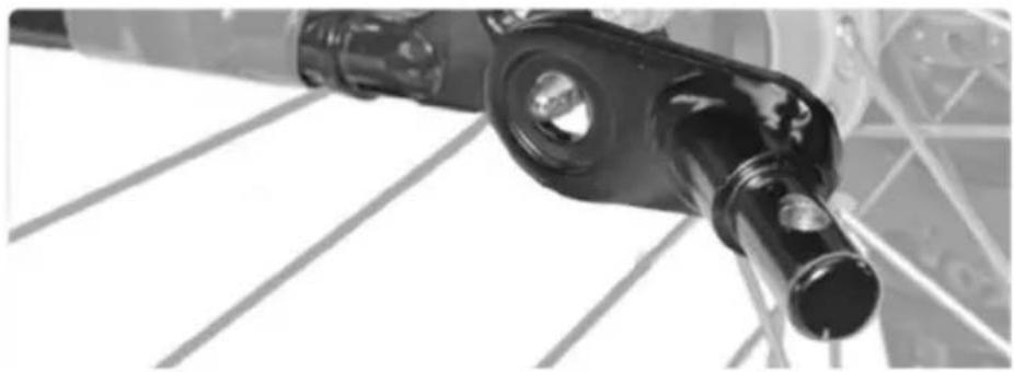
natural_image
Close-up of a mechanical component with cylindrical and rectangular parts, possibly a valve or connector (no visible text or symbols)

natural_image
Diagram showing a mechanical component with an arrow indicating motion or force direction (no text or symbols present)
natural_image
Close-up of a hand using a screwdriver to adjust or install a circuit board component (no visible text or symbols)Assembly of the axle coupling (solid axle)
The coupling is always mounted on the left-hand side of the tractor wheel, as seen in the direction of travel. It consists of two parts: the drawbar head, which is attached to the drawbar, and the axle coupling, which is attached to the axle of the rear wheel hub of the towing bike. Before you mount the axle coupling, you must determine whether your bicycle is suitable for towing a trailer. Check the owner's manual of the bicycle, ask the manufacturer or ask a bicycle dealer.
WARNING! The axle coupling must be fitted correctly. An incorrectly mounted axle coupling can come loose while riding and lead to accidents with life-threatening injuries.
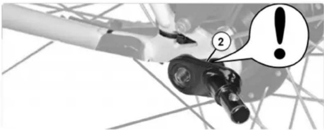
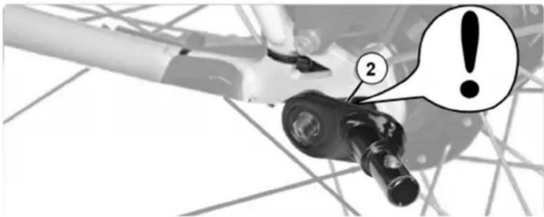
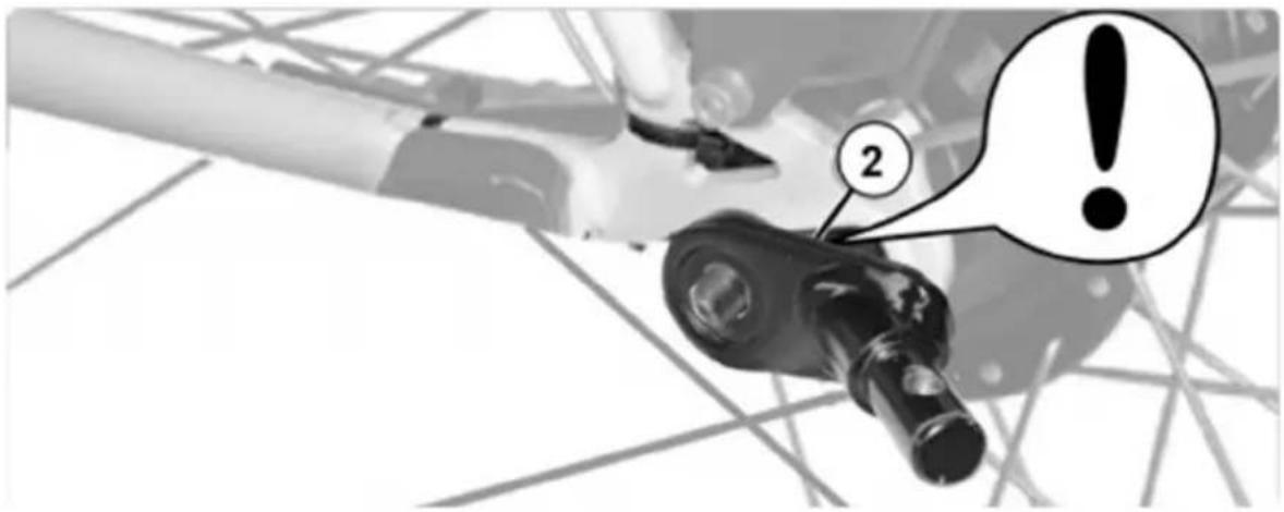
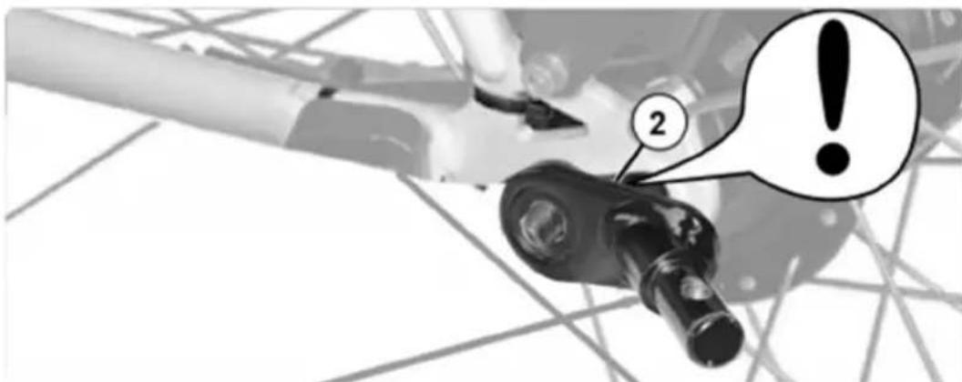
- Unscrew the axle nut on the left side of the rear wheel counterclockwise.
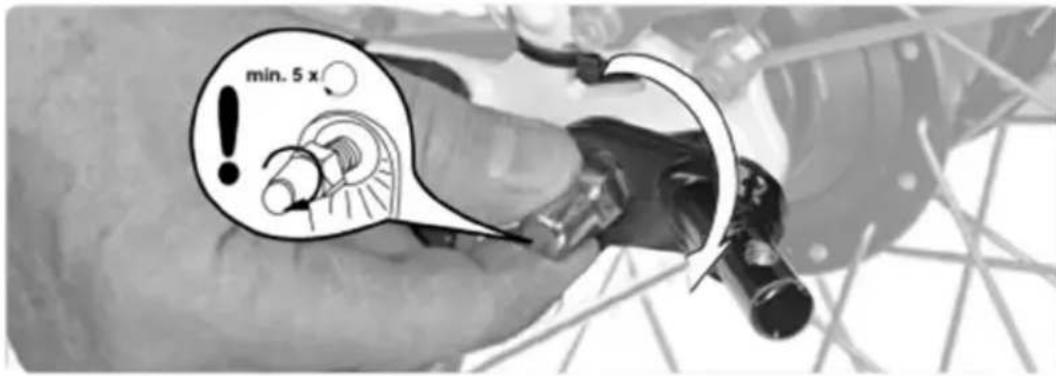
WARNING! Do not remove the lock washer (2). It prevents the rear wheel from twisting in the dropouts. Riding without lock washers can lead to accidents with life-threatening injuries. Place the axle coupling on the axle without removing the lock washer. - Screw the axle nut onto the thread of the solid axle with at least five full turns.
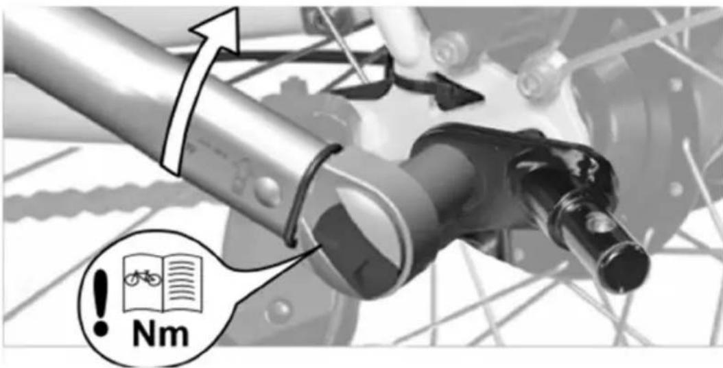
WARNING! Less than five full turns will not ensure sufficient clamping force of the rear wheel, which can lead to accidents with life-threatening injuries. The axle coupling must not be fitted! Contact a specialist workshop. - Align the rear wheel and tighten the axle nut to the tightening torque specified in the instruction manual of your towing bicycle. Hold the axle coupling firmly.
- Finally, try to move the rear wheel in the dropouts to make sure it is correctly secured.
WARNING! The rear wheel must be correctly fixed after mounting the axle coupling. An incorrectly fastened rear wheel can lead to accidents with life-threatening injuries when riding. Observe the operating instructions for your towing bicycle. If in doubt, consult a specialist workshop.
1
natural_image
Mechanical assembly diagram showing a lever mechanism with a numbered component (1) and directional arrow, no readable text or symbols present.2
3
4

Attaching the safety pennant (bicycle trailer configuration)
To ensure that other road users better see the bicycle trailer, you should always use the safety pennant provided. This increases your safety and that of your child. The safety pennant is inserted into a fabric tunnel located on the left side of the fabric cover.
- put the two parts of the frame together.
- put the safety pennant together.
- put the safety pennant into the fabric tunnel on the fabric cover.
WARNING! If you use the bicycle trailer as a bicycle trailer, the safety pennant must always be fitted. Without the safety pennant, the bicycle trailer could easily be overlooked in road traffic, which could lead to accidents with life-threatening injuries.
Note: When folding the trailer, remove the safety pennant beforehand. Otherwise, the pennant pole could break.
natural_image
Simple geometric shape: a black triangle with a horizontal line extending from its right side (no text or symbols)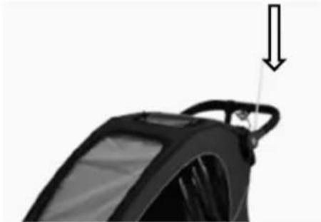
natural_image
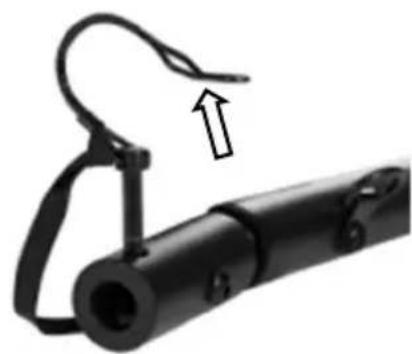
Close-up of a black car wheel handle with a downward arrow indicating force or motion (no text or symbols)Coupling the trailer to the bicycle (bicycle trailer configuration)
WARNING! Check whether the towing bike is approved by the manufacturer for towing trailers! Pulling trailers with an unsuitable towing bike can lead to frame fractures and accidents with life-threatening injuries.
Coupling should always be done without a child in the trailer.
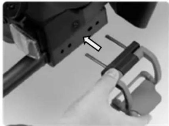
- Open the safety bar of the cotter pin. The cotter pin is located on the drawbar head and remove the cotter pin.
- Lift the drawbar and push the drawbar head onto the axle coupling mounted on the bicycle.
- Put the cotter pin back into the hole provided on the drawbar head and close the safety bar.
Caution! Make sure that the connection is secure by pulling on the drawbar.
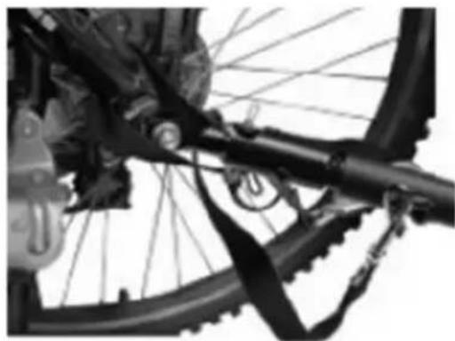
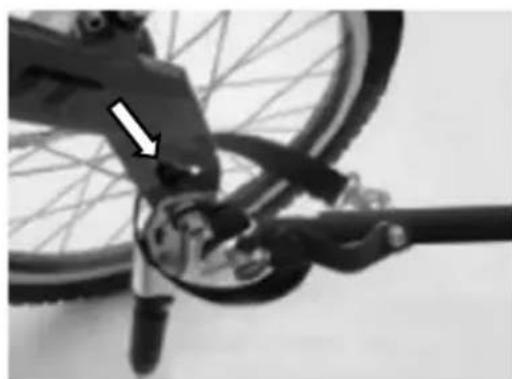
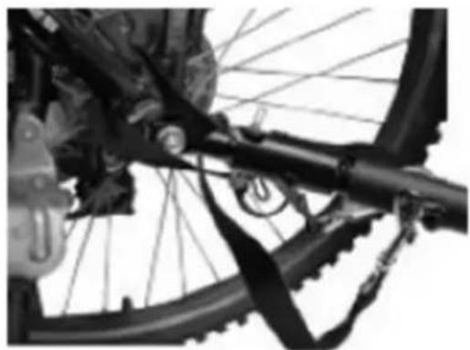
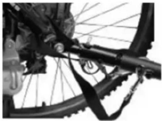
- Pass the safety strap around the frame tube and hook the carabiner into the holder on the drawbar. Make sure that the safety strap does not get caught in the spokes or disc brakes.
WARNING! Make sure that the axle coupling is correctly fixed in the drawbar head. If it is not fixed correctly, the trailer may come loose while driving, which may lead to accidents with life-threatening injuries.
WARNING! Never drive without securing the drawbar with the safety strap! If the trailer comes loose, it will still be connected to the bicycle. Failure to observe this can lead to accidents with life-threatening injuries.
1
natural_image
Close-up of a black mechanical device with a curved handle and an arrow indicating upward motion (no text or symbols)2
natural_image
Close-up of a bicycle wheel and suspension system (no visible text or symbols)4
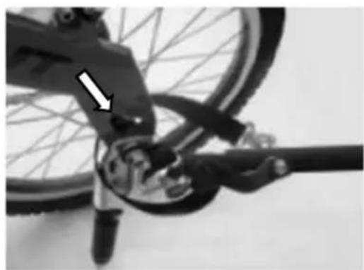
natural_image
Close-up of a bicycle's wheel and suspension mechanism, showing mechanical components and a white arrow indicating a specific part (no text or symbols present)Mounting the buggy wheels (buggy configuration)
If the bicycle trailer has the drawbar or the jogger wheel set mounted, first remove these elements, and insert the blue fastening hooks back into the holes provided. Make sure that the fastening hooks are closed.
Note: To familiarize yourself with the assembly, we recommend that you first lift the bicycle trailer at the front, tilt it backwards and support it on the handlebar. Make sure that the surface under the trailer is clean and smooth so as not to soil or damage the textile cover. Later, when you are familiar with the assembly, it is enough to lift the trailer slightly at the front for this work.
- lift the trailer at the front or tilt it backwards.
- insert the buggy wheel into the buggy wheel holder as far as it will go until you hear and feel it engage.
- to remove the buggy wheel, press the blue button and pull the buggy wheel out.
Caution! Never ride with a mounted buggy wheel when using the trailer as a bicycle trailer! The buggy wheel could hit obstacles, which could lead to accidents and injuries.
Caution! Make sure that the buggy wheel is correctly engaged and cannot come loose by itself! If the buggy wheel is not correctly engaged, the buggy wheel can come loose, which can lead to accidents and injuries.
Mounting the jogger wheel (jogger configuration)
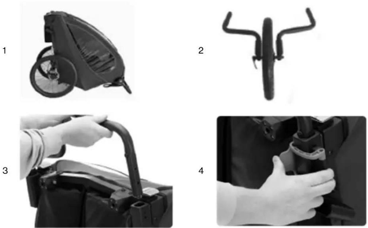
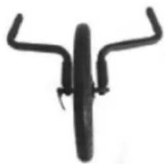
If the drawbar or the buggy wheels are mounted on the bicycle trailer, first dismantle these elements. The jogger set consists of two wheel-arms, a jogger wheel and a catch strap. The two wheel outriggers are mounted in a similar way to the drawbar. The left-hand outrigger is inserted into the receptacle of the drawbar and the right-hand outrigger is inserted into an identically constructed receptacle on the right-hand side.
- Lift the trailer at the front or tilt it backwards.
- Now insert the jogger wheel into the dropouts of the wheel arms and do not tighten the axle nut completely.
- open and remove the blue clips. Then insert the wheel arms into the receptacles. The blue adjustment wheels must point downwards.
- Fix the wheel arms with the help of the blue clamps. To do this, insert both steel bolts of the clamp into the holes on the side of the bicycle trailer and close the clamp. Then tighten the axle nut, close the quick-release lever. Check that the wheel and outriggers are fixed by pulling on them.
Note: Opening and closing the clamp is not smooth and requires a certain amount of force. This is necessary to guarantee a secure hold of the clamp.
WARNING! The jogger wheel and the wheel outriggers must be correctly fixed after assembly. Riding with an incorrectly fastened jogger set can lead to accidents with life-threatening injuries. If in doubt, contact a specialist workshop!
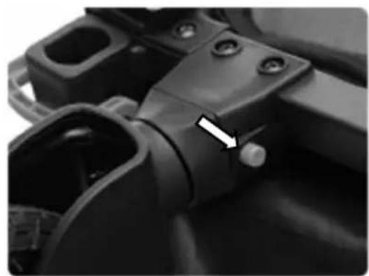
Note: If the trailer does not drive exactly straight ahead in the jogger configuration, the track can be adjusted by turning the adjusting rings on the dropouts.
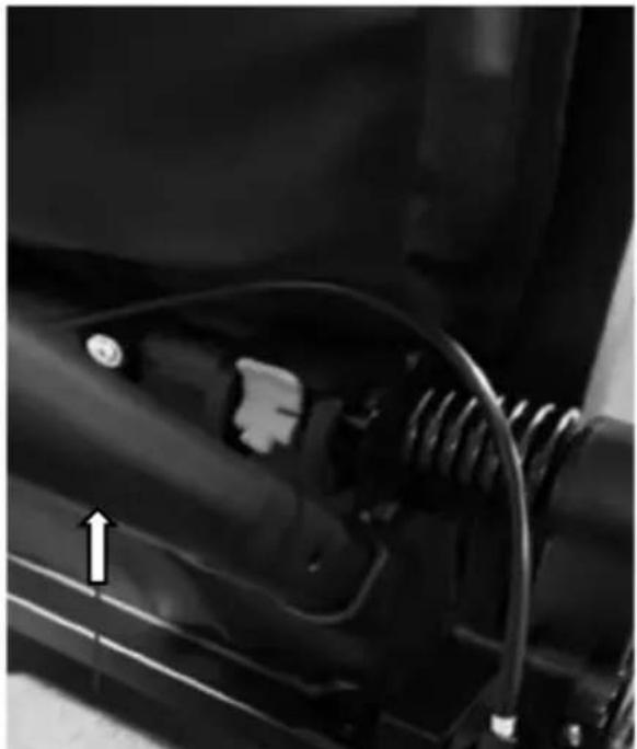
Adjust the positions of wheel suspension.
There are two positions of rear wheel suspension. In the 1st position, it is for the maximum weight in 22kgs; And in the 2nd position, it is for the maximum weight in 22+22kgs.
When you open the frame, the suspension in the 1st position. If you want to take maximum weight more than 22kgs, please use the tow bar, and lift it into the 2nd position. When adjusting from the 2nd position to the 1st position, you need to lift the tow bar first and press the blue button down at the same time. When it falls off, then press the tow bar down.
natural_image
Close-up of a mechanical component with visible wiring and a directional arrow (no text or symbols)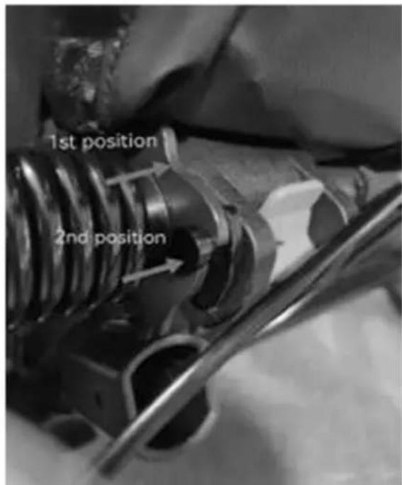
WARNING: Please be sure to adjust the shock gear according to the weight or number of passengers.
Care & Maintenance
- Maintain and clean the trailer regularly to keep it in good condition for a long time.
• Check your trailer and accessories regularly for damage and signs of wear:
- Check all metal components for possible breaks or cracks. Do not use the trailer if any metal components are cracked or damaged.
- Check the trailer for bent, defective, missing or loose fasteners or catches. Tighten loose fasteners or catches and replace damaged or missing parts.
• Inspect the fabric regularly for tears, worn spots or other signs of damage.
- Clean the child carrier regularly with warm water and a mild soap solution. Never use aggressive cleaning agents or solvents.
- Clean the wheel axles and lubricate all exposed moving parts with grease or oil. Always check the wheels and carry out maintenance at least once a year.
- Storage:
- Store your trailer and accessories in a dry place out of direct sunlight. Before storage, the child carrier must be dry to prevent the formation of mould or bacteria.

WICHTIG! SORGFÄLTIG LESEN UND FÜR ZUKÜNFTIGE REFERENZ AUFBEWAHREN.
natural_image
Side view of a black and white industrial machine component (no visible text or symbols)B
natural_image
Two identical black bicycle wheel rim pairs shown from top and side, no text or symbols present.F
natural_image
Black mechanical lever with attached rod and lever handle (no text or symbols visible)D
natural_image
Close-up of a black bicycle steering wheel with a handle (no text or symbols visible)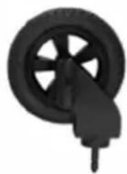
natural_image
Black and white illustration of a wheel with a handle, no text or symbols presentC
natural_image
Two bicycle wheel components: one with a circular head and spokes, the other with two curved brackets (no text or symbols visible)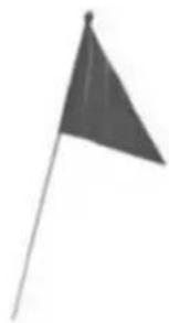
natural_image
Simple grayscale illustration of a flag on a pole (no text or symbols)
natural_image
Close-up of a person installing or adjusting a mechanical component, no visible text or symbols2

natural_image
Close-up of a person's backpack with straps and straps (no visible text or symbols)3

natural_image
Close-up of hands adjusting a mechanical component (no visible text or symbols)3
natural_image
Close-up of hands installing or adjusting a mechanical component with directional arrows (no text or symbols visible)4

natural_image
Close-up of a hand adjusting a car's seatbelt with visible hoses (no text or symbols)5
natural_image
Close-up of a mechanical component with visible structural elements (no text or symbols)natural_image
Mechanical assembly diagram showing two black components with directional arrows indicating movement or force (no text or symbols present)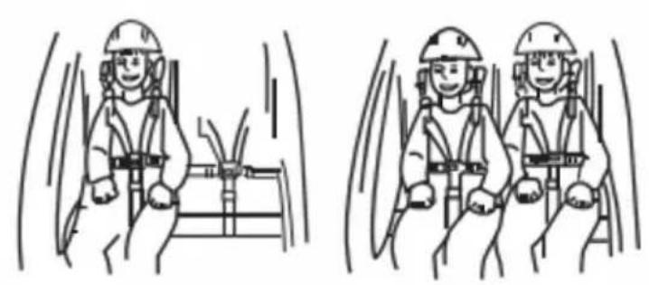
natural_image
Two identical line drawings of a worker in safety gear inside a vehicle, showing head positions and seatbelt (no text or symbols)natural_image
Close-up of a car's wheel and propeller with an arrow indicating rotational motion (no text or symbols)natural_image
Side view of a black and gray bicycle trailer with a wheel and attached cable (no visible text or symbols)2
natural_image
Close-up of a hand holding a key inserted into a mechanical component, with an arrow pointing to a hole (no text or symbols visible)natural_image
Diagram of a baby toy car with directional arrows and checkmark indicators (no text or symbols)Vorsicht!
natural_image
Close-up of a hand holding a mechanical component with a numbered callout (1) and curved arrow indicating motion or direction (no readable text or symbols)
natural_image
Close-up of a hand using a tool to adjust or install a circuit board component (no visible text or symbols)
natural_image
Close-up of a hand adjusting a mechanical component with a magnified inset showing a circular detail (no text or symbols visible)
natural_image
Close-up of a black mechanical component with circular ports and a cylindrical shaft, mounted on a metal frame (no visible text or symbols)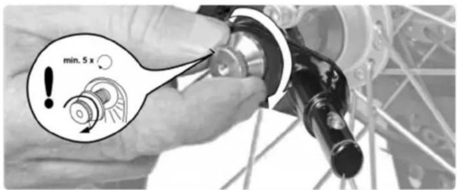

natural_image
Diagram showing a mechanical linkage mechanism with motion arrows, no text or symbols present
natural_image
Close-up of a hand using a screwdriver to adjust a mechanical component (no visible text or symbols)natural_image
Mechanical assembly diagram showing a lever and pin assembly with a numbered component (1), no readable text or symbols present.2

3

4

natural_image
Two grayscale images: one showing a triangular shape and the other showing a device with a handle and a downward arrow (no text or symbols)natural_image
Close-up of a black mechanical device with a curved handle and arrow indicating motion (no text or symbols)2
natural_image
Close-up of a bicycle wheel and suspension system with visible mechanical components (no text or symbols)4

natural_image
Close-up of a bicycle's wheel and suspension mechanism, showing mechanical components and a white arrow indicating a specific point (no text or symbols present)natural_image
Black and white photo of a wheeled cart with wheels, no visible text or symbols2
natural_image
Close-up of a hand giving a thumbs-up gesture to a camera body component (no visible text or symbols)3
natural_image
Close-up of a mechanical component with a white arrow pointing to a small knob (no visible text or symbols)Montage des Joggerrads (Jogger-Konfiguration)
natural_image
Close-up of a mechanical component with springs and wiring, no visible text or symbols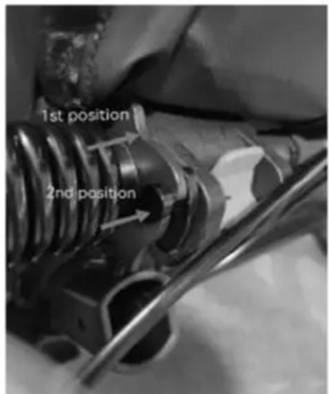
WARNUNG:
natural_image
Side view of a covered outdoor vehicle or machine component (no visible text or symbols)B
natural_image
Two identical black bicycle wheel rim with spokes and wheels, shown from top and side views (no text or symbols)F

natural_image
Black metal tool with curved handle and attached clip, isolated on white background (no text or symbols)D
natural_image
Close-up of a black bicycle wheel with a hand pointing to it (no text or symbols visible)
natural_image
Close-up of a black bicycle wheel with a handle, no visible text or symbolsC
natural_image
Two mechanical components: a circular frame with labeled 'G' and 'H' and two curved metal rods (no text or symbols on the objects themselves)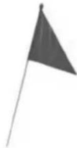
natural_image
Simple grayscale illustration of a flag on a pole (no text or symbols)
natural_image
Person installing or adjusting a device on a vehicle chassis (no visible text or symbols)
natural_image
Close-up of hands adjusting a mechanical component (no visible text or symbols)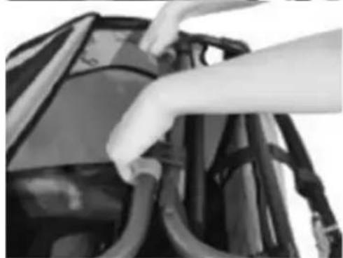
natural_image
Close-up of hands installing or adjusting cable or cable components on a vehicle (no visible text or symbols)
natural_image
Close-up of a bag with visible straps and straps, no text or symbols present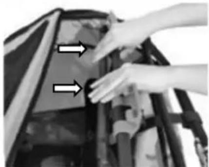
natural_image
Close-up of hands installing or adjusting a mechanical component with two arrows pointing to the part (no text or symbols visible)
natural_image
Close-up of a mechanical component with visible structural elements (no text or symbols)natural_image
Close-up of hands adjusting a car seatbelt (no visible text or symbols)2

natural_image
Person assembling a car body panel with hands adjusting the components (no visible text or symbols)3
natural_image
Close-up of a hand adjusting a car's hood with arrows pointing to the component (no visible text or symbols)4

natural_image
Close-up of hands assembling or adjusting mechanical components with directional arrows (no visible text or symbols)5
natural_image
Close-up of a person's back cover with a hand placing an object on the lid (no visible text or symbols)6
natural_image
Black and white photo of a wheeled bicycle steering wheel (no text or symbols visible)Turvavyön käyttö
natural_image
Mechanical assembly diagram showing two black components with directional arrows indicating movement or force (no text or symbols present)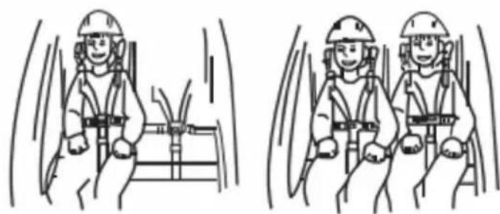
natural_image
Two identical line drawings of a worker in safety gear inside a vehicle cabin, showing head positions and seatbelt (no text or symbols)natural_image
Close-up of a car's wheel and side panel with a curved arrow indicating motion (no text or symbols)natural_image
Close-up of a mechanical device with a magnified inset showing internal components (no visible text or symbols)Pysäytyslaite
natural_image
Close-up of a black mechanical component with two adjustment knobs and a curved surface (no text or symbols visible)natural_image
Side view of a black bicycle trailer with wheels and a cable attachment (no text or symbols visible)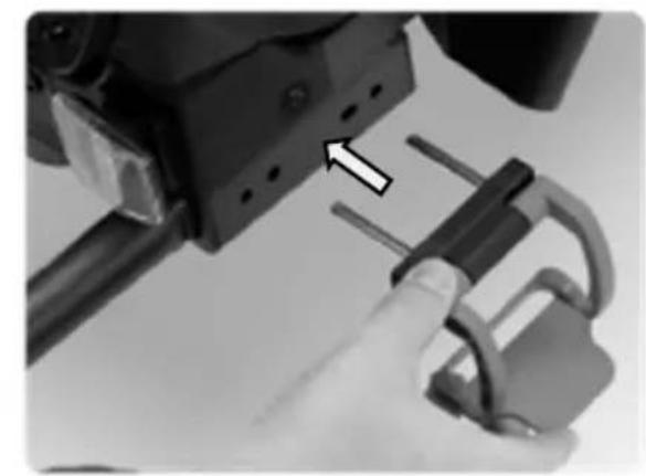
natural_image
Close-up of a hand holding a 3D mechanical component with a lock mechanism, no visible text or symbolsVaroitus!
natural_image
Close-up of a hand holding a mechanical component with a numbered callout (1) and curved arrow indicating motion or direction (no readable text or symbols)
natural_image
Close-up of a hand using a tool to adjust or install a circuit board component (no visible text or symbols)
natural_image
Close-up of a hand adjusting a mechanical component with a magnified inset showing a circular detail (no text or symbols visible)
natural_image
Close-up of a black mechanical component with circular ports and a cylindrical shaft, mounted on a metal frame (no visible text or symbols)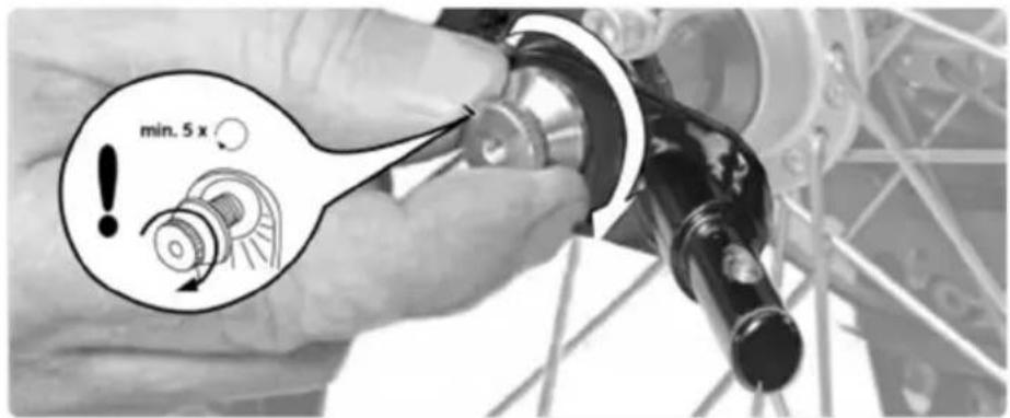

natural_image
Diagram showing a mechanical linkage mechanism with motion arrows, no text or symbols present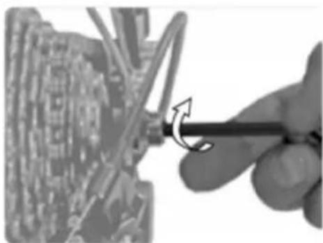
natural_image
Close-up of a hand using a screwdriver to adjust a mechanical component (no visible text or symbols)natural_image
Mechanical assembly diagram showing a lever mechanism with a numbered component (1) and directional arrow, no readable text or symbols present.2
3
4
natural_image
Two grayscale images: one showing a triangular object and the other showing a black mechanical device with a downward arrow (no text or symbols)natural_image
Black and white photo of a wheeled cart with wheels and a curved arrow indicating motion (no text or symbols)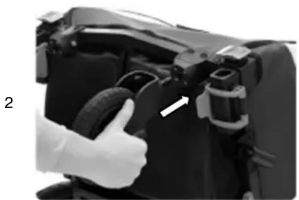
natural_image
Close-up of a hand giving a thumbs-up gesture to a car engine component, no visible text or symbols3
natural_image
Close-up of a mechanical component with a white arrow pointing to a small cylindrical feature (no visible text or symbols)natural_image
Side view of a black and white industrial machine component (no visible text or symbols)B

natural_image
Two identical black bicycle wheel rim diagrams with spokes and wheels, shown from top and side views (no text or symbols)F
natural_image
Black mechanical tool with curved handle and attached wires (no visible text or symbols)D
natural_image
Close-up of a black bicycle steering wheel with a handle (no text or symbols visible)
natural_image
Black and white illustration of a wheel with a handle, no text or symbols presentC

natural_image
Two bicycle wheel components shown side by side: one with a circular head and tire, the other with two curved metal brackets (no text or symbols visible)
natural_image
Simple grayscale illustration of a flag on a pole (no text or symbols)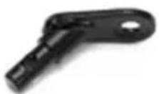
natural_image
Close-up of a person installing or adjusting a mechanical component on a vehicle (no visible text or symbols)2

natural_image
Close-up of a rugged backpack with visible straps and straps (no text or symbols)3
natural_image
Close-up of hands adjusting a mechanical component (no visible text or symbols)3
natural_image
Close-up of hands installing or adjusting a mechanical component with directional arrows (no text or symbols visible)4
natural_image
Close-up of hands connecting a car's seat frame to a vehicle (no visible text or symbols)5

natural_image
Close-up of a mechanical component with visible brackets and joints (no text or symbols)natural_image
Close-up of hands adjusting a car seatbelt (no visible text or symbols)2
natural_image
Person assembling a car body panel with hands adjusting parts (no visible text or symbols)3
natural_image
Close-up of a hand adjusting a car hood with two arrows pointing to the handle (no text or symbols visible)4
natural_image
Close-up of hands assembling or adjusting mechanical components with directional arrows (no visible text or symbols)5

natural_image
Close-up of a person's torso and back panel with a hand placing a component (no visible text or symbols)6

natural_image
Close-up of a black wheeled bicycle steering wheel (no text or symbols visible)natural_image
Mechanical assembly diagram showing two black clamps with directional arrows indicating movement or force (no text or symbols)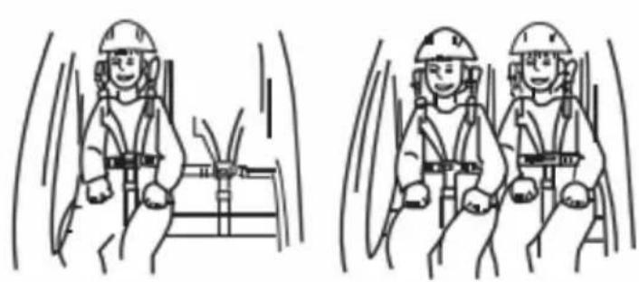
natural_image
Two identical line drawings of a person wearing safety helmets inside a vehicle cabin, with motion lines indicating speed (no text or symbols)natural_image
Close-up of a car wheel and propeller with an arrow indicating motion (no text or symbols)natural_image
Side view of a black bicycle rear bumper with a wheel and attached cable (no text or symbols visible)
natural_image
Close-up of a hand holding a mechanical lock and connecting rod, with an arrow pointing to the lock component (no text or symbols visible)Prudence!
natural_image
Close-up of a hand holding a mechanical component with a numbered callout (1) and curved arrow indicating motion or direction (no readable text or symbols)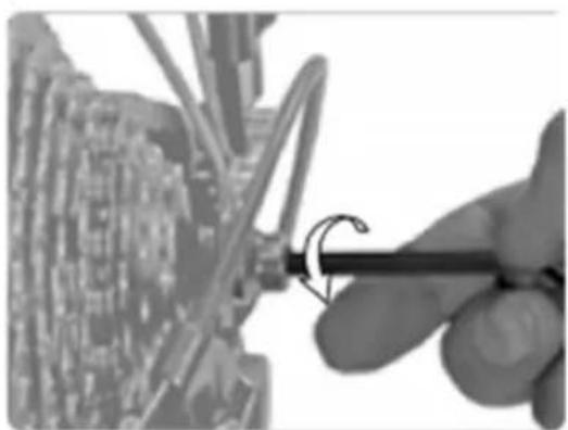
natural_image
Close-up of a hand using a tool to adjust or install a circuit board component (no visible text or symbols)
natural_image
Close-up of a hand adjusting a mechanical component with a magnified inset showing a circular detail (no text or symbols visible)
natural_image
Close-up of a black mechanical component with circular ports and a cylindrical shaft, mounted on a metal frame (no visible text or symbols)

natural_image
Diagram showing a mechanical linkage mechanism with motion arrows, no text or symbols present
natural_image
Close-up of a hand using a screwdriver to adjust a mechanical component (no visible text or symbols)natural_image
Mechanical assembly diagram showing a lever mechanism with a numbered component (1) and directional arrow, no readable text or symbols present.FR
2
3
4

natural_image
Simple geometric shape: a dark triangular prism with a thin line extending from its right side (no text or symbols)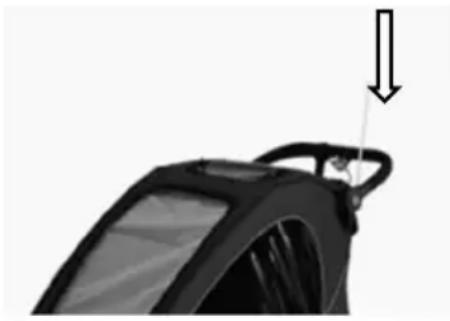
natural_image
Close-up of a black mechanical component with a downward arrow indicating force or motion (no text or symbols visible)natural_image
Close-up of a black cylindrical device with a curved handle and an arrow pointing to it, no visible text or symbols.2

natural_image
Close-up of a bicycle wheel and suspension system with visible mechanical components (no text or symbols)4

natural_image
Close-up of a bicycle's front wheel and suspension mechanism, showing mechanical components and a white arrow pointing to the component (no text or symbols visible)natural_image
Black and white photo of a wheeled cart with wheels and a curved arrow indicating motion (no text or symbols)
natural_image
Close-up of a hand giving a thumbs-up gesture to a car tire component (no visible text or symbols)3

natural_image
Close-up of a mechanical component with a white arrow pointing to a small component (no visible text or symbols)Montage de la roue de jogging (configuration jogger)
AVERTISSEMENT:
natural_image
Side view of a black and white industrial machine component (no visible text or symbols)B
natural_image
Two identical black bicycle wheel rim diagrams with spokes and wheels, shown from top and side views (no text or symbols)F
natural_image
Black mechanical tool with curved arm and attached lever (no visible text or symbols)D

natural_image
Close-up of a black bicycle steering wheel with a handle, no visible text or symbols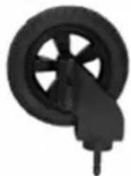
natural_image
Close-up of a black bicycle wheel with a handle, no visible text or symbolsC
natural_image
Two bicycle wheel components shown side by side: one with a circular head and labeled 'G H', the other with two curved metal brackets (no text or symbols on the objects themselves)
natural_image
Simple grayscale flag on a pole, no text or symbols present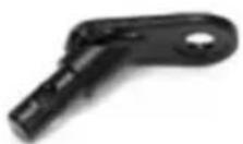
natural_image
Close-up of a person installing or adjusting a mechanical component, no visible text or symbols2
natural_image
Close-up of a black-and-white photo of a person's torso and arm, showing no visible text or symbols.3

natural_image
Close-up of hands adjusting mechanical components on a vehicle (no visible text or symbols)3

natural_image
Close-up of hands installing or adjusting a mechanical component with arrows indicating direction (no text or symbols visible)4
natural_image
Close-up of a hand adjusting a car's front panel with visible wiring (no text or symbols)5

natural_image
Close-up of a mechanical component with visible brackets and joints (no text or symbols)natural_image
Person adjusting a car seatbelt, no visible text or symbols2
natural_image
Person adjusting a car hood with hands adjusting the seat (no visible text or symbols)3
natural_image
Close-up of a hand adjusting automotive components with arrows pointing to specific parts (no visible text or symbols)4

natural_image
Close-up of hands assembling or adjusting mechanical components with directional arrows (no visible text or symbols)5
natural_image
Close-up of a person opening a bicycle seat cover (no visible text or symbols)6
natural_image
Black and white photo of a wheeled bicycle steering wheel (no text or symbols visible)5-punkts sikkerhetsselesystem består av to skulderstropper, to hoftestropper og en skrittrem festet i en spenne. Polstrede skulderstropper gir mer komfort.
natural_image
Mechanical assembly diagram showing two arms with directional arrows indicating movement or force (no text or symbols present)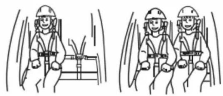
natural_image
Two identical line drawings of workers in safety gear inside a vehicle, showing motion blur (no text or symbols)Feste bakhjulene
natural_image
Close-up of a car's wheel and propeller with an arrow indicating rotational motion (no text or symbols)natural_image
Close-up of a mechanical device with a magnified inset showing internal components (no visible text or symbols)Stoppe enheten
natural_image
Close-up of a black mechanical component with two clamps and a handle, no visible text or symbolsnatural_image
Side view of a black bicycle rear bumper with a wheel and attached cable (no text or symbols visible)
natural_image
Close-up of a hand holding a mechanical lock and connecting rod, with an arrow pointing to a component (no text or symbols visible)Forsiktighet!
natural_image
Close-up of a hand holding a mechanical component with a numbered callout (1) and curved arrow indicating motion or direction (no readable text or symbols)
natural_image
Close-up of a hand using a tool to adjust or install a circuit board component (no visible text or symbols)
natural_image
Close-up of a hand adjusting a mechanical component with a magnified inset showing a circular detail (no text or symbols visible)
natural_image
Close-up of a black mechanical component with circular ports and a cylindrical shaft, mounted on a metal frame (no visible text or symbols)

natural_image
Diagram showing a mechanical linkage mechanism with motion arrows, no text or symbols present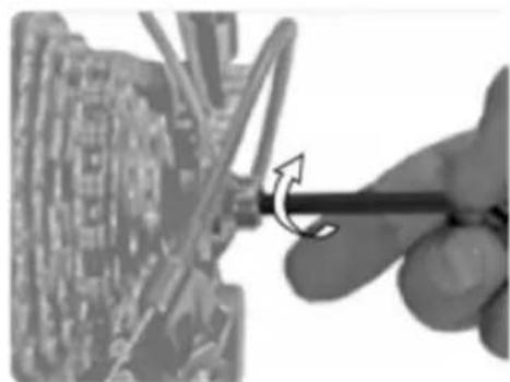
natural_image
Close-up of a hand using a screwdriver to adjust or install a circuit board component (no visible text or symbols)natural_image
Mechanical assembly diagram showing a lever mechanism with a numbered component (1) and directional arrow, no readable text or symbols present.2
3

4

natural_image
Simple geometric shape: a black triangular prism with a horizontal line extending from its base (no text or symbols)
natural_image
Close-up of a black car steering wheel with a handle and arrow indicating force or motion (no text or symbols)natural_image
Close-up of a black cylindrical device with a curved cable and an arrow indicating upward motion (no text or symbols)2
natural_image
Close-up of a bicycle wheel and suspension system, showing mechanical components and wiring (no text or symbols visible)4
natural_image
Close-up of a bicycle's wheel and suspension mechanism, showing mechanical components and a white arrow indicating a specific part (no text or symbols present)ADVARSEL:
natural_image
Side view of a black and white industrial machine component (no visible text or symbols)B
natural_image
Two identical black bicycle wheel rim with spokes and a small triangular component on the left (no text or symbols)F

natural_image
Black metal tool with curved handle and attached strap (no visible text or symbols)D

natural_image
Close-up of a black bicycle wheel with a hand pointing to it (no text or symbols visible)
natural_image
Close-up of a black bicycle wheel with a handle, no visible text or symbolsC

natural_image
Two mechanical components: a circular frame with labeled points and two curved metal rods (no text or symbols present)
natural_image
Simple grayscale illustration of a flag on a pole (no text or symbols)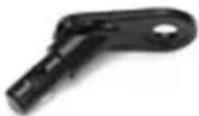
natural_image
Close-up of a person installing or adjusting a mechanical component on a vehicle (no visible text or symbols)
natural_image
Close-up of hands adjusting a mechanical component (no visible text or symbols)
natural_image
Close-up of a bag with visible straps and straps, no text or symbols present
natural_image
Close-up of hands installing or adjusting cable on a vehicle (no visible text or symbols)
natural_image
Close-up of hands installing or adjusting a mechanical component with two arrows pointing to the part (no text or symbols visible)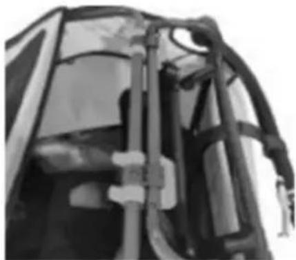
natural_image
Close-up of a mechanical component with visible structural elements (no text or symbols)natural_image
Person adjusting a car seatbelt, no visible text or symbols2

natural_image
Person adjusting a car hood with hands adjusting the seat (no visible text or symbols)3

natural_image
Close-up of a hand adjusting automotive components with arrows pointing to specific parts (no visible text or symbols)4
natural_image
Close-up of hands assembling or adjusting mechanical components with directional arrows (no visible text or symbols)5

natural_image
Close-up of a person opening a bicycle seat cover (no visible text or symbols)6
natural_image
Close-up of a black bicycle steering wheel and chassis (no text or symbols visible)natural_image
Mechanical assembly diagram showing two clamps with directional arrows indicating movement or force (no text or symbols present)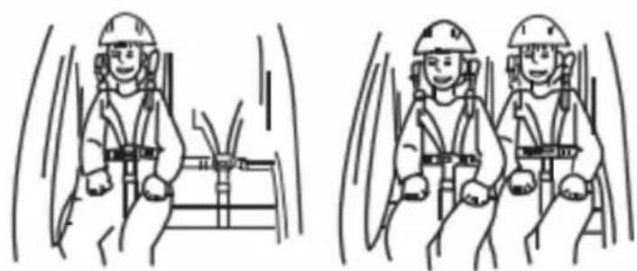
natural_image
Two identical line drawings of workers in safety gear inside a vehicle cabin, showing motion blur (no text or symbols)Fästa bakhjulen
natural_image
Close-up of a car's wheel and propeller with an arrow indicating rotational motion (no text or symbols)natural_image
Close-up of a mechanical device with a magnified inset showing a hand holding a tool, no visible text or symbols.Stoppanordning
natural_image
Close-up of a black mechanical component with two clamps and a cable, no visible text or symbolsnatural_image
Side view of a black bicycle shuttle pod with wheels and a cable attachment (no text or symbols visible)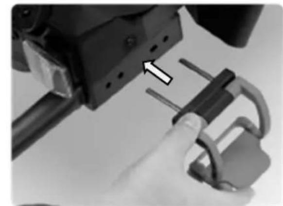
natural_image
Close-up of a hand using a tool to adjust a mechanical component with a lock (no visible text or symbols)Försiktighet!
natural_image
Close-up of a hand holding a mechanical component with a numbered callout (1) and curved arrow indicating motion or direction (no readable text or symbols)
natural_image
Close-up of a hand using a tool to adjust or install a circuit board component (no visible text or symbols)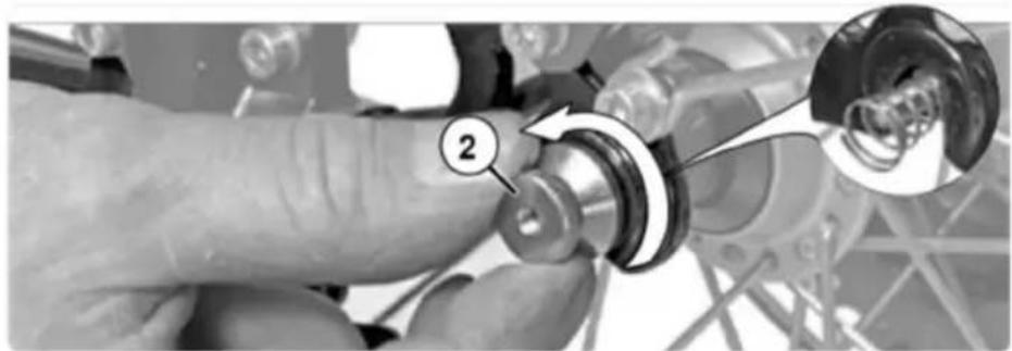
natural_image
Close-up of a hand adjusting a mechanical component with a magnified inset showing a circular detail (no text or symbols visible)
natural_image
Close-up of a black mechanical component with circular ports and a cylindrical shaft, mounted on a metal frame (no visible text or symbols)
natural_image
Diagram showing a mechanical linkage mechanism with motion arrows, no text or symbols present
natural_image
Close-up of a hand using a screwdriver to adjust a mechanical component (no visible text or symbols)natural_image
Mechanical assembly diagram showing a lever mechanism with a numbered component (1) and directional arrow, no readable text or symbols present.2

3
4

natural_image
Simple geometric shape resembling a right triangle with a horizontal line extending from its base (no text or symbols)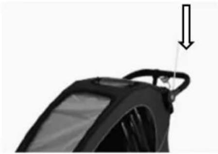
natural_image
Close-up of a black car steering wheel with a handle and arrow indicating force or motion (no text or symbols)natural_image
Black and white photo of a small wheeled cart with a curved arrow indicating motion (no text or symbols)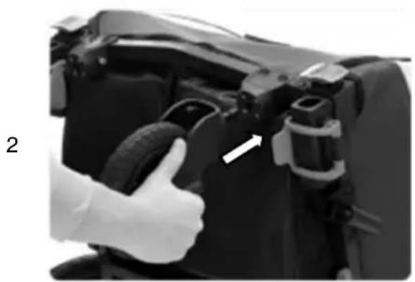
natural_image
Close-up of a hand giving a thumbs-up gesture to a camera body component (no visible text or symbols)3
natural_image
Close-up of a mechanical component with a white arrow pointing to a small feature (no visible text or symbols)Montering av joggarhjulet (joggarkonfiguration)
natural_image
Black and white photo of a small wheeled cart with a circular wheel, no visible text or symbols.2
natural_image
Simple black bicycle head with curved bracing (no text or symbols)3
natural_image
Close-up of a hand holding a flexible hose attached to a black vehicle handle (no visible text or symbols)4