
CPH 401 G DWK X - Cooker Fulgor Milano - Free user manual and instructions
Find the device manual for free CPH 401 G DWK X Fulgor Milano in PDF.
| Brand | Fulgor Milano |
| Model | CPH 401 G DWK X |
| Product Type | Built-in Gas Hob |
| Number of Burners | 1 Dual Wok Burner (double flame) |
| Compatible Gas Type | Natural gas (G20/G25) or LPG (butane/propane) – adaptable |
| Dual Wok Burner Power | Up to 4.5 kW (estimated) |
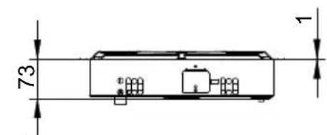
| Overall Dimensions (WxDxH) | 510 x 380 x 73 mm |
| Cutout Dimensions (WxD) | 490 x 360 mm |
| Table Material | Stainless steel (ceramic glass for some parts) |
| Ignition | Automatic spark ignition (electric) |
| Safety | Thermoelectric (automatic gas cut-off in case of extinguishment) |
| Flame Adjustment | Progressive from maximum to minimum |
| Adaptation to Another Gas Type | Possible by changing injectors and adjusting minimum (see manual) |
| Electrical Connection | 230 V - 50/60 Hz - requires grounded outlet |
| Gas Connection | Rigid or flexible metal connection (stainless steel) |
| Installation Class | Class 3 (built into a worktop) |
| Routine Maintenance | Clean burners and caps with water and mild detergent; do not use steam cleaner |
| Usage Precautions | Use pans of suitable diameter; do not leave empty pans on the fire |
| Warranty and Support | Contact Fulgor Milano after-sales service |
Frequently Asked Questions - CPH 401 G DWK X Fulgor Milano
User questions about CPH 401 G DWK X Fulgor Milano
0 question about this device. Answer the ones you know or ask your own.
Ask a new question about this device
Download the instructions for your Cooker in PDF format for free! Find your manual CPH 401 G DWK X - Fulgor Milano and take your electronic device back in hand. On this page are published all the documents necessary for the use of your device. CPH 401 G DWK X by Fulgor Milano.
USER MANUAL CPH 401 G DWK X Fulgor Milano
natural_image
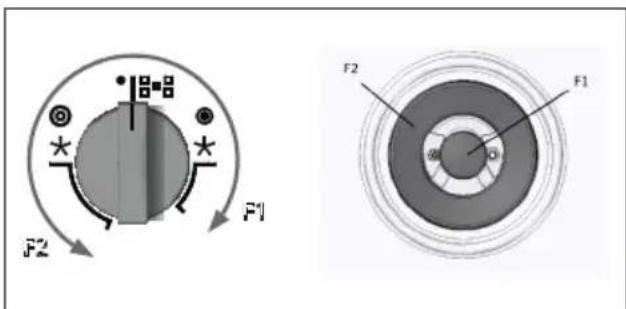
Pure technical line drawings of a mechanical component with cross-sectional views (no text or symbols)dual ∅ 20-32
rapido ∅ 20-24
ausiliario ∅ 10-14
Fig.1
Importante
natural_image
Simple geometric diagram showing a circle inscribed in a square frame (no text or symbols)Allacciamento metallico rigido/semirigido
Fig. 4
natural_image
Line drawing of a hand using a tool to press or install a small object on a flat surface (no text or symbols)Fig. 5

natural_image
3D mechanical component diagram showing a washer and housing assembly (no text or symbols)
natural_image
3D rendering of a mechanical lever assembly with a black head and gray base (no text or symbols visible)
natural_image
Technical line drawing of a mechanical component with a screwdriver inserted (no text or symbols)
natural_image
Pure technical diagram of a mechanical assembly without any text, numbers, or symbols
natural_image
Mechanical lever mechanism diagram showing pivot point and pivot shaft (no text or labels)Fig. 6
| CARATTERISTICHE UTILIZZATORI | ||||
| BRUCIATORI GAS | ||||
| ALIMENTAZIONE TIPO PRESSIONE mbar NORM. | BRUCIATORE | ∅ INIETTORE 1/100 | PORTATA TERMICA NOMINALE | CONSUMO |
| Gas naturale G20 20 | rapido 129 3000 286ausiliario 77 1000 95dual 71A-95B 4000 381 | l/h | ||
| Gas liquido G30/G31 28-30/37 | rapido 87 3000 218ausiliario 50 1000 73dual 46A-65B 4000 291 | g/h | ||
| Gas naturale G25 25 | rapido 132 3000 332ausiliario 80 1000 111dual 71A-100B 4000 443 | l/h | ||
| G20 10 | rapido 155 3000 286ausiliario 92 1000 95dual 80A-143B 4000 381 | l/h | ||

SERVIZIO ASSISTENZA TECNICA: 199.151.195
Dear customer,
We thank you and congratulate you on your choice.
This new carefully designed product, manufactured with the highest quality materials, has been carefully tested to satisfy all your cooking demands.
We would therefore request you to read and follow these easy instructions which will allow you to obtain excellent results right from the start.
May we wish you all the very best with your modern appliance!
THE MANUFACTURER
Index
Instructions for use
Installation
Use
Maintenance
Instructions for the installater
Installation
Gas connection
Electrical connection
User characteristics
THIS APPLIANCE IS CONCEIVED FOR DOMESTIC USE ONLY.
THE MANUFACTURER SHALL NOT IN ANY WAY BE HELD RESPONSIBLE FOR WHATEVER INJURIES OR DAMAGES ARE CAUSED BY INCORRECT INSTALLATION OR BY UNSUITABLE, WRONG OR ABSURD USE. THIS APPLIANCE IS NOT INTENDED FOR USE BY PERSONS (INCLUDING CHILDREN) WITH REDUCED PHYSICAL, SENSORY OR MENTAL CAPABILITIES, OR LACK OF EXPERIENCE AND KNOWLEDGE, UNLESS

Italiano

English

Français

Deutsch

Español

Português
THEY HAVE BEEN GIVEN SUPERVISION OR INSTRUCTION CONCERNING USE OF THE APPLIANCE BY A PERSON RESPONSIBLE FOR THEIR SAFETY.
CHILDREN SHOULD BE SUPERVISED TO ENSURE THAT THEY DO NOT PLAY WITH THE APPLIANCE.
Instructions for use
Installation
All the operations concerned with the installation (electrical and gas connections, adaptation to type of gas, necessary adjustments, etc.) must be carried out by qualified technicians, in terms with the standards in force. For specific instructions, kindly read the part reserved for the installation technician.
Use
Gas burners
The ignition of the gas burner is carried out by putting a small flame to the upper part holes of the burner, pressing and rotating the corresponding knob in an anti-clockwise manner, until the maximum position has coincided with the marker. When the gas burner has been turned on, adjust the flame according to need. The minimum position is found at the end of the anticlockwise rotation direction. In models with automatic ignition, operate the knob as described above, pressing simultaneously, the corresponding push-button. For models with automatic/ simultaneous (with one hand) ignition, it is sufficient to proceed as described above using the corresponding knob. The electric spark between the ignition plug and the burner provides the ignition of the burner itself. After ignition, immediately release the push-button and adjust the flame according to need. For models with a thermoelectric safety system, the burner is ignited as in the various cases described above, keeping the knob fully pressed on the maximum position for approximately 3/5 seconds. After releasing the knob, make sure the burner is actually lit.
Models with Dual Wok burner
Some models have a Dual Wok burner. The centre flame (F1) can be lit by pressing the knob and turning it clockwise or the entire burner (F2) can be lit as shown in the figure below.
N.B
- We recommend the use of pots and pans with a diameter matching that of the burner, thus preventing the flame from escaping from the bottom part and surrounding the pot (Fig. 1);
- do not leave any empty pots or pans on the fire; When cooking is finished, it is also a good norm to close the main gas pipe tap and/or cylinder.
Important
- Use of the appliance produces heat and moisture in the room where it is installed. Make sure the kitchen is sufficiently ventilated; keep natural ventilation holes open or install mechanical ventilation devices (such as a hood).
- Prolonged use of the appliance may require additional ventilation, such as opening a window.
- On floors with thermoelectric protection do not keep the ignite button pushed for more than 15 seconds. If the burner has not ignited after 15 seconds, open the door of the room and wait at least one minute before making a further attempt.
- On floors without protection, should the burner flame go out close the corresponding gas cock and wait at least one minute before making any attempt to ignite it.
Maintenance
Prior to any operation, disconnect the appliance from the electrical system. For long-life to the equipment, a general cleaning operation must take place periodically, bearing in mind the following:
- the glass and steel parts must be cleaned with suitable non-abrasive or corrosive products (found on the market). Avoid chlorine-base products (bleach, etc.);
- avoid leaving acid or alkaline substances on the working area (vinegar, salt, lemonjuice, etc.);
- the wall baffle and the small covers (mobile parts of the burner) must be washed frequently with boiling water and detergent, taking care to remove every possible encrustation. Dry carefully and check that none of the burner holes is fully or partially clogged;
Note:
If the taps need to be lubricated, it must be performed by a qualified technician, who should be contacted in the case of any operating problems.
heck periodically the state of conservation of the flexible gas feed pipe. In case of leakage, call immediately the qualified technicians for its replacement.
DO NOT USE STEAM CLEANERS
Instructions for the installer
Installation
This appliance is not provided with a combustion product discharge. It is recommended that it be installed insufficiently aerated places, in terms of the laws in force. The quantity of air which is necessary for combustion must not be below 2.0 m³/h for each kW of installed power. See table of burner power.
Note:
The appliance is in installation class 3.
The appliance's adjustment parameters are shown on the plate attached to its housing.
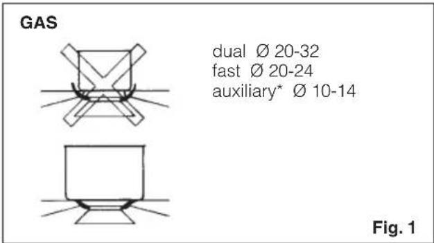
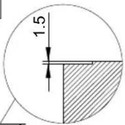
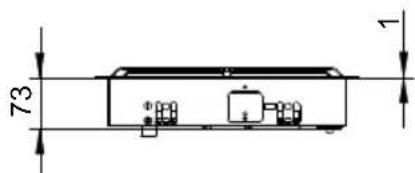
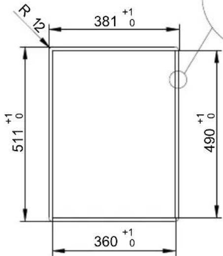
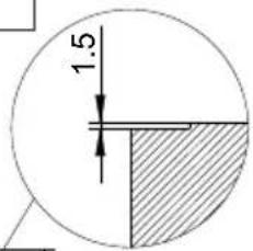
Positioning (Fig. 2)
The cook top is designed to be built in to a work surface as shown in the figure.
Before installing the cook top, install the gasket seal around the entire perimeter of the hole where it will be inserted.
The dimensions of the hole are shown in figures 6-7-8-9. For Filotop models, the perimeter of the hole must be lowered by a depth of 1.5 mm.
The hole does not need to be milled for Semifilotop models.
The cook top can be installed on different materials such as brickwork, steel, marble, conglomerates, synthetics, wood and wood covered with plastic laminates, so long as resistant to a temperature of 90 °C.
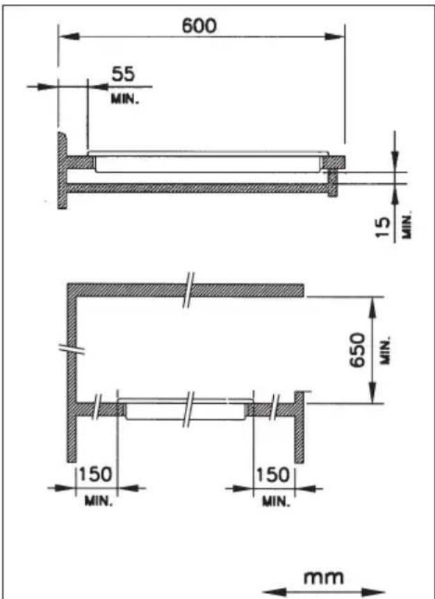
A panel made of wood or other insulating material must be installed under the cook top at a distance of at least 15 mm from the surface.
Fig. 2
Mod: CPH 402 G
Note: Semifilotop models do not need to be lowered by 1.5 mm.
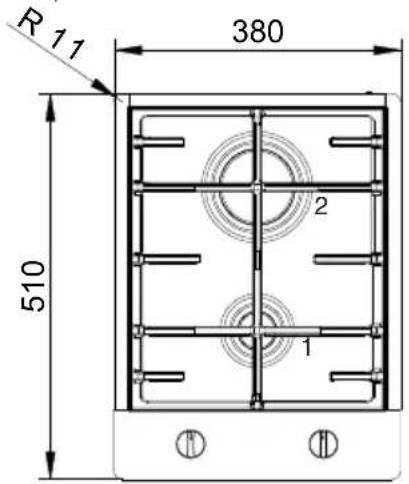
1 - AUXILIARY
2 - RAPID
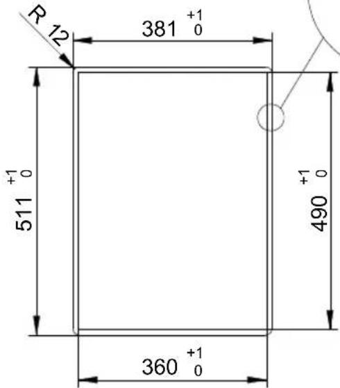
1 - AUXILIARY 2 - RAPID 360 0
Mod: CPH 401 GDWK
Note: Semifilotop models do not need to be lowered by 1.5 mm.
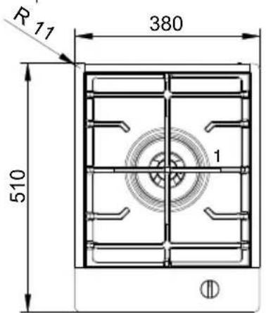
1 - DUAL
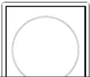
Gas connection (Fig. 3)
The connection to a gas tank or gas line must be made by a qualified person in conformity to current updated UNI-CIG 7129 and 7131 standards after making sure that the cook top is prepared for the type of gas available. If not, see: "Adapting to different types of gas". Also check that the feed pressure falls within the values shown in the table: "User characteristics".
Fig. 3
natural_image
Simple geometric diagram showing a circle inscribed in a square frame (no text or symbols)Metal rigid/semi-rigid hook-ups
Make the hook-up with metal fittings and pipes (even flexible hoses) so as not to stress the components inside the cook top.
Note: - After installation, use soapy water to check the perfect seal of the entire connection system.
Important note: make the connection using only metal fittings and pipes (flexible, continuous-wall steel hoses or rigid copper or steel tubing) and in such a way that its entire length can be inspected.
Electrical connection (Fig. 4)
The installer must be qualified and is responsible for correct electrical connections and following safety standards.
Prior to carrying out the electrical connection, please ensure that:
- the plant characteristics are such as to follow what is indicated on the matrix plate placed at the bottom of the working area;
- that the plant is fitted with an efficient earth connection, following the standards and law provisions in force. The earth connection is compulsory in terms of the law.
Should there be no cable and/or plug on the equipment, use suitable absorption material for the working temperature as well, as indicated on the matrix plate. Under no circumstance must the cable reach a temperature above 50^ C of the ambient temperature.
If connecting directly to the mains power supply, fit a multi-pole switch of a suitable size for the rated capacity
with a clearance distance which completely disconnects the power line under overvoltage category III conditions, consistently with the rules of installation (the yellow/green earth wir must not be interrupted). The plug or omnipolar switch must be easily reached on the installed equipment.
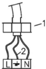
Fig. 4
If the power cord is damaged, it must be replaced by the manufacturer, its service department or a person with similar qualifications, so as to prevent any risk.
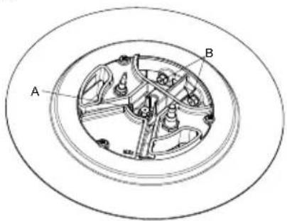
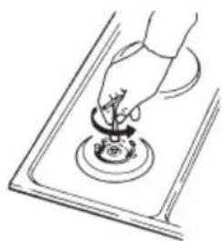
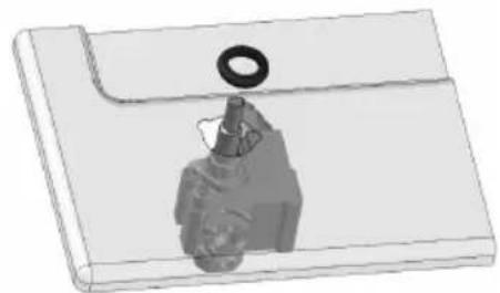
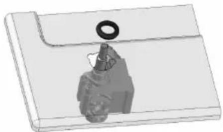
Adaptation to varius types of gas (Fig. 5)
Should the appliance be pre-set for a different type of gas than available, procreed as follows:
- replace the injector (Fig. 5) with the corresponding type of gas to be used (see table "User characteristics");
- to adjust to the minimum, use a screwdriver on the screw placed on the tap (Fig. 6) after turning the tap to its minimum position. For LPG (butane/propane) screw tight.
Mod. Dual
Mod. 2G
natural_image
Line drawing of a hand using a tool to press or install a small object on a flat surface (no text or symbols)Fig. 5
natural_image
3D mechanical component diagram showing a washer and housing assembly (no text or symbols)
natural_image
3D rendering of a mechanical lever assembly with a black head and black shaft (no text or symbols visible)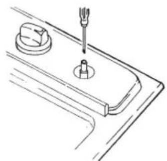
natural_image
Technical line drawing of a mechanical component with a screwdriver inserted (no text or symbols)
natural_image
Simple line drawing of a mechanical component with a washer and housing (no text or symbols)
natural_image
Mechanical lever mechanism diagram showing pivot point and pivot shaft (no text or labels)Fig. 6
| USER CHARACTERISTICS | ||||
| GAS BURNERS | ||||
| FEEDTYPE PRESSURE mbarNORM. | BURNER | ∅ INJECTORS1/100 | THERMALCAPACITY | CONSUMPTION |
| Natural gas G20 20 | fast 129 3000 286auxiliary 77 1000 95dual 71A-95B 4000 381 | I/h | ||
| Liquefied gas G30/G31 28-30/37 | fast 87 3000 218auxiliary 50 1000 73dual 46A-65B 4000 291 | g/h | ||
| Natural gas G25 25 | fast 132 3000 332auxiliary 80 1000 111dual 71A-100B 4000 443 | I/h | ||
| G20 10 | fast 155 3000 286auxiliary 92 1000 95dual 80A-143B 4000 381 | I/h | ||
Chère cliente,
natural_image
Pure geometric line drawing of a symmetrical mechanical or architectural component (no text or symbols)dual ∅ 20-32
rapide ∅ 20-24
auxiliaire* ∅ 10-14
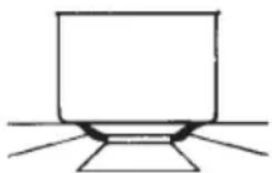
Fig. 1
Important
natural_image
Simple geometric diagram showing a circle inscribed in a square frame (no text or symbols)Fig. 4
natural_image
Line drawing of a hand using a tool to press or install a component on a tray (no text or symbols)Fig. 5

natural_image
3D mechanical component diagram showing a washer and housing assembly (no text or symbols)
natural_image
3D rendering of a mechanical lever assembly with a black handle and two black weights (no text or symbols visible)
natural_image
Technical line drawing of a mechanical component with a screwdriver inserted (no text or symbols)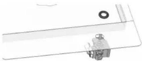
natural_image
Pure technical line drawing of a mechanical component without any text, numbers, or symbols
natural_image
Mechanical lever mechanism diagram showing pivot point and pivot shaft (no text or labels)Fig. 6

| CARACTERISTIQUES UTILISATEURS | ||||
| BRULEURES A GAZ | ||||
| ALIMETATIONTYPE GASTOEVER mbarNORM. | BRULEUR | ∅ INJECTEURS1/100 | DEBIT THERMIQUE NOMINALW | CONSOMMATION |
| Gaz naturel G20 20 | rapide 129 3000 286auxiliaires 77 1000 95dual 71A-95B 4000 381 | 1h | ||
| Gaz liquéfié G30/G31 28-30/37 | rapide 87 3000 218auxiliaires 50 1000 73dual 46A-65B 4000 291 | |||
| Gaz naturel G25 25 | rapide 132 3000 332auxiliaires 80 1000 111dual 71A-100B 4000 443 | 1h | ||
| G20 10 | rapide 155 3000 286auxiliaires 92 1000 95dual 80A-143B 4000 381 | 1h | ||
natural_image
Simple line drawing of a computer monitor with no text or symbolsdual ∅ 20-32
schnell ∅ 20-24
hilfbrenner* ∅ 10-14
Abb. 1
Wichting
natural_image
Simple geometric diagram showing a circle inside a square with label Abb. 3 (no text or symbols within the shapes)natural_image
Line drawing of a hand using a tool to press or install a component on a tray (no text or symbols)Abb. 5

natural_image
3D mechanical component diagram showing a washer and housing assembly (no text or symbols)
natural_image
3D rendering of a mechanical lever assembly with a black handle and two black weights (no text or symbols visible)
natural_image
Technical line drawing of a mechanical component with a screwdriver inserted (no text or symbols)
natural_image
Simple line drawing of a mechanical component with a washer and housing (no text or symbols)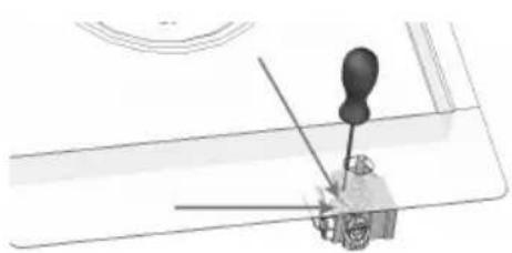
natural_image
Mechanical lever mechanism diagram showing pivot point and pivot shaft (no text or labels)Abb. 6

| TECHNISCHE DATEN | ||||
| GASBRENNSTELLEN | ||||
| SPEISUNG TYP DRUCK mbar NORMAL | BRENNERTYP | ∅ DÜSENELEMENTE 1/100 | WÄRMEBELASTUNG NOMINAL W | VERBRAUCH |
| Naturgas G20 20 | schnell 129 3000 286hilfsbrenner 77 1000 95dual 71A-95B 4000 381 | 1h | ||
| Naturgas G30/G31 28-30/37 | schnell 87 3000 218hilfsbrenner 50 1000 73dual 46A-65B 4000 291 | |||
| Naturgas G25 25 | schnell 132 3000 332hilfsbrenner 80 1000 111dual 71A-100B 4000 443 | 1h | ||
| G20 10 | schnell 155 3000 286hilfsbrenner 92 1000 95dual 80A-143B 4000 381 | 1h | ||
Estimado Cliente,
natural_image
Pure technical line drawings of a mechanical component with cross-sectional views (no text or symbols)dual ∅ 20-32
rápido ∅ 20-24
auxiliar ∅ 10-14
Fig. 1
Importante
natural_image
Simple geometric diagram showing a circle inside a square, labeled 'Fig. 3' (no text or symbols within the diagram itself)natural_image
Line drawing of a hand using a tool to press or install a component on a flat surface (no text or symbols)Fig. 5
natural_image
3D mechanical component diagram showing a washer and housing assembly (no text or symbols)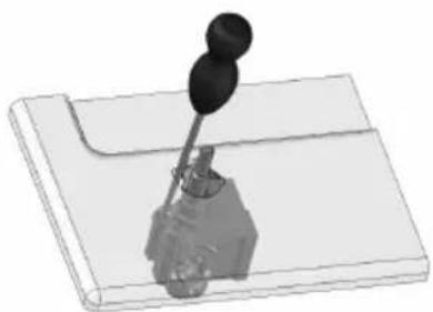
natural_image
3D rendering of a mechanical lever assembly with a black handle and two black weights (no text or symbols visible)
natural_image
Technical line drawing of a mechanical component with a screw and base (no text or symbols)
natural_image
Pure technical diagram of a mechanical component without any text, numbers, or symbols
natural_image
Mechanical lever mechanism diagram showing pivot point and pivot shaft (no text or labels)Fig. 6
| CARACTERISTICAS UTILIZADORES | ||||
| QUEMADORES DE GAS | ||||
| ALIMENTACION TIPO PRESION mbar NORM. | QUEMADOR | ∅ INYECTORES 1/100 | CAPACIDAD TÉRMICA | CONSUMPTION |
| Gas natural G20 20 | rápido 129 3000 286auxiliar 77 1000 95dual 71A-95B 4000 381 | 1h | ||
| Gas licuefacto G30/G31 28-30/37 | rápido 87 3000 218auxiliar 50 1000 73dual 46A-65B 4000 291 | |||
| Gas natural G25 25 | rápido 132 3000 332auxiliar 80 1000 111dual 71A-100B 4000 443 | 1h | ||
| G20 10 | rápido 155 3000 286auxiliar 92 1000 95dual 80A-143B 4000 381 | 1h | ||
Ex.mo. Sr. Cliente,
natural_image
Simple geometric diagram showing a circle inside a square, labeled 'Fig. 3' (no text or symbols within the diagram itself)natural_image
Line drawing of a hand using a tool to press or install a component on a tray (no text or symbols)Fig. 5

natural_image
3D mechanical component diagram showing a washer and housing assembly (no text or symbols)
natural_image
3D rendering of a mechanical lever assembly with a black head and black shaft (no text or symbols visible)
natural_image
Technical line drawing of a mechanical component with a screwdriver inserted (no text or symbols)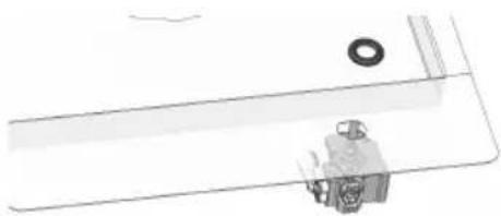
natural_image
Pure technical diagram of a mechanical assembly without any text, numbers, or symbols
natural_image
Mechanical lever mechanism diagram showing pivot point and pivot shaft (no text or labels)Fig. 6
| CARACTERÍSTICAS DAS PEÇAS A UTILIZAR | ||||
| QUEIMADORES DE GAS | ||||
| ALIMENTAÇÃO TIPO PRESSÃO mbar NORM. | QUEIMADOR | ∅ BICOS 1/100 | CAPACIDADE TÉRMICA | CONSUMO |
| Gás natural G20 20 | ràpido 129 3000 286auxiliar 77 1000 95dual 71A-95B 4000 381 | 1h | ||
| Gás licuefeito G30/G31 28-30/37 | ràpido 87 3000 218auxiliar 50 1000 73dual 46A-65B 4000 291 | |||
| Gás natural G25 25 | ràpido 132 3000 332auxiliar 80 1000 111dual 71A-100B 4000 443 | 1h | ||
| G20 10 | ràpido 155 3000 286auxiliar 92 1000 95dual 80A-143B 4000 381 | 1h | ||