
FHH 800 ID TC BK - Cooker Fulgor Milano - Free user manual and instructions
Find the device manual for free FHH 800 ID TC BK Fulgor Milano in PDF.
| Product Type | Induction hob with integrated hood |
| Brand | Fulgor Milano |
| Model | FHH 800 ID TC BK |
| Dimensions (W x D x H) | 800 x 520 x 255 mm |
| Net weight | 20.0 kg |
| Power supply | 220-240 V single phase or 380-415 V three phase, 50/60 Hz |
| Max total power | 7.4 kW |
| Number of zones | 4 induction zones |
| Power levels | 9 levels + Booster (P) |
| Special functions | Booster, Bridge, Chef Cook, Auto Heat-Up, Warming, Pause, Recall, Key Lock, Child Lock |
| Timer | Independent timer (up to 600 min) and per-zone timer (up to 119 min) |
| Hood type | Extraction mode (to outside) or recirculation mode (recycling with charcoal filter) |
| Fan speeds | 9 speeds + Booster (P) |
| Filters | Metal grease filters (washable) and ceramic charcoal filter (regenerable in oven at 200°C) |
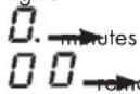
| Filter maintenance indicator | Grease filter every 30 h, odor filter every 120 h |
| Automatic functions | Automatic hood operation, Fan after-run, pan detection |
| Safety | Safety shutdown, pan detection, residual heat indicator (H), child lock, touch lock, motor overheat protection |
| Surface material | Glass ceramic |
| Cleaning and maintenance | Clean with a damp cloth and dish soap, avoid abrasive products, clean filters and condensation tray regularly |
| Installation | Built into worktop, requires adequate ventilation, safety distance 500 mm above |
| Included accessories | Adhesive seal, centering springs, air connection screw, user manual |
| Warranty | 2 years (parts and labor) |
Frequently Asked Questions - FHH 800 ID TC BK Fulgor Milano
User questions about FHH 800 ID TC BK Fulgor Milano
0 question about this device. Answer the ones you know or ask your own.
Ask a new question about this device
Download the instructions for your Cooker in PDF format for free! Find your manual FHH 800 ID TC BK - Fulgor Milano and take your electronic device back in hand. On this page are published all the documents necessary for the use of your device. FHH 800 ID TC BK by Fulgor Milano.
USER MANUAL FHH 800 ID TC BK Fulgor Milano
natural_image
Four black circles arranged in a 2x2 grid on white background (no text or symbols)FHH 600 ID TC BK
FHH 800 ID TC BK
INDUCTION COOKING HOB
TABLE DE CUISSON INDUCTION
INDUKTIONSKOCHFELD
natural_image
Illustration of an electrical circuit breaker with a hand giving a thumbs-up gesture (no text or symbols present)Fig. 2
natural_image
Illustration of kitchen utensils including fork, knife, screwdriver, and plate (no text or symbols)natural_image
Technical line drawing of a mechanical assembly inside a 3D enclosure, showing internal components and directional arrows (no text or symbols)natural_image
Technical line drawing of a mechanical assembly with no visible text or symbolsnatural_image
Collection of construction tools including hard hat, saw, screwdriver, roller screw, and foot (no text or labels)natural_image
Simple line drawing of a cabinet with doors and a horizontal bar, no text or symbols presentFig 7
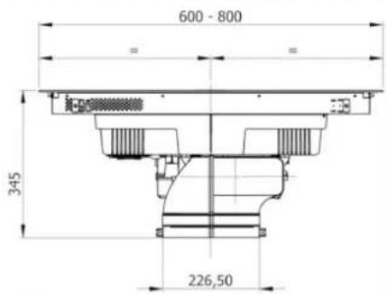

Fig 8C
C

natural_image
Pure architectural floor plan lines without any text, numbers, or symbolsFig 8D
D

natural_image
Pure architectural floor plan lines without any text, numbers, or symbolsnatural_image
Technical line drawing of a mechanical component with mounting base and internal channels (no text or symbols)natural_image
Technical line drawing of a mechanical device with an inset close-up showing internal components (no text or symbols)natural_image
Technical diagram of a mechanical assembly with a curved component and directional arrow (no text or symbols)
natural_image
Technical line drawing of a mechanical component with cross-sectional views and a person silhouette (no text or symbols)Fig. 20.1
natural_image
Technical line drawing of a mechanical component with cross-sectional views and a person in a trash bin (no text or symbols)3.3.C INDICAZIONI COSTRUTTIVE - SCARICO POSTERIORE
natural_image
Technical line drawings of various electronic components or connectors, including rectangular blocks and a grid-like structure (no text or symbols)natural_image
Line drawing of an electrical fuse box (no text or symbols)1x32 circuit breaker
220×240V
1+N+GDN

BI-PHASE
min. 4×1.5 mm ^2
2x16 circuit breaker
380×415V
3+N+GDN
THREE-PHASE
min. 5×1.5 mm²
3x16 circuit breaker
380×415V
3+N+GDN
MONO-PHASE
3×4 mm ^2
1x32 circuit breaker
220×240V
1+N+GDN

TIPOLOGIA CAVI:
H05VV-F
H05V2V2-F
H05RN-F
H05RR-F
(O CATEGORIE SUPERIORI)
Colore Connessione
| MONOFASE 3x4 mm ^2 | MONOFASE 5x1.5 mm ^2 | BIFASE 4x1.5 mm ^2 | TRIFASE 5x1.5 mm ^2 | |
| NERO L L1 L1 | ||||
| MARRONE L L L3 L3 | ||||
| BLU (GRIGIO) N N L2 | ||||
| BLU N N N N | ||||
| GIALLO/VERDE MESSA A TERRA | ||||
| PONTICELLO | ||||
natural_image
Three identical 3D-rendered kitchen utensils with no visible text or symbols, each accompanied by a small emoji (no text or symbols present)4.2.B DIMENSIONI DELLE PENTOLE
natural_image
Simple line drawing of a boat on a platform with a vertical rod and arrow, no text or symbols present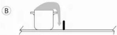
natural_image
Simple line drawing of a pot with a downward arrow and a black object on a horizontal surface (no text or symbols)
natural_image
Simple line drawing of a cooking process with a pot and tray, no text or symbols presentnatural_image
Pure diagram of a rectangular object with a downward arrow, no text or symbols present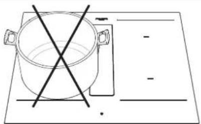
natural_image
Simple line drawing of a cooking pot with crossed-out pan and empty plate (no text or symbols)
natural_image
Simple line drawing of a cooking pot on a rectangular board with two crossed lines (no text or symbols)natural_image
Technical diagram of a refrigerator interior showing fan, vent, and water drop system (no text or labels)
ATTENZIONE
4.3 INDUCTION HOB 16
4.3.A COOKING ZONE DISPLAY 16
4.3.B HOB FEATURES 16
4.3.C HOB CONFIGURATION 16
4.3.D HOB OPERATION 20
4.4 EXTRACTION 23
4.4.A PRELIMINARY INSTRUCTIONS 23
4.4.B EXTRACTOR OPERATION 24
CONTENTS PAGE
5 - MAINTENANCE AND CLEANING 26
5.1 CLEANING THE EXTRACTOR INDUCTION HOB 26
6 - TROUBLESHOOTING 28
6.1 ERRORS / FAULT FINDING 28
6.1.A MOTOR SAFETY 28
6.2 CUSTOMER SERVICE 28
7 - PUTTING OUT OF SERVICE 30
7.1 DECOMMISSIONING 30
7.2 DISASSEMBLY 30
7.3 ENVIRONMENTAL PRESERVATION 30
7.4 DISPOSAL 30
These operating instructions describe the appliance and its use. This manual is an integral part of the appliance and must therefore be kept with care and must ALWAYS accompany it, even if it is passed on to another owner or user or transferred to another installation.
The appliance may differ in appearance from that illustrated in the drawings in this manual, however the instructions for installation, use and maintenance remain the same.
The manufacturer is committed to continuous improvement.
For this reason, the text and illustrations in this manual may be changed without notice.
• The appliance is manufactured to current safety standards.
- The appliance may not be used for any other purpose than the one for which it was built, i.e. as an extractor induction hob for cooking food and extraction of cooking fumes, installed in household kitchens.
- Any liability of the manufacturer for damage caused to persons, animals or property due to incorrect installation, maintenance or improper use is excluded.
- Before connecting the appliance to the mains supply, check the nameplate (located on the underside of the appliance) to ensure that the voltage and wattage correspond to those of the mains supply and that the connection socket is suitable. If in doubt, consult a qualified electrician.

CAUTION
Before any cleaning or maintenance operations or during thunderstorms, disconnect the appliance, setting the system's main switch to "off" (Fig.1) or pulling out the plug (Fig.2).
Fig. 1
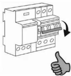
natural_image
Illustration of an electrical circuit breaker with a hand giving a thumbs-up gesture (no text or symbols)Fig. 2

- When the extractor hob is in operation, the parts of the extractor hob adjacent to the induction plates may also become hot.
- There is a possibility of fire if cleaning is not carried out according to the instructions.
- The appliance must not be cleaned with steam or high pressure appliances.
- Putting any objects through the glass intake flap (Fig.3) is prohibited.
- Do not use the appliance to heat the room.
- Make sure that the electrical connections of other appliances in the immediate vicinity do not come into contact with the hot appliance.
- Pulling, unplugging or twisting the electrical cables coming out of the appliance is prohibited, even if it is disconnected from the mains supply.
- Hob hoods and other cooking fume extractors can adversely affect the safe operation of appliance that burn gas or other fuels (including those in other rooms) due to the return flow of combustion gases. These gases can potentially cause carbon monoxide poisoning. After installation of a hood or other kitchen fume extractor, the operation of gas appliances with flow should be tested by a competent person to ensure that no return flow of combustion gases occurs.
• Cooking with a flame is prohibited. - To avoid any unwanted disturbance on the control panel ("TC" Touch Control), place suitable pots centred to the marked points in the glass-ceramic surface (Fig. 4).
Precautions before use.
- Unpack all materials.
- Appliance installation and connection must be carried out by authorised specialists.
- The manufacturer cannot be held liable for damage caused by installation or connection errors.
- To be used, the appliance must be properly equipped and installed in a kitchen unit and on an adapted and approved work surface.
- This appliance is intended exclusively for cooking food and excludes any other domestic, commercial or industrial use.
- Remove all labels and stickers from the ceramic glass.
- Do not change or alter the appliance.
- The cooking plate may not be used as self-supporting or as a work surface.
- The appliance must be earthed and connected in accordance with local standards.
- Do not use extension cords or power strips to connect it.
- The appliance may not be used above a dishwasher or tumble dryer: steam can damage electronic appliances.
Fig. 3
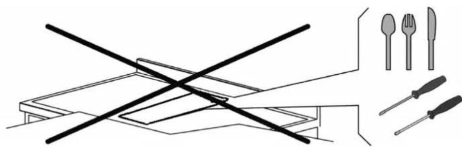
natural_image
Illustration of a table with crossed cutlery and four kitchen utensils (shrimp, fork, knife) arranged on a table (no text or symbols)- The appliance is not designed for use with an external timer or a separate remote control system.
Using the appliance
• After use, switch off the hob via its control device and do not rely on the pot detector.
- Switch off the heating zones after use.
- Keep an eye on cooking with grease or oils that could ignite quickly.
• Take care not to burn yourself during or after using the appliance.
- Make sure that no fixed or movable cables from any appliance come into contact with the hot glass or pots.
- Magnetic objects (credit cards, floppy disks, calculators) must not be placed near the inserted appliance.
- Metal objects such as knives, forks, spoons and lids must not be placed on the hob surface as they can become hot.
- In general, do not place metal objects except heating containers on the glass surface. In the event of unexpected or residual overheating, these can heat up, melt or even burn.
- Never cover the appliance with a cloth or protective sheet. It may become very hot and catch fire.
- This appliance may only be used by children aged 10 years and over. Persons with reduced physical, sensory or mental capabilities or lack of experience and knowledge must be supervised or instructed in the safe use of the appliance and understand the dangers.
• Children must not play with the appliance.
- Cleaning and maintenance by the user must not be carried out by children without supervision.
Precautions against damaging the appliance
- The bottoms of rough cookware or damaged pots (not enamelled cast-iron pots) can damage the ceramic glass.
- Sand or other abrasive materials can damage the ceramic glass.
- Avoid dropping objects, even small ones, on the ceramic glass.
- Do not hit the edges of the glass with pots.
• Make sure that the appliance's ventilation works in accordance with the manufacturer's instructions. - Do not place or leave empty pots on the glass-ceramic hobs.
- Sugar, synthetic materials or aluminium foil must not come into contact with the heating zones. These can cause breakage or other alterations to the glass-ceramic by cooling: switch on the appliance and remove them immediately from the hot heating zone (be careful: do not burn yourself).

WARNING
Unattended cooking on a hob with grease or oil can be dangerous and cause fires.

CAUTION
The cooking process must be supervised. A short-term cooking process must be constantly monitored.

CAUTION
Fire hazard: do not place objects on the cooking surface.
- Never place hot containers on the control panel.
- Adequate ventilation must be ensured at the front and rear of the cabinet so that air can circulate.
- If a drawer is located under the built-in appliance, make sure that the clearance between the contents of the drawer and the bottom of the induction hob is large enough (30 mm). This is essential to ensure proper ventilation.
- Never place flammable objects (e.g. sprays) in the drawer under the glass-ceramic hob. Any cutlery drawers must be heat-resistant.
Fig. 4
Precautions in case of appliance failure.
- If a defect is found, switch off the appliance and interrupt the power supply.
- If the ceramic glass is broken or cracked, disconnect the appliance and contact after-sales service.
- Repairs must be carried out by specialists. Do not open the appliance yourself.

WARNING
If the surface is cracked, switch off the appliance to avoid the possibility of electric shock.
Other protections
- Note that the cookware/container is always centred on the cooking zone drawn on the hob.
- The magnetic field may affect the operation of pacemakers. We recommend that you ask your dealer or doctor for information.
- Do not use aluminium or synthetic containers: they could melt in cooking zones that are still hot.
- NEVER attempt to extinguish a fire with water but switch off the appliance and cover the flame, e.g. with a lid or fire blanket.

CAUTION
THE USE OF POOR QUALITY POTS OR ANY NON-MAGNETIC POTS INDUCTION ADAPTER PLATE WILL RESULT IN A BREACH OF WARRANTY.
IN THIS CASE, THE MANUFACTURER CANNOT BE HELD LIABLE FOR ANY DAMAGE CAUSED TO THE HOB AND/OR ITS SURROUNDINGS.
3.1 AIR HANDLING
This extraction system enables the handling of cooking fumes. The system can be used in extraction or filter mode (active carbon filter kit supplied separately).
Extractor (external evacuation).
The cooking fumes are expelled to the outside through the pipe (not supplied with the hood) connected to the motor exhaust fitting.


CAUTION
Under no circumstances should the pipe be connected to combustion exhaust ducts (stoves, boilers, burners, etc.).
natural_image
Technical line drawing of a mechanical assembly inside a 3D enclosure, showing internal components and directional arrows (no text or symbols)The use of long pipes with many bends, corrugated and with a smaller cross-section than the motor outlet will cause a decrease in extraction performance and a possible increase in noise.
Filter (internal recycling).
The fumes pass through activated carbon ceramic odour filters (can be ordered separately as an accessory), to be purified and recycled in the kitchen environment.

natural_image
Technical line drawing of a mechanical assembly or housing component (no text or symbols visible)3.2 PRELIMINARY INSTRUCTIONS
Read the entire instruction manual before installing and using the equipment.
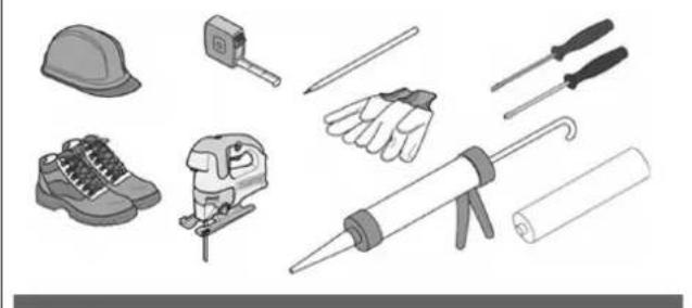
Safety equipment and a series of tools are required for equipment installation, as shown in Fig.5.
Fig 5
natural_image
Collection of various hand tools and equipment including a hard hat, saw, screwdriver, rubber can, and foot (no text or symbols visible)The extractor hob is equipped with all the fixings necessary for its installation and suitable for most furniture.

CAUTION
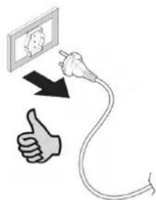
Check the minimum cabinet dimensions for installation considering the footprint of the appliance shown in Fig. 6 and Fig. 7.
Fig 6
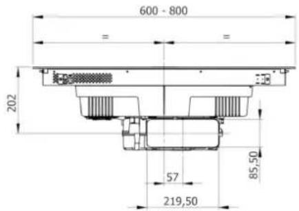
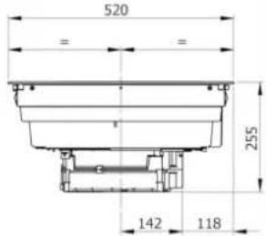
Fig 8A
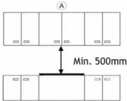
Fig 8B
B
natural_image
Simple line drawing of a cabinet with doors and a horizontal bar, no text or symbols presentFig 7


Fig 8C
C

natural_image
Pure architectural floor plan lines without any text, numbers, or symbolsFig 8D
D

natural_image
Pure architectural floor plan lines without any text, numbers, or symbolsThe furniture cladding must be treated with heat-resistant glue (100°C), otherwise the shape and colour may change due to lower heat resistance.
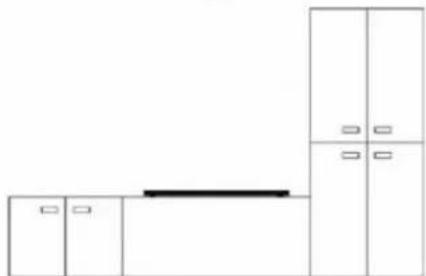
Ideally, the appliance should be installed without column cabinets or walls on both sides (Fig.8-A). Column cabinets or walls may only be placed on one side of the appliance (Fig.8-B and Fig.8-C). Under no circumstances may cabinets or walls be placed higher than the appliance on both sides (Fig.7-D), for protection against fire hazards. Wooden decorations are not permitted.
We recommend that you install the appliance only after the wall cabinet has been mounted to avoid possible damage to the glass top.
The safety clearance between the hob and any furniture positioned above it must be at least 500 mm. (Fig. 8-A).
natural_image
Technical line drawing of a mechanical component with a grid-like structure and mounting base (no text or symbols)Place the 4 centring springs in the 4 corners of the metal base as shown above.
3.3 INSTALLATION
The installer will find the items shown below when the box is opened, to be installed as described on these pages.
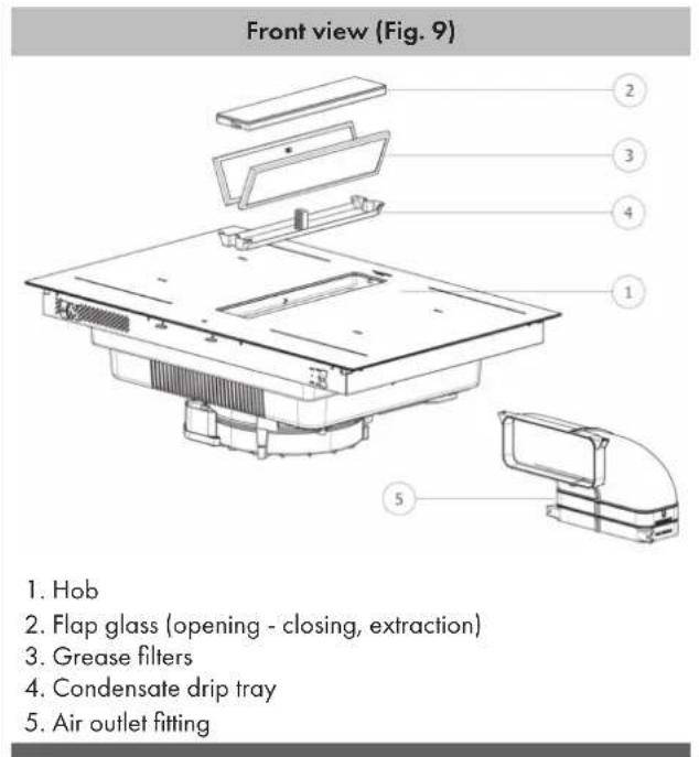
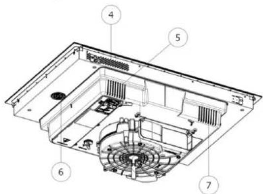
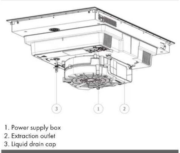
Rear view (Fig. 10)
3.3.A INDUCTION HOB INSTALLATION
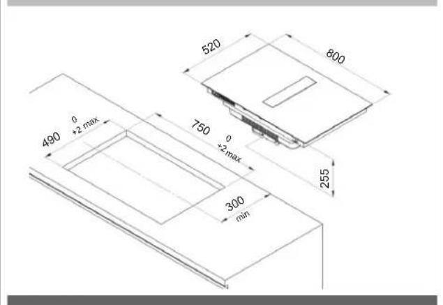
To leave the necessary clearance for the air piping, it is important to install the induction hob with the centreline more than 300 mm from any wall at the rear.
The induction hob can be installed in two ways, either resting on the worktop or flush with the worktop.
To perform WORKTOP INSTALLATION, drill holes in the hob as illustrated:
Fig. 11 - 60cm worktop
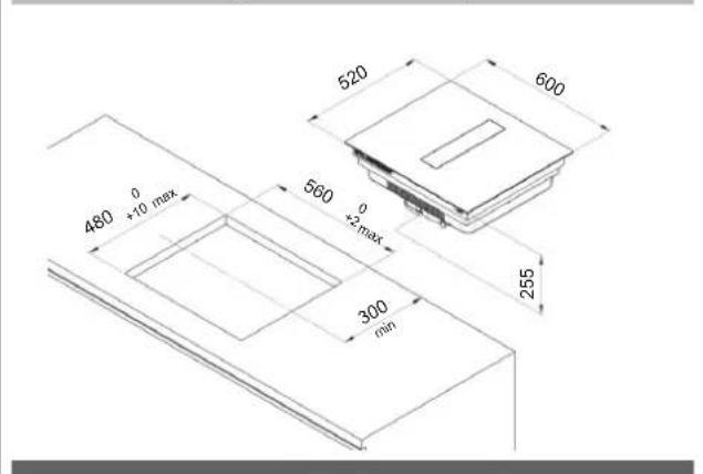
Fig. 12 - 80cm worktop
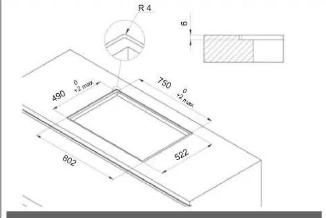
To perform FLUSH INSTALLATION, drill the top and mill the worktop along the edge of the installation hole, respecting the measurements indicated:
Fig. 13 - 60cm worktop
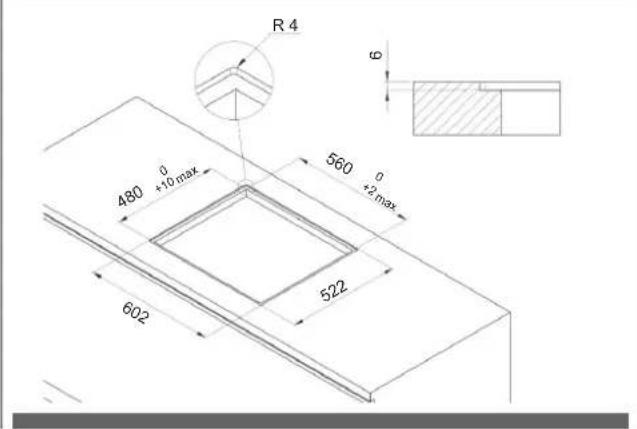
Fig. 14 - 80cm worktop
Installation is under the sole responsibility of the specialists. The installer must comply with the legislation and standards in force in his/her country of origin. To protect the cut edge of the cabinet, apply a coat of special paint or sealant. Special care must be taken when applying the adhesive gasket supplied with the hob to prevent leaks in the supporting cabinet. This gasket ensures a proper seal when used in combination with smooth work surfaces.
How to attach the gasket:
The gasket supplied with the hob prevents all liquid ingress into the cabinet. It must be installed carefully in accordance with the following drawing.
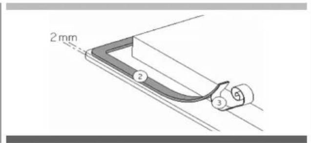
Attach the gasket (2) two millimetres from the outer edge of the glass after removing the protective film (3).
Assembly - installation:
- Make sure that there is a distance of 50 mm between the hob and the wall or sides.
- Ideally, the hob should be installed with plenty of space on both sides. There could be a wall at the back and high units or a wall on one side. On the other side, however, no unit or divider should be higher than the hob.
- The cabinet or stand in which the hob is to be installed, as well as the edges of the cabinet, the laminate coatings and the glue used to fix them, must be able to withstand temperatures of up to 100°C.
- Do not install the hob above a non-ventilated oven or dishwasher.
Secure the air connection (Fig. 15) on the extractor fan outlet with the two screws provided.
Fig. 15
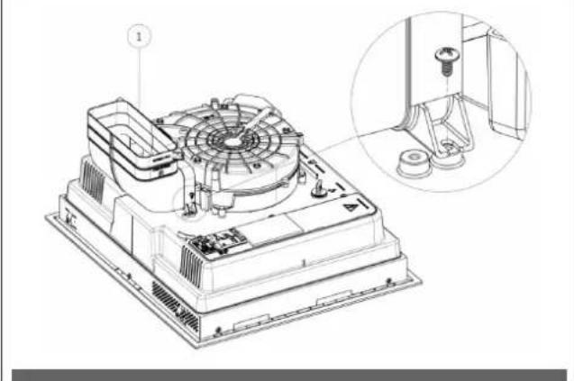
natural_image
Technical line drawing of a mechanical fan assembly with an inset close-up showing a component detail (no text or symbols present)Set down the hob (Fig. 16).
Fig. 16

natural_image
Technical diagram of a mechanical assembly with a curved component and directional arrow (no text or symbols)Adequate ventilation must be ensured at the front and rear of the cabinet so that air can circulate through the various air intakes as indicated below in the figures:
Fig. 17 - 60cm worktop. (5 air intakes)
- If a drawer is placed under the hob, maintain a clearance of at least 30 mm between the ventilation of the underside of the hob and what is stored inside the drawer to ensure good air circulation and cooling of the appliance.
- If a drawer is placed under the hob, avoid placing flammable objects (e.g. sprays) or non-heat-resistant objects in this drawer.
- The connection cable must not be subjected to any mechanical stress after installation, e.g. from a drawer.
Only use the hob guards designed by the manufacturer of the cooking appliance or indicated by the appliance manufacturer in the operating instructions as suitable or hob guards built into in the appliance. The use of inappropriate guards can lead to accidents.
3.3.B CONSTRUCTION INSTRUCTIONS - DISCHARGE ON BASEBOARDS
To allow correct housing of the discharge pipe, if it is fitted under the cabinet baseboard. The base must be discharged as shown in Fig. 19 and the back panel removed if necessary.
Introduction of this extraction system results in a maximum possible length for any drawers provided under the hob of approximately 450 mm.
The depth of the drawers is indicative and based on a cabinet base with standard dimensions.
Fig. 19
Fig. 18 - 80cm worktop. (7 air intakes)
Fig. 19.1
natural_image
Technical line drawing of a mechanical component with cross-sectional views and a person silhouette (no text or symbols)Fig. 20.1

natural_image
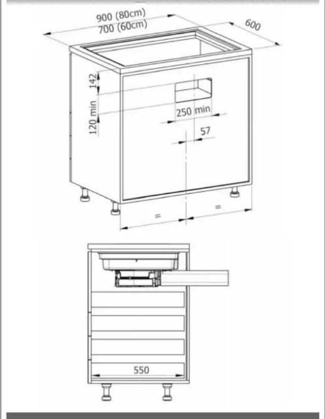
Technical line drawing of a mechanical component with cross-sectional views and a person in a trash bin (no text or symbols)3.3.C CONSTRUCTION INSTRUCTIONS - REAR DISCHARGE
To allow air to be discharged from the rear, the base of the cabinet must not be discharged. The back panel must be discharged as shown in Fig. 20 or, if necessary, removed.
The maximum possible length for any drawers provided under the hob of approximately 550mm.
The depth of the drawers is indicative and based on a cabinet base with standard dimensions.
Fig. 20
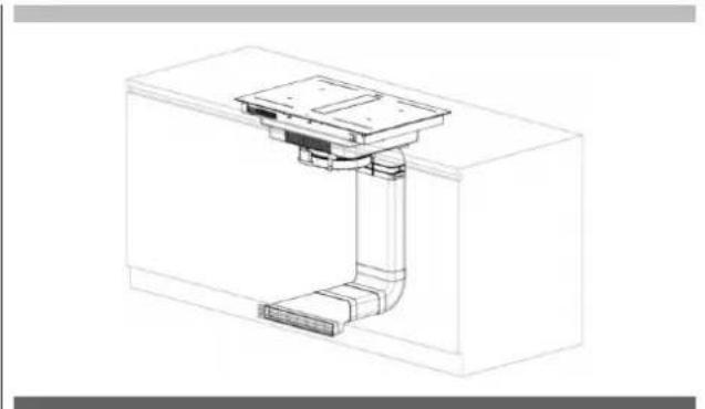
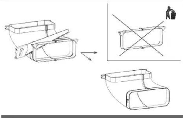
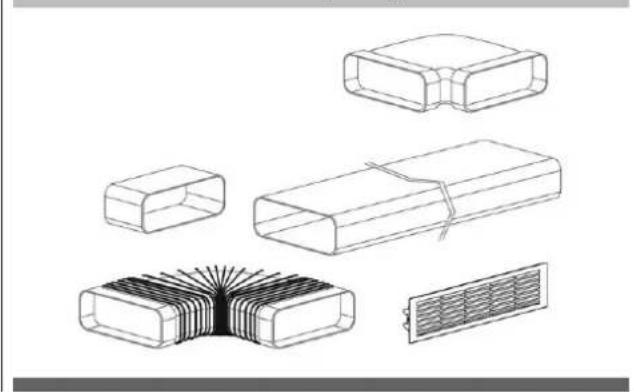
3.3.D AIR OUTLET PIPE ASSEMBLY
In order to bring the air outlet to the desired position, pipes must be installed using separately purchased fittings (Fig. 21). All piping must pass under the base of the cabinet, in the baseboard riser space.
Fig. 21 (Consult the Piping Installation Kit sheet, Kit sold separately)
natural_image
Technical line drawings of various electronic components including resistors, capacitors, and a heat sink (no text or symbols)3.4 ELECTRICAL CONNECTION
The electrical connection must ONLY be made by specialised technicians. The electrical protection of the electrical connection upstream of the appliance must comply with the standards in force.

CAUTION
Make sure that the voltage (V) and frequency (Hz) indicated on the nameplate inside the appliances correspond to those available at the installation site.
Any changes that may be necessary to the electrical system in order to install the hood must only be carried out by competent persons. After installation, insulated and current-carrying parts must be protected against contact.

CAUTION
If the electrical connection is made incorrectly or not in accordance with standards, parts of the appliance may become damaged and the warranty shall not cover this.

CAUTION
Disconnect the appliance from the mains before any work is carried out (Fig. 1 - Fig. 2 WARNINGS chapter).
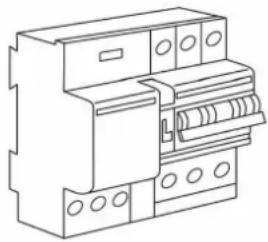
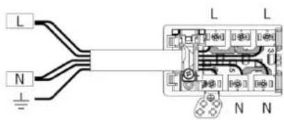
These appliances must be connected to an earthed system. The appliance must be connected to the mains power system, interposing an omnipolar switch that ensures mains disconnection, with a contact opening distance that allows complete disconnection under the conditions of overvoltage category III in accordance with the installation rules (Fig. 22).
Fig. 22
natural_image
Line drawing of an electrical fuse box (no text or symbols)The earth connection (yellow-green cable) must not be interrupted under any circumstances.
The power cable must be long enough to connect the appliance recessed in the cabinet to the mains supply. If the power cable is damaged, it must be replaced in order to prevent any risks.
If the mains cable is damaged, it must be replaced by the manufacturer or its technical customer service or a similarly qualified person in order to prevent any risks.

CAUTION
We cannot be held liable for any accidents resulting from an incorrect connection or which may result from use of an appliance which has not been connected to earth or which has been fitted with a defective earth connection.
Protection against live parts must be ensured after installation.
Connection to the mains must be made using an earthed plug or an omnipolar circuit-breaking device with a contact opening of at least 3 mm.
The power cable must be positioned so that it does not touch hot parts of the hob or anything else.
Use a power cable with a conductor cross-section suitable for power up to 7360 Watts to connect the appliance to the mains.
Note: the product is equipped with a Power Limitation function that allows you to set a maximum absorption threshold (Kw). This setting must be made when the product is connected to the mains or when the mains is reconnected (within 2 minutes). Size the electrical system protection according to the selected Power Limitation level. See this manual in the Operation section for the Power Limitation setting sequence.
At no point should the cable reach a temperature of 50^ C above the ambient temperature.
The appliance is intended to be permanently connected to the mains.

CAUTION
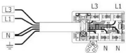
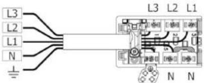
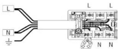
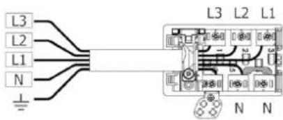
Comply with the following connection diagram (Fig. 23):
Fig. 23
MONO-PHASE
min. 5×1.5 mm²
1x32 circuit breaker
220×240V
1+N+GDN
BI-PHASE
min. 4×1.5 mm²
2x16 circuit breaker
380×415V
3+N+GDN
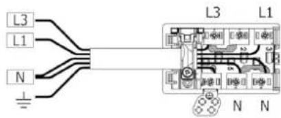
THREE-PHASE
min. 5×1.5 mm²
3x16 circuit breaker
380×415V
3+N+GDN
MONO-PHASE
3×4 mm ^2
1x32 circuit breaker
220×240V
1+N+GDN
CABLE TYPE:
H05VV-F
H05V2V2-F
H05RN-F
H05RR-F
(OR HIGHER CATEGORIES)
Colour Connection
| MONO-PHASE 3x4 mm ^2 | MONO-PHASE 5x1.5 mm ^2 | BI-PHASE 4x1.5 mm ^2 | THREE-PHASE 5x1.5 mm ^2 | |
| BLACK L L1 L1 | ||||
| BROWN L L L3 L3 | ||||
| BLUE (GREY) N N L2 | ||||
| BLUE N N N N | ||||
| YELLOW/GREEN | EARTHING | |||
| BRIDGE | ||||
4.1 DESCRIPTION OF THE EXTRACTOR INDUCTION HOB
4.1.A TECHNICAL FEATURES
Fig. 24
Power level detail:
The total power limitation (Power Limitation, see Operation paragraph) when the heaters operate simultaneously can be configured according to the following values:
2800W - 3000W - 3680W - 4000W - 4500W - 5000W - 6000W - 7400W
| Parameters Value | |
| Multi-phase connection voltage 380 - 415V 2N / 3N | |
| Mono-phase connection voltage 220 - 240V | |
| Frequency 50Hz / 60Hz | |
| Max absorbed power 7.4 kW | |
| Fuse / connection to the three-phase network 3 x 16A | |
| Fuse / connection to the bi-phase network 2 x 16A | |
| Fuse / connection to the mono-phase network 1 x 32A | |
| Dimensions (width x depth x height) | 60cm. 600 x 520 x 255mm80cm. 800 x 520 x 255mm |
| Net weight (hob only) 60cm. 19.0 kg. / 80cm. 20.0 kg. | |
| Gross weight (complete with packaging) 60cm. 27.5 kg. / 80cm. 29.5 kg. | |
| Hob | |
| Surface material Glass-ceramic | |
| Power level 1 - 9, P | |
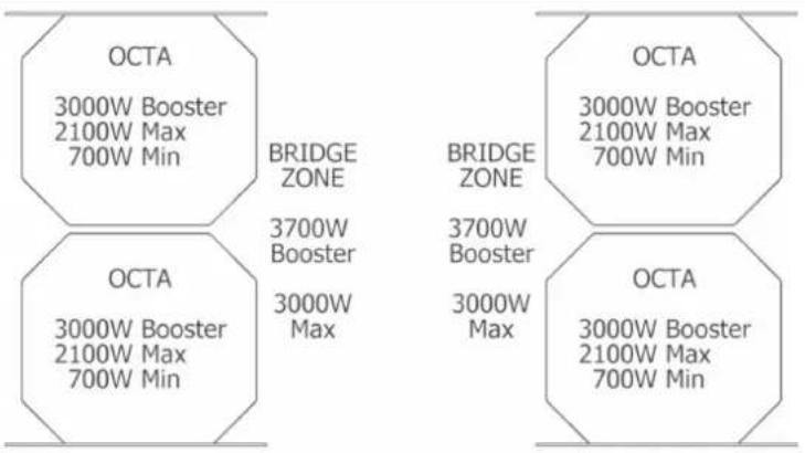
| Cooking zone dimensions OCTA 210 x 190mm | |
| Min-max level (booster) cooking zone power 700W-2100W (3000W) | |
| Hob energy consumption (pot dimensions) | |
| Left front cooking zone (FL) (?) 187.3 Wh/Kg | |
| Front right cooking zone (FR) (?) 187.3 Wh/Kg | |
| Rear left cooking zone (RL) (?) 187.3 Wh/Kg | |
| Rear right cooking zone (RR) (?) | 187.3 Wh/Kg |
| Total (on average) | 187.3 Wh/Kg |
| Extraction system | |
| Power level | 1 - 9, P |
| Recirculating air filter | |
| Ceramic filter regeneration duration | 120 hours |
4.1.B MAIN EXTRACTOR HOB CONTROL FEATURES
Fig. 25
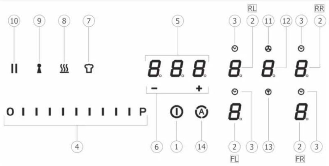
CONTROL PANEL ("TC" TOUCH CONTROL)
Touch keys / Display
- Hob/extraction system ON/OFF
- Cooking zone selection / Cooking zone display:
2FL Front Left
2FR Front Right
2RL - Rear Left
2RR -Rear Right
- Cooking zone timer activation / Cooking zone time on indicator
- Cooking power level and extraction speed (power) Increase/Decrease /Cooking power level and extraction speed (power) display
- Independent Timer activation / Independent Timer display / Cooking zone timer
- Independent Timer time Increase/Decrease / Cooking zone timer display
- "Chef Cook" function activation
- "Warming" function activation
- "Keylock" function activation
- "Pause" function activation
- Extractor on indicator in after-run fan mode
- Extractor selection / activation / display
- Filter saturation reset
- Automatic extractor function activation
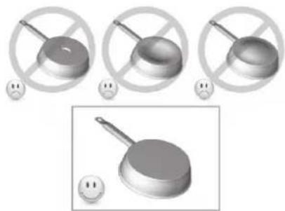
4.2 COOKING VESSELS
4.2.A QUALITY OF POTS
Only use pots bearing the symbol
Suitable materials: steel, enamelled steel, cast iron, ferromagnetic stainless steel, aluminium with ferromagnetic bottom.
Unsuitable materials: aluminium and stainless steel without ferromagnetic bottom, copper, brass, glass, ceramics, porcelain.
Manufacturers specify whether their products are compatible with induction.
To check whether pots are compatible:
- Put some water in the cookware placed on an induction heating zone set to the lowest level. This water should heat up in a few seconds.
• A magnet attaches to the bottom of the pot. - Some pots may make noise when placed on an induction cooking zone. This noise does not mean any fault on the appliance and does not affect cooking.
Fig. 26
natural_image
Three identical 3D-rendered objects with crossed handles and a frying pan, each with a small smiley face below (no text or symbols)4.2.B DIMENSIONS OF POTS
The minimum recommended diameter of the pots to be used is:
| Function active Minimum Pot diameter |
| Single cooking zone ∅ 110mm |
| “Bridge” cooking zone ∅ 230mm |

CAUTION
Pot detection is not guaranteed for the following diameters:
| Function active Minimum Pot diameter | |
| Single cooking zone from > = 80mm to < 110mm | |
| “Bridge” cooking zone from > = 190mm to < 230mm |
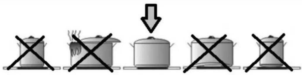
The bottom of the pot must not be larger in diameter than the surface of the cooking zone and must never encroach on the central glass flap.
For best efficiency of the hob, position the suitable cookware well centred in relation to the marked cooking zone on the glass-ceramic surface.
4.3 INDUCTION HOB

IMPORTANT
All hob functions are designed to comply with the strictest safety regulations.
For this reason:
- Some functions do not activate or deactivate automatically when there are no pots on the hob or when the pots are poorly positioned. In other cases, activated functions deactivate automatically after a few seconds when the selected function requires an additional setting that is not given (e.g.: "Turn on hob" without "Select cooking zone" and levels, or the "Key Lock" or the "Timer" function).
- Caution! In case of (for example) prolonged use, cooking zone power-off may not be immediate because it is in the cooling phase; the symbol "H" appears in the cooking zone display to indicate that you are in this phase.
- Wait for the display to switch off before approaching the cooking zone.
4.3.A COOKING ZONE DISPLAY
The following are indicated in the cooking zone displays:
| Cooking zone on | 0 |
| Power levels | 19-P(P=Power Booster) |
| Residual heat display | H |
| Pot detector | y |
| Bridge function on | n |
| Warning function on | o |
| Pause function | II |
| Chef Cook function | (2-5-6-8) |
| Key Lock function |
| Automatic Extraction function | |
| Timer function | |
| Timer function(only with touch off) | |
| Filter saturation |
4.3.B HOB FEATURES
- Pot Detector:
The hob automatically detects the presence of pots on the cooking zones.
- Safety Shut Down:
For safety reasons, each cooking zone has a maximum operating time that depends on the power level set.
| COOKING LEVEL MAXIMUM OPERATING TIME (Hours) | |
| WARMING 2 | |
| 1 | 6 |
| 2 | 6 |
| 3 | 5 |
| 4 | 5 |
| 5 | 4 |
| 6 1.5 | |
| 7 1.5 | |
| 8 1.5 | |
| 9 1.5 | |
| P 5 (MINUTES) | |
• Residual Heat Indicator:
When one or more cooking zones are switched off, the presence of residual heat is signalled with a visual signal with the symbol "H" on the display of the corresponding zone.
- Beep
Acoustic function activation signal
4.3.C HOB CONFIGURATION
Before use, the hob's Touch Control Panel can be set to suit your personal requirements.
There are two types of Menus: User Menu and Service Menu.
USER MENU
From the User Menu, you can change certain control panel functions such as brightness, key sound volume, information sound volume, control panel lighting, timer animation, etc. To access the User Menu, the control panel (hob control display) must be in standby mode (off).
Accessing the User Menu:
- Touch ON/OFF to switch on the Control Panel, then tap ON/OFF again within 3 seconds to switch off.
- The || (Pause) key starts pulsing for up to 60 seconds (if no action is taken, the menu entry attempt is automatically exited after these 60 seconds).
- Press the || (Pause) key without releasing it.
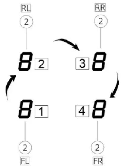
- Press the display of each cooking zone clockwise as shown in Fig. 27, again without releasing the Pause key, starting from the front left cooking zone display 2FL (1-2-3-4).
Fig. 27
flowchart
graph TD
    A["RL 2"] --> B["8 2"]
    B --> C["3 8"]
    C --> D["8 1"]
    D --> E["4 8"]
    E --> F["2 FR"]
    G["RR 2"] --> H["8"]
    H --> I["3"]
    I --> J["8"]
    J --> K["2 FL"]
• Each key press will be confirmed by an acoustic signal (beep).
- Release the || (Pause) key that has pulsed.
- The user menu is active.
- The left rear cooking zone display (2RL) intermittently shows "U0" ("U" and "O"). Select the menu item you wish to view/change using the slider (4) as summarised in the table Fig. 27.
For example, to go to U4 (display brightness), press on the 2RL display and with the touch slider select level 4 (the third slider bar from the left) 0 1 1 1.
U4 now flashes intermittently.
- At this point, select the front left display (2FL), where the set value and any possibilities are displayed.
In the example of the brightness setting, after selecting the front left display (2FL), all bars up to 9 will appear on the slider and the display (2FL) will show the number with a permitted value, in this case from 0 to 9 (in other cases there may be fewer values, e.g. in U3 there are only values from 0 to 3)

Then the front left cooking zone display (2FL) will show the selected value of the respective selected element; you can then change the value by touching the slider.
Exiting the User Menu:
- Exit without saving: Touch the || (Pause) key. All changes are deleted.
- Exiting with Save Settings: Touch the power ON/OFF key for 2 seconds. Changes are saved.
Note: The user menu closes automatically if no operations are performed for 1 minute.
Overview of user menu items
The following table provides an overview of the user menu items:
| Left Rear Display (2RL) | Meaning Variable Front Left Display | (2FL) (Value Format) | Note | |
| U0 Power Adjustment (1.4-7.4)(if default setting C8=0)(step 0.1 kW)E.g. Power Adjustment (1.4-3.7)(if modified with setting C8=5) | Yes e.g. 7.4 | (default)e.g. 3.7 (if service menu setting C8 = 5) | ||
| U1 Filter setting: | Grease or carbon filter with or without a 5-minute after-run fan (after-run fan is extractor operation at level 1 after you have switched off the hob because you have finished cooking) | Yes 0,1,2,3 | (U1 DEFAULT= 0) | Filter:0-grease filter + after-run fan 5 min. (G)1-carbon filter + after-run fan 5 min. (F)2-grease filter without after-run fan (G)3-carbon filter without after-run fan (F) |
| U2 Volume for button tones | Yes 0,1,2,3 | (U2 DEFAULT= 3) | Volume setting for button tones:0: no button tones1: minimum volume2: half volume3: maximum volume | |
| U3 Volume for signal tones | Yes 0, 1, 2, | 3(U3 DEFAULT= 3) | Volume setting for beeps (e.g. when the timer expires):0: no button tones1: minimum volume2: half volume3: maximum volume | |
| U4 Display brightness | Yes 0, 1, 2, | 3, 4, 5, 6, 7,8, 9(U4 DEFAULT= 0) | Display brightness setting:0: maximum brightness....9: minimum brightness | |
| U5 Timer animation | Yes 0, 1 | (U5 DEFAULT= 1) | 0: No timer animation1: The timer is animated 10 seconds before expiry | |
| U6 Permanent pot detection | No | |||
| U7 Behaviour when the Timer expires | Yes 0, 1, 2 | 0: Buzz for 120 sec. | 1: Buzz for 10 sec.2: No tone | |
SERVICE MENU
The service menu is for service purposes only, except for certain "energy management" functions such as the maximum Power Level, which can be adjusted from the User Menu but is set by the Service Menu.
Accessing the service menu
When the hob is powered up, the symbol 📋 is active for a maximum of 2 minutes. This menu can be accessed whenever power is physically removed from the hob.
The special function key 📋 is flashing.
- Press the key 📋 without releasing it.
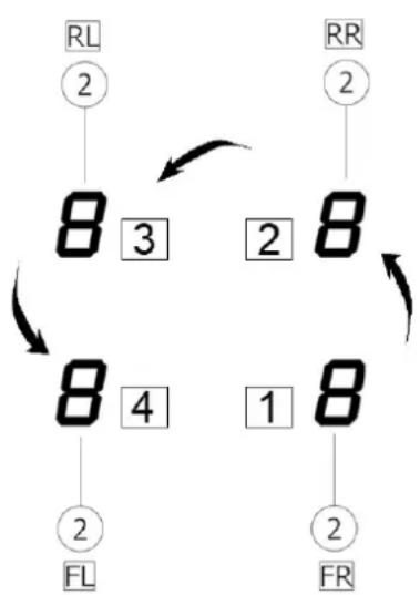
- Press each cooking zone display (2) counter-clockwise, as shown in Fig. 28, starting from the front right, 1-2-3-4 (1->2FR... 2->2RR... 3->2RL... 4->2FL).
Fig. 28
flowchart
graph TD
    A["RL\n②"] --> B["8 3"]
    B --> C["2"]
    C --> D["8"]
    D --> E["1"]
    E --> F["8"]
    F --> G["2"]
    G --> H["FL"]
    H --> I["2"]
    I --> J["FR"]
    J --> K["2"]
    K --> L["8"]
    L --> M["1"]
    M --> N["8"]
    N --> O["2"]
    O --> P["FL"]
    P --> Q["2"]
    Q --> R["FR"]
    R --> S["2"]
    S --> T["FL"]
    T --> U["2"]
    U --> V["FR"]
    V --> W["2"]
    W --> X["FL"]
    X --> Y["2"]
    Y --> Z["FR"]
• Each key press will be confirmed by an acoustic signal (beep).
- Release the key that has pulsed.
• The service menu is active.
- The left rear cooking zone display (2RL) intermittently shows "CO" ("C" and "O").
Selecting and changing menu values
- Select the Left Rear display (2RL) and with the slider, for example, touch the last dash and C9 will then flash (% dimming of displays not selected).
- Now press on the front left cooking zone display (2FL) where the value that can be set is then shown. 0111
- The selected menu item is displayed at full brightness.
• The other displays are dimmed. - Choose the value of the menu item via the slider, for example in this, C9, selecting the value 0 in the Front Left display (2FL). Press at the beginning of the slider to choose to dim the inactive displays by 10% compared to the maximum brightness of the selected controls.
Exiting the service menu
- Exit without saving: touch the key 📋. All changes are deleted.
- Exiting with Save Settings: touch the power ON/OFF key for 2 seconds. Changes are saved.
Note: The service menu closes automatically if no operations are performed for 2 minutes.
Overview of service menu items
The following table provides an overview of the service menu items reserved for Service.
Only the "energy management" functions that can be set and LED display dimming are indicated below:
| Left Rear Display (2RL) | Meaning Variable Front Left Display | (2FL) (Value Format) | Note | |
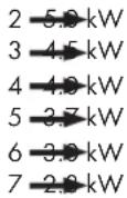
| C8 Maximum power Yes 0,1,2,3,4,5,6,7 | (C8 default=0) | Configuration already set:0->7.4 kW (default)1->6.0 kW2->5.0 kW3->4.5 kW4->4.0 kW5->3.7 kW6->3.0 kW7->2.8 kW | ||
| C9 Display LED Brightness Dimming Yes 0,1,2,3 | (C9 default=1) | 0->10%1->25% (default)2->40%3->66% |
Power Limitation (Total Power Limitation) function
This function lets you set a total power limitation of all active cooking zones in order to give a first constraint on the maximum absorption of the hob.
This first power constraint can be set from 7 choices as shown in the table.
This configuration must set while the hob is switched off (without pressing the ON/OFF key (1), when connecting the hob to the electrical mains or activating connection to the mains, within 2 minutes.
As default value C8 and 0, therefore with absorption constraint 7.4. It is still possible to enter the UO menu from the user menu, for example, and adjust the power value from 7.4 to 1.4 with steps of 0.1 kW.
If for example the service menu C8 was set to level 7, therefore the power setting from the user menu U0 would be adjustable from 2.8 up to 1.4 kW.
Proceed as follows:
- Press which will flash only for the first 2 minutes after the product is powered on
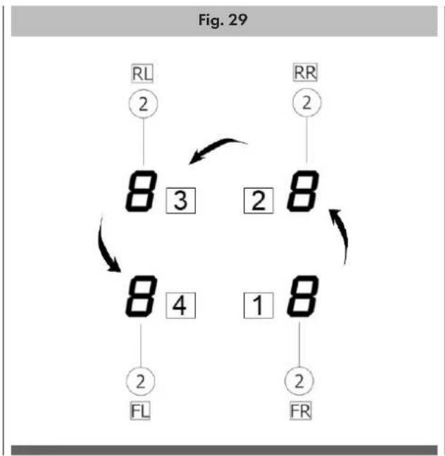
- Press and hold 📋 (7); press, one at a time, all the Selection/Display areas (2) of the cooking zones, counter-clockwise starting from the front right zone as indicated in Fig. 29 (1->2FR... 2->2RR... 3->2RL... 4->2FL):
flowchart
graph TD
    A["RL\n②"] --> B["8\n3"]
    B --> C["2\n8"]
    C --> D["8\n4"]
    D --> E["1\n8"]
    E --> F["2\nFL"]
    G["RR\n②"] --> H["8\n2"]
    H --> I["2\nFR"]
    I --> J["2\n2"]
    J --> K["2\n2"]
    K --> L["2\n2"]
    L --> M["2\n2"]
    M --> N["2\n2"]
    N --> O["2\n2"]
    O --> P["2\n2"]
    P --> Q["2\n2"]
    Q --> R["2\n2"]
    R --> S["2\n2"]
    S --> T["2\n2"]
    T --> U["2\n2"]
    U --> V["2\n2"]
    V --> W["2\n2"]
    W --> X["2\n2"]
    X --> Y["2\n2"]
    Y --> Z["2\n2"]
    Z --> A
    style A fill:#f9f,stroke:#333
    style G fill:#f9f,stroke:#333
    style L fill:#f9f,stroke:#333
    style M fill:#f9f,stroke:#333
    style N fill:#f9f,stroke:#333
    style O fill:#f9f,stroke:#333
    style P fill:#f9f,stroke:#333
    style Q fill:#f9f,stroke:#333
    style R fill:#f9f,stroke:#333
    style S fill:#f9f,stroke:#333
    style T fill:#f9f,stroke:#333
    style U fill:#f9f,stroke:#333
    style V fill:#f9f,stroke:#333
    style W fill:#f9f,stroke:#333
    style X fill:#f9f,stroke:#333
    style Y fill:#f9f,stroke:#333
    style Z fill:#f9f,stroke:#333
• A short beep will sound with each press.
- When all Displays (2) are pressed, the button can be released
Now:
- the Display (2) of the rear left zone (RL) will show the symbols "C" and "0" in alternating sequence.
- You can now perform programming:
- Select the Display (2RL)
- Then slide on the Selection bar (4) until the symbols "C" and "8" appear in the Display
- The following settable setting will appear on the Display (2FL):
0 7.4 kW (default setting)
1 6.0 kW
- To change the maximum power level (Power Limitation) setting:
- Select the Display (2) on the left front zone (FL).
- Then slide on the Selection bar (4) to set the new setting.
- To save the selection made, press the ON/OFF key(1) for 2 seconds; a prolonged beep will be emitted to confirm the setting.
4.3.D HOB OPERATION
The desired zone must be activated before selecting any function.
On / Off
The hob is switched on by touching the ON/OFF key (1) for a few seconds.
When you press and hold this key, all available functions will become visible for a few moments, after which only the main functions will remain active.
During hob use, the other functions will be activated and can be used. All available functions will be illuminated with low intensity, which will only increase when they are activated.
To switch off, touch the ON/OFF key (1) for a few seconds.

IMPORTANT
This function has priority over all others, so it is possible to switch off the hob at any time.
The hob switches off automatically after 20 seconds if all cooking levels are set to 0 and no operation is running.

IMPORTANT
MOTOR SAFETY
Following repeated opening and closing of the central flap, the electronics may temporarily block motor operation for safety reasons. This block lasts 5 minutes. At the end of the block, extraction will resume if the flap is still open and a valid extraction level is still set on the touch control.
Selecting cooking zones
Touch the Selection/Display area (2) corresponding to the desired cooking zone.
Power level: increase/decrease
The hob is equipped with 9 power levels.
Touch and slide your fingers along the Selection Bar (4) to increase or decrease:
→ to the right to increase the power level;
← to the left to decrease the power level.
The set power level will be displayed in the Selection/Display area (2)
Booster "P" function (Booster level)
The hob is equipped with an additional power level (Booster, in addition to level 9) which stays active for 5 minutes and then the power returns to the previous level.
This function is useful for heating or boiling a large quantity of water. To activate the Booster function, slide your finger along the Selection bar (4), past level 9, and activate the Booster function. The symbol "P" will appear on the display (2).
Caution: as the booster function can reach high temperatures, it should only be used for cooking with water. Oil or grease may start to burn if the Booster function is used.
Key Lock function
The Key Lock function locks the hob settings to prevent accidental tampering, leaving the functions already set active.
To activate it, touch the key ⚪(9); to deactivate it, tap the same key again.
If any other function is selected while Key Lock is active, the symbol will flash to indicate that the function is active. Deactivate the function to be able to operate the hob.
Child Lock function
The childproof lock is a feature to protect the hob from unwanted operation, for example by children. If it is locked, the hob can be switched on but the cooking zone, heating level and timer cannot be selected. The cooking zone display will show the symbol L. The childproof lock can only be activated once after switching on. Once activated and deactivated, the childproof lock cannot be activated a second time. The childproof lock can be activated again only after switching ON/OFF.
The childproof lock remains active even if the supply voltage is interrupted and recovered. It must be deactivated manually.
Activation:
- Switch on the hob (Key 1).
- Press and hold any cooking zone display (2) for 3 seconds. Then release the Display.
• The slider bar (4) lights up sequentially. - Slide the slider from 0 to 9 within 10 seconds.
- The childproof lock is activated. All the cooking zone displays will show L.
Deactivation:
- Switch on the hob (Key 1).
- Press and hold any cooking zone display (2) for 3 seconds. Then release the display.
• The slider bar (4) lights up sequentially.
Slide the slider from 9 to 0 within 10 seconds.
The childproof lock is deactivated. The hob switches to operating mode and can be operated normally.
Chef Cook function
The Chef Cook function allows you to prepare the cooking zones to operate at fixed levels without dispersing energy when there is no container placed on it.
As soon as a suitable vessel is placed in the cooking zones, these are the set values:
Front left zone: Level 2
Rear left zone: Level 5
Rear right zone: Level 6
Front right zone: Level 8
Notes: Power levels cannot be set by the user.
The operating time limit for the Chef Cook function is 2 hours.
While the Chef Cook function is active, the "pot detection" symbol is removed.
Activation:
- The hob is on.
- Touch the Chef Cook function key (7).
- Chef Cook mode is on.
- The cooking zone displays (2) and the power levels set from left to right in a clockwise direction (2-5-6-8).
Deactivation:
- Touch the Chef Cook function key (7).
- Chef Cook mode is off.
- The power levels for all cooking zones are set to 0.
Automatic Heat-Up function (Fast heat-up)
This function lets you heat up a cold pot with full heating power and automatically return to the desired cooking level. This enables faster heating with less risk of burning food. The function can be activated for power levels 1 to 8.
The time during which full power remains in the cooking zone depends on the cooking level selected and mentioned in the table below. The heating times are adapted for use with cold pots and common household food quantities.
Cooking Level Heat-Up Time (seconds)
| 1 48" |
| 2 2' 24" |
| 3 3' 50" |
| 4 5' 12" |
| 5 6' 48" |
| 6 2' |
| 7 2' 48" |
| 8 3' 36" |
| 9 Not available |
| P Not available |
Activation:
The pots are placed and the hob is active with a level between 1 and 8 for the cooking zone (2). Select the desired cooking zone. Touch and hold the cooking level on the selection bar (4) for 3 seconds.
A flashing alternating with the power set in the cooking zone will appear on the Display (2). Increasing the power level of the cooking zone, the Heat-Up function remains active with the new cooking time setting;
Decreasing the power level of the cooking zone, the Heat-Up function is deactivated.
Deactivation:
Touch and hold the cooking zone (2) for 3 seconds.
Fast heat-up is deactivated and the cooking zone is heated with the cooking level set before.
Alternative:
Select a cooking level lower than the level currently set for this cooking zone. Fast heat-up is deactivated. The cooking zone is heated with the new cooking level.
Warming function (Keeping warm)
This function allows already cooked food to be kept warm at a constant temperature.
This function is activated when the key (8) is pressed for the first time.
In the display (2) of the zone that is working with the "Warming" function active, the symbol will appear. If another cooking zone is selected at the same time, the symbol (8) will light up again and it will then be possible to activate the function for this zone as well. The function still remains active in the zone in which it has already been set, as indicated on the Display (2). Press the key (8) again to deactivate and switch off until bringing the level shown on the Display (2) to 0.
If the "Warming" function is active on multiple cooking zones, first select the desired zone via the Selection Display (2). This function can also be deactivated via the Selection Bar (4) by setting the Power Level to 0.
Pause function
The Pause function suspends any active function on the hob, bringing the cooking power to 0. To activate the function press || (Pause, 10) and the Cooking Zone Displays (2) will flash . To deactivate the function press || (Pause, 10), the key will start flashing; press another key within 10 seconds and the function will deactivate.
Deactivation restores the conditions of the hob before the pause and the hob continues to work with the same settings as previously set.
Caution: the hob must never be left unattended while the pause function is active.
If the Pause Function is not deactivated after 10 minutes, the hob will automatically switch off.
The Pause Function does not affect extraction.
Recall Function
This function lets you recover power levels, timer settings and fast heat-up after the hob has been unintentionally switched off.
If the hob is switched off and on again within 6 seconds, all previous settings (power levels, timer, fast heat-up) will be retrieved automatically.
The recall function cannot be deactivated by the user.
(The hob will return to the levels set before the pause).
Activation:
The hob has been switched off.
Switch the hob back on via ON/OFF (1).
The Pause || (10) key flashes for 6 seconds.
Touch the Pause || (10) key.
The recall function becomes active (a beep sounds). All previously set power levels, timers and fast heat-up are retrieved.
Stand-Alone Timer function
The Stand-Alone Timer function is a countdown independent of the cooking zones that emits an acoustic signal (beep) when it expires. The Timer is activated by pressing the central display (5); the two keys + / - (6) will appear for adjustment.
The Timer can be set when the Display shows “---”.
Set the desired duration of the timer via the + / - keys (6) and it will be shown in the Display (5).
The timer starts 6 seconds after activating this function (when no other control is pressed).
The stand-alone timer can be up to 600 minutes. The remaining time will be displayed in the Zone/Display (5); a beep will sound at the end of the countdown.
If the remaining time of the timer is less than 1 minute, it will be displayed in the format shown below and the dot will have a steady light:
There are two ways to switch off the Timer:
- Select (6) and set the duration of the Timer to 0.00 using +/-(6) or
- Press the ON/OFF key (1) twice
- The extraction timer stops the extraction and can only be set separately when the cooking zones are at zero (when the timer is started and then the hob is switched off, this time has priority over the after-fan function).
Cooking Zone Timer
The Cooking Zone Timer function is a countdown (maximum 119 minutes per zone) that can be set, even simultaneously, on each cooking zone.
At the end of the set time, the cooking zones switch off automatically and a beep is emitted.
To activate the function:
- Touch the Selection/Display area (2) (with a power level other than 0).
- Touch the key (3) corresponding to the cooking zone.
- The display will show "---" and the Timer can be set (with the + and - keys which will be displayed).
- Use the + / - keys (6) to set the duration of the timer, which is displayed in the Display area (5). The symbol ⬇ (3) flashes during programming.
The cooking zone timer starts after 6 seconds after activation (when no other key is pressed). To reset the cooking zone timer, press and hold the key √(3) again.
If desired, Timer programming can be repeated for multiple cooking zones.
Each cooking zone can have a different Timer set and the display (5) will show the countdown of the cooking zone selected at that moment √(3) (flashing) or the timer with the shortest time.
If no zone is selected, press on the Display (5) to view the Stand-Alone Timer countdown.
The countdown display is the same as for the Stand-Alone Timer (see previous paragraph).
When the timer has finished the countdown, a beep sounds and the cooking zone switches off.
To deactivate the Timer:
- Select the cooking zone (2) then touch the key ⏻ (3) and set the Timer duration to 0.0 using the keys +/ - (6)
Bridge function
This function allows both cooking zones to work simultaneously, forming a single cooking zone with the same power level.
This function allows even cooking with large pots.
The front "Primary" cooking zone can be used in combination with the corresponding rear "Secondary" zone.
The function is available on all cooking zones:
2FL (primary) + 2RL (secondary)
2FR (primary) + 2RR (secondary)
Bridge function activation:
- Select a cooking zone and set it to a value greater than 1, then
- Select the two cooking zones you want to use at the same time.
- The "Secondary" cooking zone Display (2) will show the symbol "II".
- Use the Selection bar (4) to set the operating Level (Power), which will be shown on the "Main" cooking zone Display (2).
Deactivate the Bridge Function:
Select the 2 cooking zones at the same time.

IMPORTANT
During the Bridge Function, the cooking zones are considered a single cooking area and therefore, if the Timer is active.
Cooking Zones, when this expires both cooking zones to switch off automatically.
Power table
| Power Level Type of cooking Recommended use | |||
| Maximum | Booster Fast Heat-up | Ideal for quickly raising the temperature | of food toa rapid boil in the case of water or quickly heating cooking liquids |
| 8-9 Frying, boiling | Ideal for browning, starting cooking, frying | frozen products, boiling quickly | |
| High | 7-8 Browning, sautéing | boiling, grilling | simmering, cooking and grilling(for short duration, 5-10 minutes) |
| 6-7 Browning, cooking | stewing, sautéing, grilling | Ideal for sautéing, light simmering, cooking and grilling (for medium duration, 10-20 minutes), preheating accessories | |
| Medium | 4-5 Cooking, stewing | sautéing, grilling | Ideal for stewing, maintaining gentle simmering, cooking (for long duration), blending pasta |
| 3-4 | Cooking, simmering, thickening, blending | Ideal for prolonged cooking (rice, sauces, roasts, fish) in the presence of accompanying liquids (e.g. water, wine, broth, milk), blending | |
| 2-3 Cooking, simmering, thickening, blending | blending | Ideal for prolonged cooking (volumes under one litre: rice, sauces, roasts, fish) in the presence of accompanying liquids (e.g. water, wine, broth, milk) | |
| Low | 1-2 Melting, thawing | keeping warm, blending | Ideal for softening butter, gently melting chocolate, thawing small products |
| U Melting, thawing | keeping warm, blending | Ideal for keeping small portions of freshly cooked food warm or keeping serving dishes warm and blending risottos | |
| Off | 0 None, support surface Hob in stand-by position or switched off (possible presence of residual heat from the end of cooking, indicated by H) | ||
4.4 EXTRACTION
4.4.A PRELIMINARY INSTRUCTIONS
To switch on the hood, the glass flap must first be opened (Fig. 30).
Fig. 30
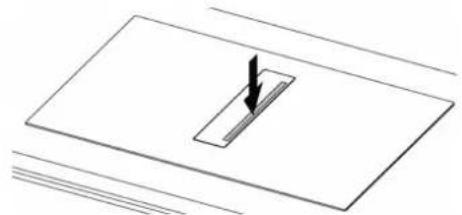
To open the glass flap, simply press anywhere on the outside of the flap itself (Fig. 31).
Fig. 31
natural_image
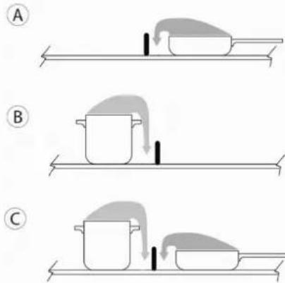
Pure technical diagram showing a rectangular component with a downward arrow, no text or symbols presentFor better smoke extraction, try to draw the smoke out of the part closest to the intake (Fig. 32).
Fig. 32
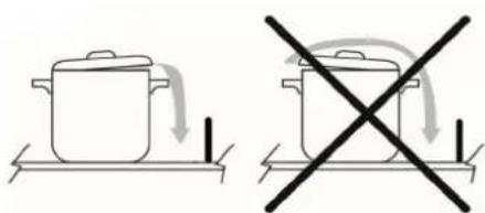
Do not place any objects on top of the glass flap or the control panel ("TC" Touch Control) (Fig.33).
Fig. 33
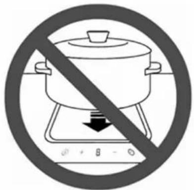

natural_image
Simple line drawing of a cooking pot with crossed lines indicating crossed pan, placed on a flat surface (no text or symbols)
natural_image
Simple line drawing of a cooking pot on a rectangular board with two crossed lines indicating resistance (no text or symbols)Switching on the extractor system:
- Open the central glass flap.
- Touch the Selection zone (12) to activate the extractor system.

CAUTION
The extraction area is equipped with a mechanical rotating central flap.
The flap must be opened before switching on the hood and activating the extraction system.
If the central flap is accidentally closed completely while extraction is activated, a sensor automatically stops the motor. Extraction only restarts when the flap is opened again.
Extraction speed (power):
The extractor is equipped with 9 extraction speed (power) levels. Touch and slide the display (12) with your fingers along the Selection bar (4) to increase or reduce:
→ to the right to increase the power level;
← to the left to decrease the power level.
The set power level will be displayed in the Selection/Display area (12)
Booster "P" function (Booster Extraction)
The extractor is equipped with an extra power level (Booster, in addition to level 9). The extractor will run at extra speed (Booster) for 5 minutes and then automatically switch to level 9.
To activate the Booster function, select the display (12) and slide your fingers along the Selection bar (4) past level 9 to "P".
Booster level 1 is indicated in the Selection/Display area (12) with the flashing symbol P.
Automatic function
When this function is activated, the hood will switch on at the most suitable speed, adapting the extraction capacity to the maximum cooking level used in the cooking zones.
When the cooking zones are switched off, the hood adapts its extraction speed, gradually decreasing it, eliminating residual odours and vapours.
Activation:
- Press the specific key (A) (14).
Deactivation:
- Press the specific key (A) (14) again.
If the hob is switched off with Automatic operation active, the fan will gradually switch off automatically.
After-run Fan function
This function should ensure that any residual odours and vapours are extracted. After the cooking process is completed and the hob is switched off, the fan continues to run.
There is a 5-minute automatic operation at level 1 which starts in the following cases:
- Manual shut-down of the hob (ON/OFF) with extractor fan
- Shut-down off the extractor fan in automatic mode via algorithm. When the function is active in the display (12) there is the dot (or 1. or A.) in the bottom right-hand corner and Ⓜ(11) flashes.
When automatic mode is active, the symbol R remains. In manual mode, level 1 is displayed.
In general, the fan speed can also be changed while the function is running and ends immediately if it is set to zero.
Extraction timer
An extraction timer can be set in the same way as for the cooking zone.
The timer is shown on the display (5). The timer only starts running when the cooking process is finished and no further cooking level is set.
The extraction timer can be activated in the following modes:
1. Manual mode 1
- Both the extraction level and the timer are set and all cooking zones are switched off. -> The hob remains switched on and the extraction level remains active for the timer time.
- Once the timer time has expired, the hob switches off completely.
2. Manual mode 2
- Both the extraction level and the timer are set and the hob is switched off via the ON/OFF button
- "After-run" function level 1 is set and remains active for the time set in the timer. -> At the end of the time set in the timer, the hob switches off completely.
3. Automatic mode
- The timer can be set as soon as extraction is running and starts operating as soon as all cooking zones are switched off.
- There is no timer warning after the after-run function has expired.
Filter cleaning warning
This indicator is normally off (13).
When the filters need to undergo maintenance, the symbol (13) lights up.

To reset, press the symbol Ⓥ (13) for 5 seconds and the symbol F or G appears on the display (12) indicating the need for maintenance of the grease filters F or the need for maintenance of the carbon ceramic G odour filters.
This function is programmed to warn that maintenance is required: Carbon ceramic odour filters: every 120 hours Grease filters: every 30 hours
The warning will also be signalled if the hood is not filtering: in this case proceed with normal cleaning of the grease filters and reset the warning. For maintenance/cleaning see the next chapter.

CAUTION
Before any maintenance or cleaning, disconnect the power supply from the hood (Fig. 1 – Fig. 2 WARNINGS chapter).
5.1 CLEANING THE EXTRACTOR INDUCTION HOB
Switch off the appliance before cleaning.
Do not clean the hob if the glass is too hot as there is a risk of scalding.
Remove light stains with a damp cloth with dishwashing liquid diluted in a little water. Then rinse with cold water and dry the surface thoroughly.
Highly corrosive or abrasive detergents and cleaning equipment that can cause scratches should absolutely be avoided.
Never use pressure or steam appliances.
Do not use objects that could scratch the ceramic glass.
Make sure that pots are dry and clean. Make sure there are no specks of dust or anything else on the ceramic hob or pots. Rough sliding pots will scratch the surface.
Spills of sugar, jam, jelly, etc. must be removed immediately. This will prevent damage to the surface.

CAUTION
The following products must NOT be used:
Products containing chlorides, especially those containing hydrochloric acid;
Halide based products;
Hydrogen peroxide based products;
Hypochlorous acid based bleaches;
Aggressive products containing acids;
Cleaners containing abrasive powder;
Silver cleaning products;
Detergents whose chemical composition is unknown;
Scouring pads, brushes or discs;
Rough cloths or rough paper;
Tools that have previously cleaned other metals or alloys.
Routine cleaning
Do not allow dirt to accumulate on the outer and inner surfaces of the hood.
Follow the same instructions for the central glass flap as for cleaning the induction hob.

CAUTION
The flap cannot be washed in a dishwasher.
Routine cleaning must be carried out before an excessive build-up of dirt can cause abrasion.
Before washing, it is necessary to remove any dust particles by blowing or vacuuming them, in order to avoid rubbing on the surface.
Where water has been used for cleaning or rinsing, especially in areas with a considerable presence of limescale, it is advisable to
dry the surface to prevent the appearance of stains.
To avoid contamination by iron particles, make sure that the tools chosen for cleaning have not previously been used on other metals or alloys.
Materials for cleaning stainless steel articles must be reserved exclusively for this purpose.
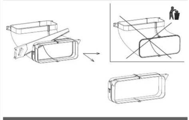
Particular care must be paid to the grease filter, which has the function of retaining the grease particles contained in the vapours, and to the tray below, which has the function of collecting the grease that could drip from the grease filter. Collect the condensate or collect the liquids accidentally poured into it through the glass flap.
Both of these elements must be washed with hot water and detergent (also in a dishwasher) when the corresponding warning appears or at least once a month.
The filter may become discoloured after a few washes. This is normal and does not mean that it has lost its effectiveness.
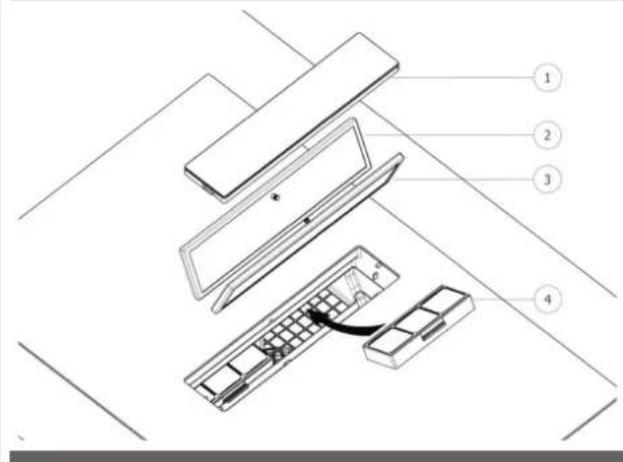
To service the metal grease filter and the tray underneath, it is essential to remove them from the hood.
To remove the metal grease filter and tray, proceed as shown in Fig. 34: -> Push down the right side of the central glass flap.
- Remove the central glass flap (1).
- Grasp the metal filters by the knob and pull them off (2).
- Remove the condensate drip tray (3)
Fig. 34
After doing these steps, you can clean all the components you have just removed. After cleaning, the components must be dried and finally replaced by performing the above steps (Fig. 31) in reverse order.
The ceramic odour filter, if present, has the function of retaining unpleasant cooking odours and must be regenerated when the
corresponding warning appears.
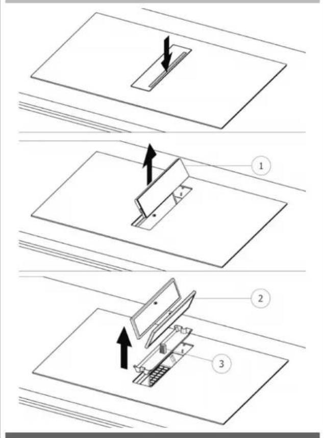
To regenerate ceramic odour filters, they must be removed from the hood.
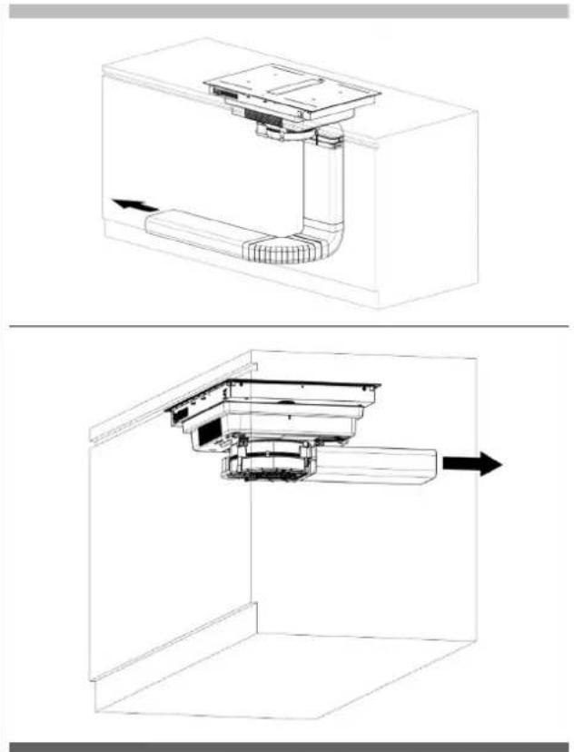
To remove the ceramic odour filters, proceed as shown in Fig. 35:
-> Push down the right side of the central glass flap.
-> Remove the central glass flap (1).
-> Grasp the metal filters by the knob and pull them both off (2.3).
-> Grasp the ceramic odour filters on their outer handles and pull them off (4).
Fig. 35
To thermally regenerate the ceramic odour filters, they must be placed in a preheated oven at 200°C for 45 minutes. Proper regeneration ensures constant filter effectiveness for 5 years.
Caution! Do not place the filters on the bottom of the oven but place them on a baking tray and place it at an intermediate height.
Contact the manufacturer to purchase a new filter.
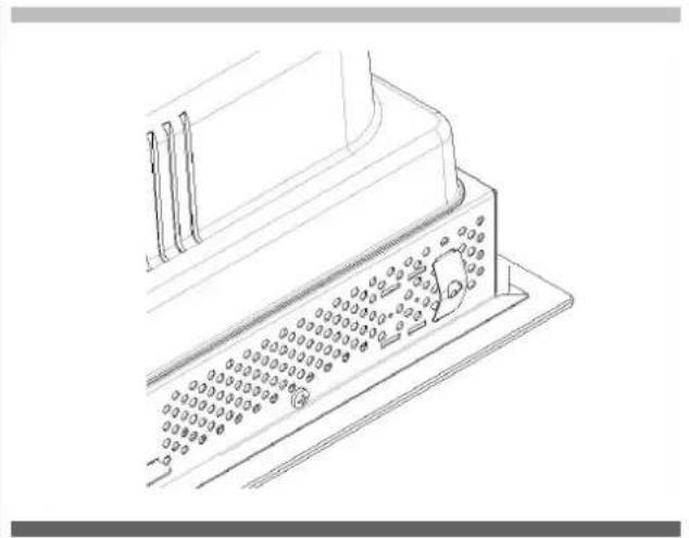
The hood is equipped with a safety cap for emptying any liquids that may have accidentally spilled into the condensation tray but which have exceeded its capacity. Check daily that there are no liquids inside the external hob tray. To do this, you need to remove the cap present under the hob, taking care to first place a container under and in correspondence with the cap itself to collect any liquids present (see Fig. 36).
Fig. 36
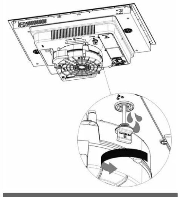
natural_image
Technical diagram of a refrigerator interior showing fan, ventilation duct, and air vent (no text or labels)
CAUTION
During the warranty period, repairs may only be carried out by the authorised Customer Service department.

CAUTION
Before any maintenance or cleaning, disconnect the power supply from the hood (Fig.1–Fig. 2 WARNINGS chapter).
- Unauthorised interventions and repairs may result in electrocution or short-circuiting, so please do not perform them. Leave this work to authorised technicians.
- In the case of minor faults, you can try to solve the problem by following the advice in the operating instructions.
- Rectification of faults or claims caused by incorrect use or installation of the device will not be covered under warranty. Costs for repairs will be borne by the user.
6.1.A MOTOR SAFETY
Following repeated opening and closing of the central flap, the electronics may temporarily block motor operation for safety reasons. This block lasts 5 minutes. At the end of the block, extraction will resume if the flap is still open and a valid extraction level is still set on the touch control.
6.2 CUSTOMER SERVICE
Before contacting the Customer Service Department, it is important to:
- Check whether the problem can be solved by consulting the error table under "Errors/Fault Finding".
- Switch the appliance off and on again (ON/OFF) to ensure that the problem has been resolved.
Finally, call Customer Service if error messages persist after the above checks have been made.
6.1 ERRORS / FAULT FINDING
The hob is programmed to provide corresponding error codes for quick and efficient troubleshooting.
The cooking zone displays show the error codes.
An error code always starts with the letters "E" or "ER" depending on the electronic component that generated the error.
| Possible Error Code | Error meaning Hob behaviour Possible cause Solution to Problem | |||
| ER03 | Continuous key activation detected | Shut-down after 10 seconds W | Water or pots positioned on TC* | Remove water or pots from TC* |
| ER20 | Internal TC* error Shut-down - Replace TC* | |||
| ER21 | Overheating Shut-down The temperature sensor | on TC* has detected a temperature >85 °C. | Let the hob cool down (the error disappears if the temperature is <75°C). Check that there are air outlets in the kitchen cabinet recess. | |
| ER22 | Internal TC* error Shut-down after 3.5 - 7.5 seconds | Replace TC* | ||
| ER31 | The internal configurations of the TC* and induction are inconsistent. | ER31 is displayed continuously. | The internal configuration data of the induction generator is different from the configuration inside the TC*. | Download the configuration. If the error is still present, replace the TC*. If the error is still present, replace the induction generator. |
| ER35 | Internal TC* error Shut-down - Replace TC* | |||
| ER36 | Internal TC* error Shut-down - Replace TC* | |||
| ER42 | Unsuitable secondary power supply | 12V or 5V too high / too low | ||
| ER47 | No communication to at least one paired LIN | ER47 is displayed continuously. | LIN cable damaged. No supply voltage for paired LIN. Defective paired LIN. | Check and replace LIN wiring. Check supply voltage. Replace paired LIN. |
(*) TC = Touch Control (Control panel)
| Possible Error Code | Error meaning Hob behaviour Possible cause Solution to Problem | |||
| E2 Overheating of the cooking zone temperature sensor | The corresponding cooking zone is switched OFF | Empty pots Do not heat empty | pots | |
| Wrong pots Use appropriate pots | ||||
| Pot or glass temperature too high Electronics temperature too high | Cooling system | |||
| E3 Wrong pot The corresponding cooking zone | or zones are switched OFF | The pots are losing their magnetic properties | Use appropriate pots | |
| Internal error in the generator circuit | Replace the generator | |||
| The pot creates an abnormal operating point on the module which can damage devices, e.g. the IGBT. | 1. The error is automatically cleared after 8s and the cooking zone can be used again. In case of subsequent errors, the pots must be replaced.2. Replace the generator if the error occurs without a pot on the cooking zone. | |||
| E4 Configuration error The cooking zone cannot be switched ON | The induction module is not yet configured | Perform manual configuration (see Touch Control documentation for details) | ||
| Induction module configuration data error | Delete and reconfigure the cooking zone. If the steps listed are unsuccessful, replace the module | |||
| EA. Internal error Cooking zones are switched OFF | Interference or abnormal signal | detected (e.g. EMC noise, condensate on PCB) | 1. Switch off the hob, remove all pots and allow the hob to cool down2. If the error persists:Replace the generator | |
| Hardware defect (e.g. wrong flash or MCU, defective inductor) | 1. Switch off the hob, remove all pots and allow the hob to cool down2. If the error persists:Replace the generator3. If the inductor is defective:Replace the inductor | |||
| EH Temperature sensor blocked for the cooking zone | The corresponding cooking zone is switched OFF | Insufficient temperature variation after switching on the hob | Cool the glass | |
| E5 | No communication between the user interface and the induction generator Generator | The cooking zone cannot be SWITCHED ON | Defective LIN wiring or power supply wiring (e.g. line conductor missing) | Check wiring and supply voltage |
| No mains voltage on the slave board | Check mains voltage connection on the slave board | |||
| Internal error in the generator or filter circuit | Replace the generator | |||
| (Mixed version) HiLight relay voltage error - Faulty hardware device | Replace the generator | |||
| Data configuration error Delete and reconfigure the cooking zone. | ||||
Notes: If no error code is displayed and the user interface does not react to key presses, check the supply voltage for missing line conductors, missing jumpers or incorrect 400 V connections.
7.1 DECOMMISSIONING
Decommissioning means the definitive shut-down and disassembly of the appliance. Following decommissioning, the appliance can be incorporated into another piece of furniture, resold privately or disposed of.

CAUTION
For decommissioning, the appliance must be switched off and the power supply must be disconnected from the hood (Fig. 1-2 WARNINGS chapter).

CAUTION
The disconnection and closing of electrical lines must only be carried out by specialised personnel.
7.2 DISASSEMBLY
Disassembly requires that the appliance be accessible for disassembly and has been disconnected from the power supply.
To carry out this operation you must:
Loosen screws and fixing brackets
Remove any silicone seals
Disconnect the motor and the extraction duct from the hob
Remove the hob from above
7.3 ENVIRONMENTAL PRESERVATION
Packaging materials are environmentally friendly and recyclable.
Electronic devices are made of recyclable materials that are sometimes harmful to the environment but are necessary for the proper functioning and safety of the appliance.
7.4 DISPOSAL
This appliance is marked in accordance with the European Directive 2012/19/EC, Waste Electrical and Electronic Equipment (WEEE). The symbol on the product or on the packaging indicates that the product should not be treated as normal household waste but should be taken to the appropriate collection point for the recycling of electrical and electronic equipment.
By disposing of this product appropriately, you will help prevent potential negative consequences for the environment and your health. For more detailed information about recycling of this product, please contact your local city office, your household waste disposal service or the shop where you purchased the product.

INDEX PAGE
1 - GÉNÉRALITÉS 2
2 - AVERTISSEMENTS 3
3 - INSTALLATION 6
3.1 TRAITEMENT DE L'AIR 6
3.2 INDICATIONS PRÉLIMINAIRES 6
3.3 INSTALLATION 8
3.3.A INSTALLATION DE LA TABLE À INDUCTION 8
3.3.B INDICATIONS DE CONSTRUCTION
- SYSTÈME EXTRACTION D'AIR SUR PLINTHE 10
3.3.C INDICATIONS DE CONSTRUCTION
- SYSTÈME EXTRACTION D'AIR ARRIÈRE 11
3.3.D ASSEMBLAGE TUYAU EXTRACTION
D'AIR 11
3.4 RACCORDEMENT ÉLECTRIQUE 12
4 - FONCTIONNEMENT 14
4.1 DESCRIPTION DE LA TABLE À INDUCTION AVEC HOTTE ASPIRANTE 14
4.1.A CARACTÉRISTIQUES TECHNIQUES 14
4.1.B CARACTÉRISTIQUES PRINCIPALES
DE COMMANDE DE LA TABLE À
INDUCTION AVEC HOTTE ASPIRANTE 15
4.2 RÉCIPIENTS POUR LA CUISSON 15
4.2.A QUALITÉ DES CASSEROLES 15
4.2.B DIMENSIONS DES CASSEROLES 15
4.3 TABLE DE CUISSON À INDUCTION 16
4.3.A INDICATEUR FOYER 16
4.3.B CARACTÉRISTIQUES DE LA TABLE DE CUISSON 16
4.3.C CONFIGURATION DE LA TABLE DE CUISSON 16
4.3.D FONCTIONNEMENT DE LA TABLE
DE CUISSON 20
4.4 ASPIRATION 23
4.4.A INDICATIONS PRÉLIMINAIRES 23
4.4.B FONCTIONNEMENT ASPIRATION 24
INDEX PAGE
5 - ENTRETIEN ET NETTOYAGE 26
5.1 NETTOYAGE DE LA TABLE À INDUCTION AVEC HOTTE ASPIRANTE 26
GUIDE POUR LA RÉSOLUTION DES
6 - PROBLÈMES 28
6.1 ERREURS / RECHERCHE DES PANNES 28
6.1.A SÉCURITÉ MOTEUR 28
6.2 SERVICE ASSISTANCE 28
7 - MISE HORS SERVICE 30
7.1 MISE HORS SERVICE 30
7.2 DÉMONTAGE 30
7.3 PROTECTION DE L'ENVIRONNEMENT 30
7.4 ÉLIMINATION 30
natural_image
Illustration of an electrical circuit breaker with a hand giving a thumbs-up gesture (no text or symbols)Fig. 2

natural_image
Line drawing of a table with crossed cutlery and four kitchen utensils (sporks, fork, knife) arranged on a surface (no text or symbols)natural_image
Technical line drawing of a mechanical assembly inside a 3D enclosure, showing internal components and directional arrows (no text or symbols)natural_image
Technical line drawing of a mechanical assembly or enclosure with internal components (no text or symbols)3.2 INDICATIONS PRÉLIMINAIRES
natural_image
Collection of various hand tools and equipment including a hard hat, saw, screwdriver, and rubber can (no text or symbols visible)natural_image
Simple line drawing of a cabinet with doors and a horizontal bar, no text or symbols presentFig 7

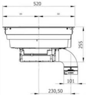
Fig 8C
C

natural_image
Pure architectural floor plan lines without any text, numbers, or symbolsFig 8D
D

natural_image
Pure architectural floor plan lines without any text, numbers, or symbolsnatural_image
Technical line drawing of a mechanical component with mounting base and internal channels (no text or symbols)natural_image
Technical diagram of a mechanical component with an arrow indicating motion, labeled Fig. 16 (no text or symbols on the diagram itself)

natural_image
Technical line drawing of a mechanical component with cross-sectional views and a person silhouette (no text or symbols)3.3.C INDICATIONS DE CONSTRUCTION - SYSTÈME EXTRACTION D'AIR ARRIÈRE
natural_image
Technical line drawing of a mechanical component with cross-sectional views and a person silhouette (no text or symbols)3.3.D ASSEMBLAGE TUYAU EXTRACTION D'AIR
natural_image
Technical line drawings of various electronic components or connectors, including rectangular blocks and a fan-like structure (no text or symbols)3.4 RACCORDEMENT ÉLECTRIQUE
natural_image
Line drawing of an electrical fuse box (no text or symbols)1x32 circuit breaker
220×240V
1+N+GDN

BI-PHASE
min. 4 × 1.5 mm^2
2x16 circuit breaker
380×415V
3+N+GDN

THREE-PHASE
min. 5×1.5 mm²
3x16 circuit breaker
380×415V
3+N+GDN

MONO-PHASE
3×4 mm ^2
1x32 circuit breaker
220×240V
1+N+GDN

TYPE DE CÂBLES :
H05VV-F
H05V2V2-F
H05RN-F
H05RR-F
(OU CATÉGORIES SUPÉRIEURES)
Couleur Connexion
| MONOFASE 3x4 mm ^2 | MONOFASE 5x1.5 mm ^2 | BIFASE 4x1.5 mm ^2 | TRIFASE 5x1.5 mm ^2 | |
| NOIR L L1 L1 | ||||
| MARRON L L L3 L3 | ||||
| BLEU (GRIS) N N L2 | ||||
| BLEU N N N N | ||||
| JAUNE/VERT MISE À LA TERRE | ||||
| CAVALIER | ||||
4.1 DESCRIPTION DE LA TABLE À INDUCTION AVEC HOTTE ASPIRANTE
| Dimensions foyers OCTA 210 x 190 mm |
| Niveau min-max (booster) power foyers 700W-2100W (3000W) |
natural_image
Three identical 3D-rendered kitchen utensils with no visible text or symbols, each enclosed in a circular frame (no text or symbols present)4.2.B DIMENSIONS DES CASSEROLES
natural_image
Pure diagram of a rectangular object with a downward arrow inside, no text or symbols present
natural_image
Simple line drawing of a cooking pot with crossed lines indicating crossed pan, placed on a flat surface (no text or symbols)
natural_image
Simple line drawing of a pot on a heating table with two crossed lines indicating resistance (no text or symbols)4.4.B FONCTIONNEMENT ASPIRATION
natural_image
Technical diagram of a refrigerator interior showing fan, vent, and water drop system (no text or labels)
ATTENTION
natural_image
Illustration of an electrical circuit breaker with a hand gesture indicating power input (no text or symbols present)Abb. 2
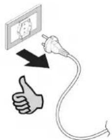
natural_image
Illustration of kitchen utensils including fork, knife, screwdriver, and plate (no text or symbols)natural_image
Technical line drawing of a mechanical assembly inside a 3D enclosure, showing internal components and directional arrows (no text or symbols)natural_image
Technical line drawing of a mechanical or electrical component assembly (no text or symbols visible)3.2 VORLÄUFIGE ANGABEN
natural_image
Collection of mechanical and industrial tools including hard hats, screwdrivers, and spray canes (no text or symbols)natural_image
Simple line drawing of a cabinet with doors and a horizontal bar, no text or symbols presentAbb 7


Abb 8C
C

natural_image
Pure architectural floor plan lines without any text, numbers, or symbolsAbb 8D
D

natural_image
Pure architectural floor plan lines without any text, numbers, or symbolsnatural_image
Technical line drawing of a mechanical component with mounting base and internal channels (no text or symbols)Montage - Installation:
natural_image
Technical line drawing of a mechanical device with an inset close-up showing internal components (no text or symbols)natural_image
Technical diagram of a mechanical device with a curved component and directional arrow (no text or symbols)

natural_image
Technical line drawing of a mechanical component with cross-sectional views and a person silhouette (no text or symbols)Abb. 20.1

natural_image
Technical line drawing of a mechanical component with cross-sectional views and a person in a trash bin (no text or symbols)natural_image
Technical line drawings of rectangular and cylindrical components with internal structures, no text or symbols presentnatural_image
Line drawing of an electrical fuse box (no text or symbols)1x32 circuit breaker
220×240V
1+N+GDN

DOPPELPHASIG
min. 4×1.5 mm ^2
2x16 circuit breaker
380×415V
3+N+GDN
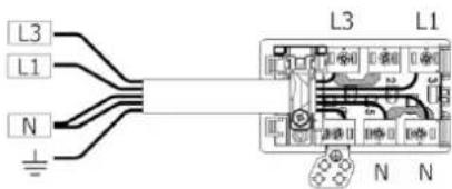
DREIPHASIG
min. 5×1.5 mm²
3x16 circuit breaker
380×415V
3+N+GDN
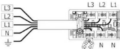
EINPHASIG
3×4 mm²
1x32 circuit breaker
220×240V
1+N+GDN
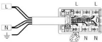
KABELTYP:
H05VV-F
H05V2V2-F
H05RN-F
H05RR-F
natural_image
Three identical 3D-rendered kitchen utensils with no visible text or symbols, each with a small emoji below (no text or symbols on the utensils)natural_image
Simple line drawing of a boat on a platform with a small object inside, no text or symbols present.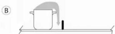
natural_image
Simple line drawing of a pot with a downward arrow and a black object on a horizontal surface (no text or symbols)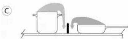
natural_image
Illustration of a cooking process with a pot and lid on a tray, no text or symbols presentnatural_image
Pure technical diagram showing a rectangular component with a downward arrow, no text or symbols present
natural_image
Simple line drawing of a cooking pot with a crossed X mark on a flat surface, no text or symbols present.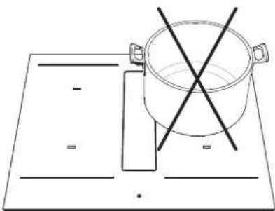
natural_image
Simple line drawing of a cooking pot on a rectangular board with two crossed lines indicating resistance (no text or symbols)4.4.B ABSAUGVORGANG
natural_image
Pure diagram of a rectangular object with a downward arrow inside, no text or symbols present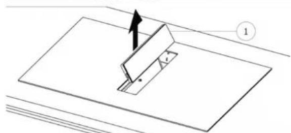
natural_image
Diagram of a mechanical assembly with a bracket and mounting plate, showing an arrow indicating direction (no text or symbols)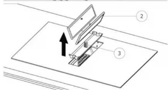
natural_image
Technical diagram of a refrigerator interior showing fan, vent, and water drop system (no text or labels)
ACHTUNG
natural_image
Illustration of an electrical circuit breaker with a hand giving a thumbs-up gesture (no text or symbols)Fig. 2
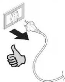
natural_image
Line drawing of a table with crossed cutlery and four kitchen utensils (sporks, fork, knife) arranged on a surface (no text or symbols)natural_image
Technical line drawing of a mechanical assembly inside a 3D enclosure, showing internal components and directional arrows (no text or symbols)natural_image
Technical line drawing of a mechanical assembly or housing component (no text or symbols visible)3.2 INDICACIONES PRELIMINARES
natural_image
Collection of construction tools including hard hat, saw, screwdriver, and rubber can tool (no text or labels)natural_image
Simple line drawing of a cabinet with doors and a horizontal bar, no text or symbols presentFig 7


Fig 8C
C
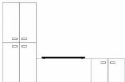
natural_image
Pure architectural floor plan lines without any text, numbers, or symbolsFig 8D
D
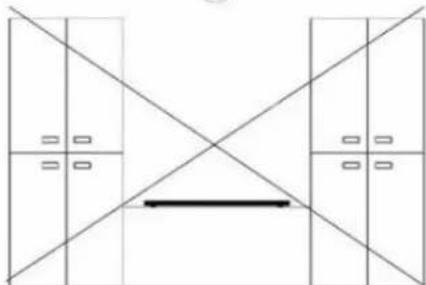
natural_image
Pure architectural floor plan lines without any text, numbers, or symbolsnatural_image
Technical line drawing of a mechanical component with mounting base and internal channels (no text or symbols)natural_image
Technical line drawing of a mechanical device with an inset close-up showing internal components (no text or symbols)Apoyar la placa (Fig. 16)
Fig. 16
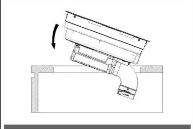
natural_image
Technical diagram of a mechanical assembly with a curved component and directional arrow (no text or symbols)
Fig. 18 Placa de 80cm.
(7 tomas de aire)
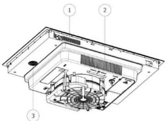

natural_image
Technical line drawing of a mechanical component with cross-sectional views and a person silhouette (no text or symbols)Fig. 20.1

natural_image
Technical line drawing of a mechanical component with cross-sectional views and a person in a trash bin (no text or symbols)3.3.C INDICACIONES CONSTRUCTIVAS - DESCARGA TRASERA
natural_image
Technical line drawings of various electronic components or connectors, including rectangular blocks and a grid-like structure (no text or symbols)natural_image
Line drawing of an electrical fuse box (no text or symbols)1x32 circuit breaker
220×240V
1+N+GDN
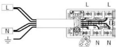
BI-PHASE
min. 4×1.5 mm²
2x16 circuit breaker
380×415V
3+N+GDN
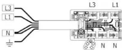
THREE-PHASE
min. 5×1.5 mm²
3x16 circuit breaker
380×415V
3+N+GDN
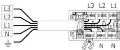
MONO-PHASE
3×4 mm ^2
1x32 circuit breaker
220×240V
1+N+GDN

TIPO DE CABLES:
H05VV-F
H05V2V2-F
H05RN-F
H05RR-F
(O CATEGORÍAS SUPERIORES)
Color Conexión
| MONOFÁSICA 3x4 mm ^2 | MONOFÁSICA 5x1.5 mm ^2 | BIFÁSICA 4x1.5 mm ^2 | TRIFÁSICA 5x1.5 mm ^2 | |
| NEGRO L L1 L1 | ||||
| MARRÓN L L L3 L3 | ||||
| AZUL (GRIS) N N L2 | ||||
| AZUL N N N N | ||||
| AMARILLO/VERDE | PUESTA A TIERRA | |||
| PUENTE | ||||
natural_image
Three 3D-rendered kitchen utensils with no visible text or symbols, including a frying pan and a square with two small smiley faces (no text or symbols)4.2.B DIMENSIONES DE LAS OLLAS
natural_image
Pure diagram of a rectangular object with a downward arrow inside, no text or symbols present
natural_image
Simple line drawing of a cooking pot with crossed lines indicating crossed pan, placed on a flat surface (no text or symbols)
natural_image
Simple line drawing of a cooking pot on a rectangular board with two crossed lines indicating resistance (no text or symbols)natural_image
Pure diagram of a rectangular plate with a downward arrow indicating direction, no text or symbols present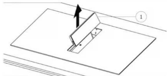
natural_image
Technical diagram showing a mechanical assembly with a bracket and mounting plate, no text or symbols present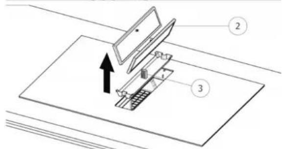
natural_image
Technical diagram of a refrigerator interior showing fan, vent, and cooling unit (no text or labels)
ATENCIÓN
(*) TC = Touch Control (Panel de control)
natural_image
Illustration of an electrical circuit breaker with a hand giving a thumbs-up gesture (no text or symbols)Fig. 2

natural_image
Illustration of kitchen utensils including fork, knife, screwdriver, and plate (no text or symbols)natural_image
Technical line drawing of a mechanical assembly inside a 3D enclosure, showing internal components and directional arrows (no text or symbols)natural_image
Technical line drawing of a mechanical assembly or housing component (no text or symbols visible)3.2 OBSERVAÇÕES PRELIMINARES
natural_image
Collection of various hand tools and accessories including a hard hat, saw, and rubber can (no text or symbols visible)natural_image
Simple line drawing of a cabinet with doors and a horizontal bar, no text or symbols presentFig 7


Fig. 8C
C
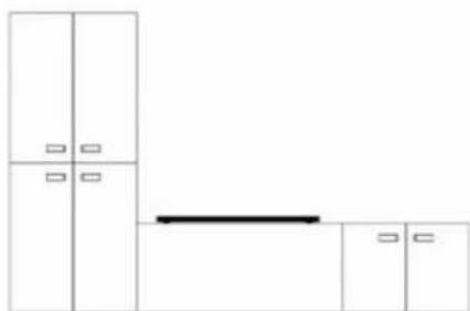
natural_image
Pure architectural floor plan lines without any text, numbers, or symbolsFig. 8D
D

natural_image
Pure architectural floor plan lines without any text, numbers, or symbolsnatural_image
Technical line drawing of a mechanical component with mounting base and internal channels (no text or symbols)natural_image
Technical line drawing of a mechanical device with an inset close-up showing internal components (no text or symbols)Apoiar a placa (Fig. 16)
Fig. 16

natural_image
Technical diagram of a mechanical assembly with a curved component and directional arrow (no text or symbols)
Fig. 18 Placa de 80 cm.
(7 entradas de ar)


natural_image
Technical line drawing of a mechanical component with cross-sectional views and a person silhouette (no text or symbols)Fig. 20.1

natural_image
Technical line drawing of a mechanical component with cross-sectional views and a person in a trash bin (no text or symbols)natural_image
Technical line drawings of various electronic components or connectors, including rectangular blocks and a grid-like structure (no text or symbols)natural_image
Line drawing of an electrical fuse box (no text or symbols)BIFÁSICO
min. 4 × 1.5 mm^2
2x16 disjuntor
380×415V
3+N+GDN

TRIFÁSICO
min. 5×1.5 mm²
3x16 disjuntor
380×415V
3+N+GDN

MONOFÁSICO
3×4 mm²
1x32 disjuntor
220×240V
1+N+GDN
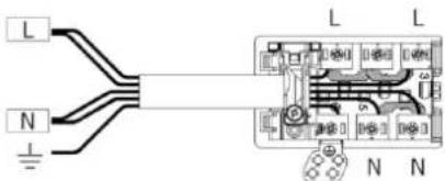
TIPO DE CABOS:
H05VV-F
H05V2V2-F
H05RN-F
H05RR-F
(OU CATEGORIAS SUPERIORES)
Cor Conexão
| MONOFÁSICA 3x4 mm ^2 | MONOFÁSICA 5x1.5 mm ^2 | BIFÁSICA 4x1.5 mm ^2 | TRIFÁSICA 5x1,5 mm ^2 | |
| PRETO L L1 L1 | ||||
| MARROM L L L3 L3 | ||||
| AZUL (CINZA) N N L2 | ||||
| AZUL N N N N | ||||
| AMARELO/VERDE | INSTALAÇÃO DE TERRA | |||
| PONTE | ||||
natural_image
Illustration of three frying pan designs with no text or symbols, showing different shapes and expressions (no text or symbols present)4.2.B DIMENSÕES DAS PANELAS
natural_image
Pure technical diagram showing a rectangular component with a downward arrow, no text or symbols present
natural_image
Simple line drawing of a cooking pot on a stove with a crossed-out pan (no text or symbols)
natural_image
Simple line drawing of a cooking pot on a rectangular board with two crossed lines indicating resistance (no text or symbols)natural_image
Pure diagram of a rectangular object with a downward arrow inside, no text or symbols present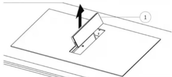
natural_image
Technical diagram of a mechanical assembly with a cutting tool and base plate (no text or symbols)
natural_image
Technical diagram of a refrigerator interior showing fan, vent, and cooling unit (no text or labels)