IT 105 - Measuring equipment BENNING - Free user manual and instructions
Find the device manual for free IT 105 BENNING in PDF.
User questions about IT 105 BENNING
0 question about this device. Answer the ones you know or ask your own.
Ask a new question about this device
Download the instructions for your Measuring equipment in PDF format for free! Find your manual IT 105 - BENNING and take your electronic device back in hand. On this page are published all the documents necessary for the use of your device. IT 105 by BENNING.
USER MANUAL IT 105 BENNING
Installation Tester BENNING IT 105 (index level .01)

Notice d'emploi
Installation Tester BENNING IT 105 (index level .01)
Figure 1a: Front tester panel/ device top
Figure 1b: Function selector switch
Figure 3: Measurement of voltage via 4 mm measuring leads
Figure 4: Measurement of voltage, RCD and Zs (Zloop)/Z1 (Zline) via test cable with shock-proof plug
Figure 5: Measurement of voltage, RCD and Z_S (Zloop)/ Z_I (Zline) via of 4 mm measuring leads
Figure 6: Z I measurement and PSC measurement (phase-phase)
Figure 7: Rotary field (phase sequence)
Figure 8: Battery/fuse replacement
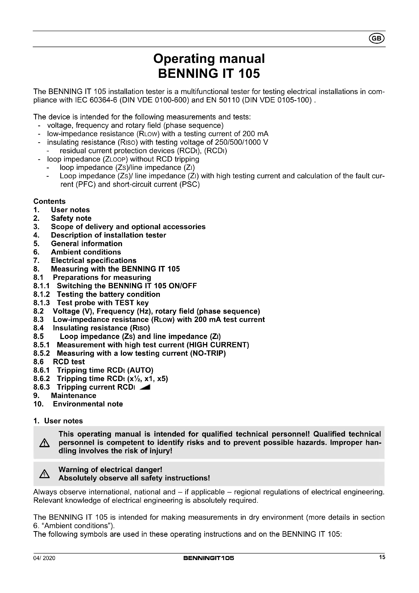
Operating manual BENNING IT 105
The BENNING IT 105 installation tester is a multifunctional tester for testing electrical installations in compliance with IEC 60364-6 (DIN VDE 0100-600) and EN 50110 (DIN VDE 0105-100).
The device is intended for the following measurements and tests:
- voltage, frequency and rotary field (phase sequence)
- low-impedance resistance (RLOW) with a testing current of 200 mA
- insulating resistance (Riso) with testing voltage of 250/500/1000 V
- residual current protection devices (RCDt), (RCDl)
- loop impedance (ZLOOP) without RCD tripping
- loop impedance (Zs)/line impedance (Zl)
- Loop impedance (Zs)/ line impedance (Zl) with high testing current and calculation of the fault current (PFC) and short-circuit current (PSC)
Contents
- User notes
- Safety note
- Scope of delivery and optional accessories
- Description of installation tester
- General information
- Ambient conditions
- Electrical specifications
- Measuring with the BENNING IT 105
8.1 Preparations for measuring
8.1.1 Switching the BENNING IT 105 ON/OFF
8.1.2 Testing the battery condition
8.1.3 Test probe with TEST key
8.2 Voltage (V), Frequency (Hz), rotary field (phase sequence)
8.3 Low-impedance resistance (RLOW) with 200 mA test current
8.4 Insulating resistance (Riso)
8.5 Loop impedance (Zs) and line impedance (Zl)
8.5.1 Measurement with high test current (HIGH CURRENT)
8.5.2 Measuring with a low testing current (NO-TRIP)
8.6 RCD test
8.6.1 Tripping time RCDt (AUTO)
8.6.2 Tripping time RCDt (x ^1/2 , x1, x5)
8.6.3 Tripping current RCDI - Maintenance
- Environmental note
1. User notes

This operating manual is intended for qualified technical personnel! Qualified technical personnel is competent to identify risks and to prevent possible hazards. Improper handling involves the risk of injury!

Warning of electrical danger! Absolutely observe all safety instructions!
Always observe international, national and – if applicable – regional regulations of electrical engineering. Relevant knowledge of electrical engineering is absolutely required.
The BENNING IT 105 is intended for making measurements in dry environment (more details in section 6. "Ambient conditions").
The following symbols are used in these operating instructions and on the BENNING IT 105:

Warning of electrical danger!
Indicates instructions which must be followed to avoid danger to persons.

Important, comply with the documentation!
This symbol indicates that the stipulations in the operating instructions must be followed in order to avoid danger.
Do not use the tester in distribution systems with voltages higher than 440 V.

The tester is overheated. The “Hot” symbol is shown on the digital display ② and measurements are interrupted until the internal temperature has dropped below the admissible limiting value. Disconnect the tester from the test object and switch off the tester.

This symbol on the BENNING IT 105 means that the BENNING IT 105 complies with the EU directives.

This symbol appears on the display to indicate a discharged battery. As soon as the battery symbol flashes, immediately replace the batteries by new ones.

This symbol appears on the display to indicate a defective fuse (see section 9.4 "Fuse replacement").

(DC) Direct voltage or current

(AC) Alternating voltage or current

Earth (voltage to ground)

Protection class II
2. Safety note
The instrument is built and tested in accordance with
EN 61010-1 (VDE 0411 part 1)
EN 61010-2-030 (VDE 0411 part 2-030), EN 61010-031 (VDE 0411 part 031)
EN 61557-1, -2, -3, -4, -6, -7 and 10 (VDE 0413 part 1, 2, 3, 4, 6, 7 and 10)
and has left the factory in perfectly safe technical condition. To maintain this condition and to ensure safe operation of the installation tester, the user must observe the notes and warnings given in these instructions at all times. Improper handling and non-observance of the warnings might involve severe injuries or danger to life.

WARNING! Be extremely careful when working with bare conductors or main line carrier! Contact with live conductors will cause an electric shock!
Remember that work on electrical components of all kinds is dangerous. Even low voltages of 30 V AC and 60 V DC may be dangerous to human life.

The unit may be used only in power circuits within overvoltage category III with a conductor for 300 V against ground.
Only use suitable measuring leads for this. With measurements within measurement category III, the projecting conductive part of a contact tip of the measuring leads must not be longer than 4 mm.
Prior to carrying out measurements within measurement category III, the push-on caps provided with the set and marked with CAT III must be pushed onto the contact tips. The purpose of this measure is user protection.

The protective conductor resistance measurement might be distorted by impedances connected in parallel of additional operating circuits and by transient currents.
| Measurements of the protective conductor resistance and of the insulating resistance must be carried out at idle system parts only.Do not touch the measuring probes!During insulating resistance measurements, high electric currents might be applied to the measuring probes. | |
| Do not touch any metal parts of the test object during measurement. | |
| Disconnect the BENNING IT 105 from the electrical system directly after the test is finished. | |
| Only use the measuring leads included in the scope of delivery of the BENNING IT 105. | |
| Use the BENNING IT 105 only in compliance with the intended use specified in this documentation. Non-observance might impair the protective function of the BENNING IT 105. | |
| Before starting the installation tester, always check it as well as all measuring leads and wires for signs of damage. |
Should it appear that safe operation of the installation tester is no longer possible, it should be shut down immediately and secured to prevent that it is switched on accidentally.
It must be assumed that safe operation is no longer possible
- if the instrument or the measuring leads show visible signs of damage, or
- if the installation tester no longer works, or
- after long periods of storage under unfavourable conditions, or
- after being subject to rough transportation, or
- if the device is exposed to moisture.
| Maintenance:Do not open the tester, because it contains no components which can be repaired by the user. Repair and service must be carried out by qualified personnel only! (Exception: see section 9.4 “Fuse replacement”) |
| Cleaning:Regularly wipe the housing by means of a dry cloth and cleaning agent. Do not use any polishing agents or solvents! |
3. Scope of delivery and optional accessories
The scope of delivery for the BENNING IT 105 with index level .01 comprises:
3.1 one installation tester BENNING IT 105 (measuring lead sockets: black, blue, green) (10220312)
3.2 one transport case with accessory compartment (10198412)
3.3 one probe tip with TEST key (10162173)
3.4 one test cable with shock-proof plug (black, blue, green) (10220313)
3.5 one set of measuring leads/ alligator clips (black, blue, green) (10217751)
3.6 one 4 mm adapter (blue) (10217754)
3.7 one carrying strap (10198409)
3.8 six mignon batteries 1.5 V (IEC LR6/ type AA) and one fuse
3.9 one operating manual
3.10 one calibration certificate
Note:
The index level .01 includes a color adjustment of the measuring lead sockets of the tester and the measuring accessories.
Prior to index level .01, the following items were supplied with a different color code:
3.1 one installation tester BENNING IT 105 (measuring lead sockets: red, black, green) (10198414)
3.4 one test cable with shock-proof plug (red, black, green) (10198407)
3.5 one set of measuring leads/ alligator clips (red, black, green) (10199406)
3.6 was not part of the scope of the delivery
Parts subject to wear:
- The BENNING IT 105 contains a fuse as protection against overload: One fuse, nominal current rating 1.6 A, 1000 V, superfast-acting (FF), breaking capacity ≥ 30 D = 6.3 mm, L = 32 mm (part no. 10194027).
- The BENNING IT 105 is powered by six mignon batteries 1.5 V (IEC LR6/ type AA).
Note on optional accessories:
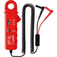
- BENNING TA 5 40 m measuring lead with rewinder and wrist strap, for measuring protective conductor connections (044039).
4. Description of the installation tester
See figure 1a: Front tester panel/ device top
See figure 1b: Function selector switch
See figure 1c: Digital display
The display and operator control elements specified in figure 1a, 1b and 1c are designated as follows:
① Function selector switch
② Digital display, dimensions 95 x 55 mm, with illumination
③ Function keys F1 to F4
④ TEST key
⑤ Black measuring lead jack L/L1
⑥ Green measuring lead jack PE/L2
⑦ Blue measuring lead jack N/L3
Function selector switch
Ⓐ Voltage (V), Frequency (Hz), rotary field
⑧ Insulation resistance (Riso) with 1000 V testing voltage
© Insulation resistance (Riso) with 500 V testing voltage
⑭ Insulation resistance (Riso) with 250 V testing voltage
⑤ Continuity test (RLow) with 200 mA testing current
⑤ OFF
© Loop/line impedance (Zs/Zi HIGH CURRENT) with high testing current and calculation of the short-circuit/fault current (PSC/PFC)
⑧ Loop/line impedance (Zs/Zi NO-TRIP) without tripping of RCDs (residual current protection devices) and calculation of the short-circuit/fault current (PSC/PFC)
① RCD tripping time (AUTO)
⑤ RCD tripping time with 12 x IΔN (RCDt)
© RCD tripping time with 1 x IΔN (RCDt)
⑤ RCD tripping time with 5 x IΔN (RCDt)
M RCD tripping current with ramp test (RCD1)
Digital display
Symbols of the function key F1. Repeatedly press the F1 key to select the options available in the selected test function.
Symbols of the function key F2. Repeatedly press the F2 key to select the options available in the selected test function.
Symbols of the function key F3. Repeatedly press the F3 key to select the options available in the selected test function.
Symbols of the function key F4. Repeatedly press the F4 key to select the options available in the selected test function.
Progress indicator of the loop impedance (Zs, NO-TRIP)
Symbols of the selected RCD test function
G RCD status. Provides information about RCD tripping.
H Phase sequence indicator
① Battery symbol, status of the remaining battery capacity
① Sub-display for measuring results
K Main display for measuring results
Mains voltage indicator. Confirms the correct voltage potentials between external conductor and earth (L-PE), external conductor and neutral conductor (L-N) as well as neutral conductor and earth (N-PE) for RCD measurement and loop/line impedance measurement.
Indication for correct mains voltage:

Note:
If the mains voltage indicator flashes, check the measuring leads for correct connection or turn the shock-proof plug of the test cable by 180^ :
- Connect the black measuring lead/jack L ⑤ to the external conductor L.
- Connect the blue measuring lead/jack N ⑦ to the neutral conductor N.
- Connect the green measuring lead/jack PE ⑥ to earth PE.
In case of an incorrect mains voltage, measurement will be blocked.
Warning symbols. "Warning of electrical danger!", "Attention! Please observe documentation!" and "Tester is overheated!"; please observe the relevant sections of this operating manual.
N Symbol indicating a defective fuse
5. General information
The BENNING IT 105 is intended for electrical safety tests in compliance with IEC 60364-6 (DIN VDE 0100-600) and EN 50110 (DIN VDE 0105-100).
- Appliance dimensions: (length x width x height) = 235 x 132 x 92 mm
- Appliance weight: 1370 g incl. batteries
6. Ambient conditions
- The BENNING IT 105 is intended for making measurements in dry environment,
- Maximum barometric elevation for making measurements: 2000 m,
- Overvoltage category/ setting category: IEC 61010-1 → 300 V category III,
- Contamination class: 2,
- Protection class: IP 40 (IEC/ EN 60529, DIN VDE 0470-1)
IP 40 means: Protection against access to dangerous parts and protection against solid impurities of a diameter > 1 mm, (4 - first index). No protection against water, (0 - second index).
- EMC: EN 61326-1
- Ambient temperature and relative humidity:
For ambient temperatures from 0 °C to 40 °C: non-condensing
- Storage temperature: The BENNING IT 105 can be stored at any temperature within the range of -25 °C to +65 °C (relative humidity from 0 to 90 %). The batteries should be removed from the instrument for storage.
7. Electrical specifications
Note: The measuring accuracy is specified as the sum of
- a relative fraction of the measured value and
- a number of digits (counting steps of the least significant digit).
The specified measuring accuracy is valid for temperatures within the range of 18 °C to 28 °C and for a relative humidity lower than 80 %.
7.1 Voltage (V) frequency (Hz)
| Measuring range | Resolution | Accuracy |
| 0 V - 440 V AC/DC | 1 V | ± (5 % + 2 digits) |
| 45 Hz - 65 Hz | 1 Hz | ± 1 Hz |
7.2 Continuity test (RLOW)
| Measuring range | Resolution | Accuracy |
| 0.15 Ω - 199 Ω | max. 0.01 Ω | ± (2 % + 5 digits) |
Measuring current: > 200 mA
Open-circuit voltage: >4 V, <8 VDC
Number of periodic testing (EN 61557-4): approx. 4000
7.3 Insulating resistance measuring (Riso)
Measuring range Resolution Accuracy
| 0.20 MΩ - 199 MΩ max. 0.01 MΩ ± (5 % + 5 digits) |
Test voltage: 250 VDC/ 500 VDC/ 1000 VDC, - 0 % + 20 %
Test current: > 1 mA, < 2 mA in case of a short-circuit
Number of periodic testing (EN 61557-2): approx. 3000
Test voltage indication: ± 5 %
7.4 Loop impedance (Zs)
Measuring range Resolution Accuracy
| high test current: | ||
| 0.20 Ω - 1999 Ω max. 0.01 Ω ± (5 % + 5 digits) | ||
| without RCD tripping: | ||
| 1.00 Ω - 1.99 Ω 0.01 Ω | ± (5 % + 12 digits) | |
| 2.0 Ω - 19.9 Ω | 0.1 Ω | ± (5 % + 12 digits) |
| 20 Ω - 1999 Ω | 1 Ω | ± (5 % + 5 digits) |
Mains voltage: 195 V - 253 V, 45 Hz - 65 Hz
Nominal test current: < 15 mA (without RCD tripping)
3 A (high test current)
Fault current range (PFC): 0 A - 26 kA, for measured values < 10 A and > 999 A, a “-” is noted as decimal separator
7.5 Line impedance (ZI)
Measuring range Resolution Accuracy
| 0.20 Ω - 1999 Ω | max. 0.01 Ω | ± (5 % + 5 digits) |
Mains voltage: 195 - 253 V, 45 Hz - 65 Hz
328 V - 440 V, 45 Hz - 65 Hz
Nominal test current: 3 A
Short-circuit current range (PSC): 0 A - 26 kA, for measured values < 10 A and > 999 A, a “-” is noted as decimal separator
7.6 RCD test
Measuring range Resolution Accuracy
| 0 ms - 2000 ms ( 12 IΔN) | 1 ms | ± (5 % + 2 digits) |
| ms - 400 ms (IΔN, standard) | 1 ms | ± (5 % + 2 digits) |
| ms - 500 ms (IΔN, selective) | 1 ms | ± (5 % + 2 digits) |
| 0 ms - 40 ms (5 IΔN) | 1 ms | ± (5 % + 2 digits) |
Mains voltage: 195 V - 253 V, 45 Hz - 65 Hz
Nominal test current: 10 mA, 30 mA, 100 mA, 300 mA (type AC, A) 500 mA (type AC)
Test current accuracy: - 0 %, + 10 % with IΔN and 5 IΔN
- 10 %, + 0 % with 12 IΔN
Tripping current range: 12 IΔN - 1,1 IΔN (type AC, sinusoidal)
12 IΔN - 1,5 IΔN (type A, pulsating)
Tripping current accuracy: 10 %
Type AC: testing current sinusoidal
Type A: testing current pulsating
8. Measuring with the BENNING IT 105
8.1 Preparations for measuring
Operate and store the BENNING IT 105 only at the specified storage and operating temperatures. Avoid continuous insulation.
- Check the nominal voltages and nominal current on the safety measuring leads.
- Strong sources of interference in the vicinity of the BENNING IT 105 might lead to unstable readings and measuring errors.

Before starting the installation tester, always check it as well as all measuring leads and wires for signs of damage.
8.1.1 Switching the BENNING IT 105 ON/OFF
- Turn the rotary switch ① from position “OFF” Ⓗ to the desired measuring function to switch on the BENNING IT 105.
- The BENNING IT 105 switches off automatically after approx. 5 minutes (APO, Auto-Power-Off). It switches on again, if the rotary switch ① is switched on from switch position "OFF".
8.1.2 Testing the battery condition
During switch-on and operation, the BENNING IT 105 performs an automatic battery test. Discharged batteries are indicated by a battery symbol ☐ on the LC display ☐. As soon as the battery symbol ☐ flashes, the batteries have to be replaced by new ones immediately (see section 9.3 "Battery replacement").
8.1.3 Test probe with TEST key
The test probe with integrated TEST key can be used instead of the black 4 mm measuring lead. Thus, the measuring process can be started via the TEST key ④ of the BENNING IT 105 or via the TEST key of the test probe.
8.2 Voltage (V), Frequency (Hz), rotary field (phase sequence)
- Select the desired function (V) Ⓐ with the rotary switch ①.
- Connect the measuring lead to the BENNING IT 105 as shown in figures 3, 4, 5 or 7 and apply them to the test object.
- Voltage measurement starts automatically. There is no need to press the TEST key ④ or the function keys F1 to F4 ③.
- The main display K shows the voltage potential between the black L/L1 ⑤ and the blue N/L3 ⑦ measuring input.
- For alternating voltage (AC), the secondary display ⚙ additionally shows the frequency (Hz).
- In a three-phase mains, the phase sequence (rotary field) is indicated additionally. Clockwise phase sequence (phase 1 before phase 2) is given if the symbol “L1 L2 L3” Ⓗ is shown and the measuring inputs are connected to the external conductors (phases) as follows:
Black ⑤ to L1, green ⑥ to L2 and blue ⑦ to L3.
Counter-clockwise phase sequence (phase 2 before phase 1) is indicated by the symbol "L1 L3 L2" Ⓗ.
8.3 Low-impedance resistance (RLOW) with 200 mA test current

Measurements of the protective conductor resistance must be carried out at idle system parts only.

The protective conductor resistance measurement might be distorted by impedances connected in parallel of additional operating circuits and by transient currents.

If a voltage of > 30 V AC/DC is applied to the test object, a flashing warning symbol ⚠ and a pulsating acoustic signal will warn you of an external voltage being applied. The external voltage is indicated on the digital display ② and measurement will be blocked. Make sure that the circuit is free of voltage and repeat the measurement.
- Select the desired function (RLOW) Ⓔ with the rotary switch ①.
- The symbols of the function keys F1 A to F4 D are briefly shown on the digital display ②. You can use the function keys F1 to F4 ③ to make the following settings which will be stored until they are changed for the next time:
F1
F2
F3
F4

-

AUTO
Buzzer (F1):
With the buzzer being enabled, a continuous acoustic signal will be emitted at a measured value of <1 .
Null balance (F3):
In order to carry out a null balance of the measuring lead resistance, connect the measuring leads with each other by means of the alligator clips and press the function key F3 ③ until the symbol is shown on the digital display ②.

Measuring lead resistances can be compensated by up to 10 ohms.
AUTO start (F4):
With the AUTO start function being enabled, the continuity test will be started automatically if the resistance value applied to the measuring probes is < 20 kΩ. The function remains stored even after switching off the tester.
- Connect the measuring leads to the BENNING IT 105 as shown in figure 2 and apply them to the test object.
- The continuity test is started automatically if the AUTO start function has been enabled via the function key F4 ③. Alternatively, press and hold the TEST key ④ to start the continuity test.
- In order to reverse the polarity of the testing current, repeat the measurement with inverted measuring leads at the test object.
- The resistance value is shown on the main display K and the testing voltage is shown on the secondary display J.
8.4 Insulating resistance (Riso)

Measurements of the insulating resistance must be carried out at idle system parts only.

If a voltage of >30 V AC/DC is applied to the test object, a flashing warning symbol ⚠ and a pulsating acoustic signal will warn you of an external voltage being applied. The external voltage is indicated on the digital display ② and measurement will be blocked. Make sure that the circuit is free of voltage and repeat the measurement.
- Select the desired function Riso (250 V Ⓓ), 500 V © or 1000 V Ⓔ) with the rotary switch ①.
- The symbols of the function keys F1 A to F4 D are briefly shown on the digital display ②. You can use the function keys F1 to F4 ③ to make the following settings which will be stored until they are changed for the next time:
F1 F2 F3 F4


Buzzer (F1):
With the buzzer being enabled, a pulsating acoustic signal will be emitted at a measured value of < 1 MΩ.
Lock (F2):
The lock function enables a continuous measurement of the insulating resistance without having to press and hold the TEST key ④ again. For continuous measurement, first press the function key F2 ③ and then the TEST key ④. The digital display ② shows the LOCK symbol ⏻ ⑧ and the testing voltage is continuously applied to the measuring probes. The lock function can be stopped by pressing the function key F2 ③ or the TEST key ④.
- Connect the measuring leads to the BENNING IT 105 as shown in figure 2 and apply them to the test object.
- Press and hold the TEST key ④ to start an insulating resistance measurement.
- The resistance value is shown on the main display Ⓙ and the testing voltage is shown on the secondary display Ⓙ.
8.5 Loop impedance (Zs) and line impedance (Zl)

Measurement requires correct connection of the mains voltage to the BENNING IT 105 as shown in figures 4, 5 or 6. The mains voltage indicator must light permanently: ●L-PE ●L-N
If the mains voltage indicator flashes, check the measuring leads for correct connection or turn the shock-proof plug of the test cable by 180°.
8.5.1 Measurement with high test current (HIGH CURRENT)

Measuring the loop impedance Zs (L-PE) with a high testing current will trigger an upstream RCD! If the RCD trips, “RCD” is indicated on the digital display ② and measurement will be interrupted.
- Select the desired function Zs/Z1 (HIGH CURRENT) © with the rotary switch ①.
- The symbols of the function keys F1 A to F4 D are briefly shown on the digital display ②. You can use the function keys F1 to F4 ③ to make the following settings:
F1 F2 F3 F4 L-PE / L-N -- AUTO
L-PE or L-N (F1):
It is possible to determine via the function key F1 ③, whether measurement shall be carried out between L-PE (loop impedance Zs) or L-N (line impedance Zl).
AUTO start (F4):
With the Auto start function being enabled, measurement will be started 4 seconds after the BENNING IT 105 has been connected to the mains voltage. Press the function key F4 ③ again to disable the function.
- Connect the measuring leads to the BENNING IT 105 as shown in figures 4, 5 or 6 and apply them to the test object.
- Press the TEST key ④ to start the measurement.
- The main display K shows the loop impedance (Zs)/line impedance (Z1) and the secondary display J shows the prospective fault current (PFC)/short-circuit current (PSC).
Note:
For measuring the loop impedance Zs (L-PE) on three-phase loads without neutral conductor (e. g. motors), the green measuring lead jack PE/L2 ⑥ and the blue measuring lead jack N/L3 ⑦ can be bridged via the blue 4 mm adapter.
The measurement of the line impedance Z1 (L-L), phase to phase, can only be performed with a high test current. For this, connect the measuring leads to the BENNING IT 105 as shown in figure 6 and apply them to the test object. If the green measuring lead socket PE ⑥ is not connected to ground PE of the test object, after pressing the TEST key ④ the symbol “NO-E” is displayed in the digital display ② and the measurement is blocked.
8.5.2 Measuring with a low testing current (NO-TRIP)

Measuring the loop impedance (Zs) L-PE with a low testing current normally will not trigger an upstream RCD! However, existing fault currents in the installation might influence the measurement. If the RCD trips, “RCD” is indicated on the digital display ② and measurement will be interrupted.
- Select the desired function Zs/Zi (NO TRIP) Ⓗ with the rotary switch ①.
- The symbols of the function keys F1 A to F4 D are briefly shown on the digital display ②. You can use the function keys F1 to F4 ③ to make the following settings:
F1 F2 F3 F4 L-PE / L-N -- AUTO
L-PE or L-N (F1):
When measuring with a low testing current, a test of the loop impedance (Zs) and of the line impedance (Z1) will be carried out simultaneously. After the measurement has been carried out, the measuring result can be called via the function key F1 ③.
AUTO start (F4):
With the Auto start function being enabled, measurement will be started 4 seconds after the BENNING IT 105 has been connected to the mains voltage. Press the function key F4 ③ again to disable the function.
- Connect the measuring leads to the BENNING IT 105 as shown in figures 4, 5 or 6 and apply them to the test object.
- Press the TEST key ④ to start the measurement.
- The main display K shows the loop impedance (Zs)/line impedance (Z1) and the secondary display J shows the prospective fault current (PFC)/short-circuit current (PSC).
Note:
For measuring the loop impedance Zs (L-PE) on three-phase loads without neutral conductor (e.g. motors), the green measuring lead jack PE/L2 ⑥ and the blue measuring lead jack N/L3 ⑦ can be bridged via the blue 4 mm adapter.
8.6 RCD test

Measurement requires correct connection of the mains voltage to the BENNING IT 105 as shown in figures 4, 5 or 6. The mains voltage indicator must light permanently: ●L-PE
●L-PE
●L-N
If the mains voltage indicator flashes, check the measuring leads for correct connection or turn the shock-proof plug of the test cable by 180^ .

During measurement, the BENNING IT 105 monitors the contact voltage Uc applied to the protective conductor (PE). If the contact voltage Uc > 25 V, “>25 V” is shown on the digital display ② and the user can continue the measurement at his/her sole discretion. If the contact voltage Uc exceeds the value of > 50 V, “>50 V” will be shown on the digital display ② and the measurement will be cancelled.

Potential fields from other earthing systems, considerable voltage differences between protective conductor and earth, protective conductor and neutral conductor or fault currents behind the RCD might influence the measurement.

The measuring time might be extended by connected loads behind the RCD.
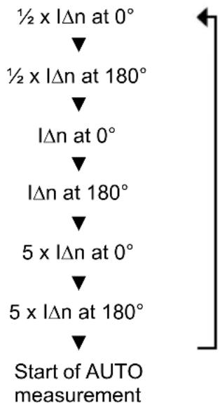
8.6.1 Tripping time RCDt (AUTO)
Automatic measurement of the tripping time is a test consequence of single measurements with different multipliers and initial polarities ( 0^/180^ ) of the nominal fault current ( I N ). The test is continued automatically each time the RCD is switched on again.
$$ \frac {1}{2} \times I \Delta N \text { at } 0 ^ {\circ}, \frac {1}{2} \times I \Delta N \text { at } 1 8 0 ^ {\circ} $$
$$ 1 \times I \Delta N \text { at } 0 ^ {\circ}, 1 \times I \Delta N \text { at } 1 8 0 ^ {\circ} $$
$$ 5 \times I \Delta N \text { at } 0 ^ {\circ}, 5 \times I \Delta N \text { at } 1 8 0 ^ {\circ} $$
- Select the desired function RCDt (AUTO) ① with the rotary switch ①.
- The symbols of the function keys F1 A to F4 D are briefly shown on the digital display ②. You can use the function keys F1 to F4 ③ to make the following settings:
F1 F2 F3 F4
-

IΔN
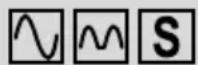
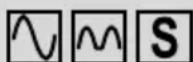
RCD type (F2):

sinusoidal test current

pulsating test current

selective (delayed) RCD
For testing selective RCDs, measurement starts after a time delay of 30 seconds.
flowchart
graph LR
    A["Waveform"] --> B["Sine Waveform"]
    B --> C["Waveform"]
    C --> D["Sine Waveform"]
    D --> E["Summing"]

(F3):
RECALL function; the measured values of the last AUTO measurement are shown on the digital display each time a key is pressed.
flowchart
graph TD
    A["½ x IΔn at 0°"] --> B["½ x IΔn at 180°"]
    B --> C["IΔn at 0°"]
    C --> D["IΔn at 180°"]
    D --> E["5 x IΔn at 0°"]
    E --> F["5 x IΔn at 180°"]
    F --> G["Start of AUTO measurement"]
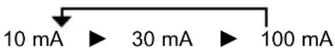
IΔN nominal fault current (F4):
Press the function key F4 to select the nominal fault current:
Available nominal fault currents (sinusoidal testing current)
- Connect the measuring leads to the BENNING IT 105 as shown in figures 4 or 5 and apply them to the test object.
- Press the TEST key ④ to start the measurement.
- Switch the RCD on again after each tripping until the test sequence is completed.
- Press the function key F4 ③ to call the tripping times of the different nominal fault currents on the main display K.
8.6.2 Tripping time RCDt (x ^1/2 , x1, x5)
- Use the rotary switch ① to select the multiplier (x½ ③, x1 Ⓚ, x5 ⑤) of the testing current for the desired function RCDt.
- The symbols of the function keys F1 A to F4 D are briefly shown on the digital display 2. You can use the function keys F1 to F4 3 to make the following settings:
F1 F2 F3 F4
0^ / 180^
- IΔN
0°/ 180° (F1):
0°: Testing current with positive initial polarity
180°: Testing current with negative initial polarity
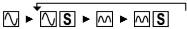
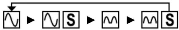
RCD type (F2):

sinusoidal test current

pulsating test current

selective (delayed) RCD
For testing selective RCDs, measurement starts after a time delay of 30 seconds.
flowchart
graph LR
    A["Waveform"] --> B["S"]
    B --> C["M"]
    C --> D["S"]
IΔN nominal fault current (F4):
Press the function key F4 to select the nominal fault current:
Available nominal fault currents (sinusoidal testing current)
10 mA 30 mA 100 mA 300 mA 500 mA
| 1/2 IΔN | √ | √ | √ | √ | √ |
| 1 IΔN | √ | √ | √ | √ | √ |
| 5 IΔN | √ | √ | √ |
- Connect the measuring leads to the BENNING IT 105 as shown in figures 4 or 5 and apply them to the test object.
- Press the TEST key ④ to start the measurement.
- The measured tripping time is shown on the main display K.
8.6.3 Tripping current RCDI
- Select the desired function RCDI Ⓜ with the rotary switch 1.
- The symbols of the function keys F1 A to F4 D are briefly shown on the digital display ②. You can use the function keys F1 to F4 ③ to make the following settings:
F1
F2
F3
F4
0^ / 180^

-
IΔN
0°/ 180° (F1):
0°: Testing current with positive initial polarity
180°: Testing current with negative initial polarity
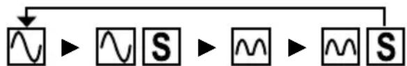
RCD type (F2):

sinusoidal test current

pulsating test current

selective (delayed) RCD
For testing selective RCDs, measurement starts after a time delay of 30 seconds.
flowchart
graph LR
    A["Waveform"] --> B["Sine Waveform"]
    B --> C["Waveform"]
    C --> D["Sine Waveform"]
IΔN nominal fault current (F4):
Press the function key F4 to select the nominal fault current:
Nominal fault currents at RCD type AC

- Connect the measuring leads to the BENNING IT 105 as shown in figures 4 or 5 and apply them to the test object.
- Press the TEST key ④ to start the measurement.
- The measured tripping time is shown on the main display Ⓚ.
9. Maintenance

Before opening the BENNING IT 105, ensure that it is not connected to a source of voltage! Electrical danger!
Any work required on the BENNING IT 105 when it is under voltage must be done only by a qualified electrician. Special steps must be taken to prevent accidents.
Before opening the BENNING IT 105, remove it from all sources of voltage as follows
- Turn the rotating switch ① to "OFF".
- Disconnect all connecting cables from the device.
9.1 Securing the installation tester
Under certain circumstances, the safety of the BENNING IT 105 can no longer be guaranteed. This may be the case if:
- there are visible signs of damage on the unit,
- errors occur in measurements,
- the unit has been stored for a long period of time under the wrong conditions, and
- if the unit has been subjected to rough handling during transport.
In these cases, the BENNING IT 105 must be switched off immediately, removed from the measuring points and secured to prevent it from being used again.
9.2 Cleaning
Clean the outside of the unit with a clean dry cloth. (Exception: any type of special cleaning cloth). Never use solvents or abrasives to clean the testing unit. Ensure that the battery compartment and the battery contacts have not been contaminated by electrolyte leakage.
If any electrolyte or white deposits are seen near to the battery or in the battery compartment, remove them with a dry cloth, too.
9.3 Battery replacement

Before opening the BENNING IT 105, ensure that it is not connected to a source of voltage! Electrical danger!
The BENNING IT 105 is powered by six 1.5 V mignon batteries (IEC LR6/ type AA).
Battery replacement is required as soon as the battery symbol ① is flashing on the display.
Proceed as follows to replace the batteries (see figure 8):
- Turn the rotating switch ① to "OFF".
- Lay the BENNING IT 105 face down and release the screws of the battery compartment cover.
- Lift the battery compartment cover off the bottom part.
- Remove the discharged batteries from the battery compartment.
- Insert the new batteries into the battery compartment at the provided places (please observe correct polarity of the batteries).
- Lock the battery compartment cover into place on the bottom part and tighten the screws.
See figure 8: Battery replacement

Remember the environment! Do not dispose of used batteries with domestic waste. Dispose of them at a battery-collection point or as toxic waste. Your local authority will give you the information you need.
9.4 Fuse replacement

Before opening the BENNING MM 12, ensure that it is not connected to a source of voltage! Electrical danger!
The BENNING IT 105 is protected against overload by means of an integrated fuse (1.6 A, 1000 V, superfast-acting (FF), breaking capacity ≥ 30 kA, D = 6.3 mm, L = 32 mm (part no. 10194027).
Proceed as follows to replace the fuses:
- Turn the rotating switch ① to "OFF".
- Lay the BENNING IT 105 face down and release the screws of the battery compartment cover.
- Lift the battery compartment cover off the bottom part.
- Laterally lift one side of the defective fuse off the fuse holder by means of a slotted screwdriver.
- Push the defective fuse out of the fuse holder completely.
- Insert a new fuse which has the same rated current, same rated voltage, same breaking capacity, same triggering characteristics and same dimensions.
- Lock the battery compartment cover into place on the bottom part and tighten the screws.
See figure 8: Fuse replacement
9.5 Calibration
Benning guarantees compliance with the technical and accuracy specifications stated in the operating manual for the first 12 months after the delivery date.
To maintain the specified accuracy of the measurement results, the instrument must be recalibrated at regular intervals by our factory service. We recommend a recalibration interval of one year. Send the unit to the following address:
Fuse 1.6 A, 1000 V, superfast-acting (FF), breaking capacity ≥ 30 kA, D = 6.3 mm, L = 32 mm part no. 10194027
10. Environmental notice

At the end of the product's useful life, please dispose of it at appropriate collection points provided in your country.
IΔN Nominale foutstroom (F4):
IΔN Nominale foutstroom (F4):
flowchart
graph LR
    A["Waveform"] --> B["Sine Wave"]
    B --> C["Sine Wave"]
    C --> D["Summing Junction"]