PYO-813 - Intercom Sygonix - Free user manual and instructions
Find the device manual for free PYO-813 Sygonix in PDF.
| Product type | Video intercom with camera and color monitor |
| Brand | Sygonix |
| Model | PYO-813 |
| Dimensions (indoor unit) | 235 x 120 x 28 mm (w x h x d) |
| Weight (indoor unit) | Approx. 700 g |
| Dimensions (outdoor unit) | 96 x 181 x 20 mm (w x h x d) |
| Weight (outdoor unit) | Approx. 400 g |
| Power supply | AC adapter 100-240 V~, 50/60 Hz, output 17 V⎓, 1.5 A |
| Power consumption (indoor unit) | Standby approx. 2 W, in operation max. 14 W |
| Display | Diagonal 175 mm (7"), resolution 480 x 234 |
| Viewing angle (camera) | 57.8° horizontal, 48.6° vertical |
| Night vision | Yes, 6 white LEDs with auto activation |
| Ring tones | 4 selectable melodies |
| Number of door openers | 2 max (1 direct + 1 via potential-free relay) |
| System capacity | Up to 2 indoor units and 2 outdoor units |
| Connection cable type | Two-core cable (not supplied) |
| Max. distance outdoor-indoor unit | 50 m with 1 mm² cross-section, 100 m with 1.5 mm² |
| Protection rating (outdoor unit) | IPX4 |
| Operating temperature (outdoor unit) | -20 °C to +50 °C |
| Operating temperature (indoor unit) | 0 °C to +40 °C |
| Maintenance and cleaning | Clean with a soft dry cloth; do not use aggressive cleaners |
| Spare parts and repairability | No user-serviceable parts; repair exclusively by a specialist |
| Safety | Follow safety instructions: do not expose to moisture or shocks; do not modify the device |
| General information | Intended use: access control for private homes |
Frequently Asked Questions - PYO-813 Sygonix
User questions about PYO-813 Sygonix
0 question about this device. Answer the ones you know or ask your own.
Ask a new question about this device
Download the instructions for your Intercom in PDF format for free! Find your manual PYO-813 - Sygonix and take your electronic device back in hand. On this page are published all the documents necessary for the use of your device. PYO-813 by Sygonix.
USER MANUAL PYO-813 Sygonix
Operating Instructions
Video Door Intercom
Item No. 1656670 Page 23 - 43
Notice d'emploi
Interphone vidéo
www.business.conrad.at
natural_image
Technical line drawings of two electronic devices labeled A and B, showing internal components and wiring (no text or symbols beyond labels)natural_image
Technical diagram of a brick wall-mounted device with screw fasteners and a close-up view of the internal components (no text or symbols)
- Introduction....24
- Explanation of symbols....24
- Intended use....25
- Scope of delivery 25
- Safety information....26
a) General information....26
b) Mains adapter....27
c) Indoor unit....27
d) Outdoor unit....27
- Control elements and connections ......28
a) Indoor unit....28
b) Outdoor unit....29
- Installation....30
a) General information....30
b) Connection chart A (one outdoor unit + one indoor unit)....31
c) Connection chart B (two outdoor units + two indoor units)....32
d) Installation of the outdoor unit 34
e) Label name tag....36
f) Installation of the indoor unit....37
- Commissioning and operation 38
a) Visitor rings at the outdoor unit....38
b) Activating outdoor unit from indoor unit 39
c) Talking between the indoor units 39
d) Operating door opener 39
e) Changing the bell tone....40
f) Changing settings for the colour display....40
g) Activating/deactivating muting 40
h) Setting the volume....40
-
Troubleshooting 41
-
Maintenance and cleaning....42
- Disposal 42
- Technical data....42
a) Indoor unit....42
b) Outdoor unit....43
c) Mains adapter....43
1. Introduction
Dear Customer,
thank you for purchasing this product.
This product complies with the statutory national and European requirements.
To maintain this status and to ensure safe operation, you as the user must observe these operating instructions!

These operating instructions are part of this product. They contain important notes on commissioning and handling. Also consider this if you pass on the product to any third party.
Therefore, retain these operating instructions for reference!
All company names and product names are trademarks of their respective owners. All rights reserved.
If there are any technical questions, please contact:
International: www.conrad.com/contact
United Kingdom: www.conrad-electronic.co.uk/contact
2. Explanation of symbols

The symbol with a lightning bolt in a triangle is used where there is a health hazard, e.g. from electric shock.

The exclamation mark in a triangle indicates important notes in these operating instructions that must be observed strictly.

The arrow symbol indicates that special advice and notes on operation are provided.
3. Intended use
The product is suitable for access control, e.g. in the private residential area.
A camera and a speaker/microphone in the outdoor unit (6 white LEDs are integrated for operation at darkness), and a colour display in the indoor unit make it possible to check who is in front of the door. If the visitor is welcome, you can push the door opener to let your visitor in.
As a special feature, you can connect two door openers to the outdoor unit on demand, e.g. for the front door and the entrance gate/garden gate to the property. Both door openers can be pushed separately.
It is also possible to connect two indoor units and two outdoor units to each other, and to thus monitor two entrance areas and open the corresponding doors.
Power is supplied through an enclosed plug-in mains adapter; the connection between the outdoor and the indoor unit takes place via a two-wire cable.
The safety information must be observed at all times!
Any use other than that described above can damage the product and may involve additional risks such as short circuit, fire, electric shock, etc. No part of this product must be modified or converted!
This product complies with the statutory national and European requirements. All company names and product names are trademarks of their respective owners. All rights reserved.
4. Scope of delivery
- Outdoor unit
- Indoor unit
• Wall holder (may be pre-installed at the rear of the indoor unit at delivery) - Mounting material (6x screws and 6x dowels)
- Plug-in mains adapter
- Operating instructions
Up-to-date operating instructions
To download the latest operating instructions, visit www.conrad.com/downloads or scan the QR code on this page. Follow the instructions on the website.

5. Safety information

The warranty/guarantee will expire if damage is incurred resulting from non-compliance with these operating instructions. We do not assume any liability for consequential damage!
We do not assume any liability for property damage and personal injury caused by improper use or non-compliance with the safety instructions! In such cases the guarantee/warranty will expire!
a) General information
- For safety and approval reasons, unauthorised conversion and/or modification of the device are not permitted.
- The product is not a toy and must be kept out of reach of children.
- Handle the product with care. It can be damaged by impact, blows or when dropped even from a low height.
- If you find any damage at the product, stop operating it and take it to a specialist workshop or dispose of it environmentally compatibly.
-
It can be assumed that safe operation is no longer possible if:
-
the product is visibly damaged
- the product no longer functions
- the product has been stored under unfavourable conditions for an extended period of time
- if it was subjected to heavy stress during transport
- If the product is brought from a cold into a warm room (e.g. in transport), it is possible that condensation develops.
Therefore, first let the product reach room temperature before connecting it to the power supply. This may take several hours.
In case of moisture on the plug-in mains adapter, there is danger to life from electric shock!
- Do not leave packaging material unattended. It may become a dangerous toy for children.
- In commercial institutions, the accident prevention regulations of the Employer's Liability Insurance Associations for Electrical Systems and Operating Materials are to be observed.
- If there are any questions that are not answered in this operating manual, contact our technical support or another expert.
b) Mains adapter
- The mains adapter is constructed pursuant to protection category II.
- Only connect the mains adapter to proper mains sockets of the public mains.
- The mains socket for the plug-in mains adapter must be close to the indoor unit and easily accessible.
- The plug-in mains adapter is intended for use in a dry, closed indoor room; it must not become damp or wet. There is danger to life from electric shock!
- Do not pull the plug-in mains adapter from the mains socket by pulling the cable.
- Protect the cables of the plug-in mains adapter from sharp edges, do not step on them.
- If the mains adapter is damaged, do not touch it. Danger to life from electric shock!
First deactivate all sides of the mains socket to which the plug-in mains adapter is connected (e.g. switch off the respective fuse or turn out the fuse. Then deactivate the associated FI protection switch).
Then unplug the mains adapter from the mains socket. Replace the damaged plug-in mains adapter with a new one of the same build.
c) Indoor unit
- The indoor unit is only suitable for dry, closed rooms. Do not expose it to direct sunlight, heat, cold, dust, dirt dampness or wetness; otherwise, it will be damaged.
- Never cover the ventilation openings on the back.
- Do not push the display surface too hard. This will not only leave scratches, but the display may also break and be permanently damaged. Loss of guarantee/warranty!
d) Outdoor unit
- The outdoor unit is suitable for indoor and outdoor use (IPX4). However, it must never be operated in or under water; it would be destroyed by this.
• Install the outdoor unit in the outdoor area under an advancing roof (e.g. an awning). - Ensure that the connection cables are not crushed, bent or damaged by sharp edges.
- Install the outdoor unit so that the integrated camera does not point right at bright light sources (e.g. the sun or spotlights). This will not only cause an overmodulated and useless image, but also may damage the image sensor it permanently exposed.
- Before installation of the outdoor unit, observe any applicable provisions for whether operation of the camera or its alignment with a specific area of the environment is permitted.
6. Control elements and connections
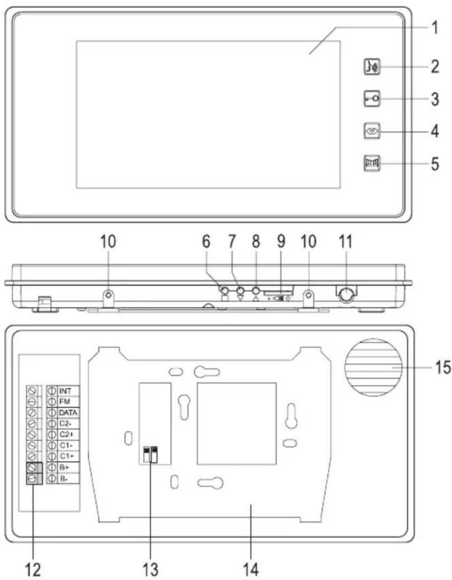
a) Indoor unit
text_image
1 2 3 4 5 10 6 7 8 9 10 11 INT FM DATA C2- C2+ C1- C1+ B+ B- 12 13 14 151 Colour display
2 Button " , "
3 Button " "
4 Button " "
5 Button " "
6 Button " "
7 Button " " ▲
8 Button "▼
9 Setting controller for volume
10 Screws to attach the indoor unit to the wall holder
11 Microphone
12 Screw terminals
13 DIP-switch for master/slave
14 Wall holder
15 Speaker
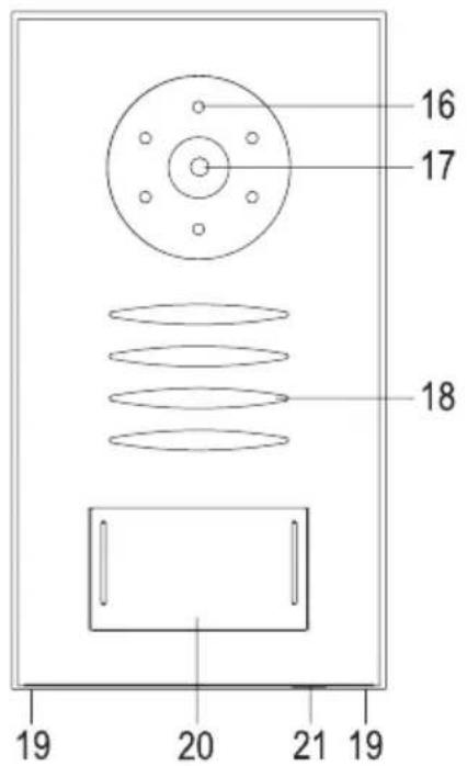
b) Outdoor unit
16 White LEDs (activated automatically at low ambient brightness)
17 Camera lens
18 Speaker
19 Attachment screws for the front plate
20 Ringing button with name tag
21 Microphone
text_image
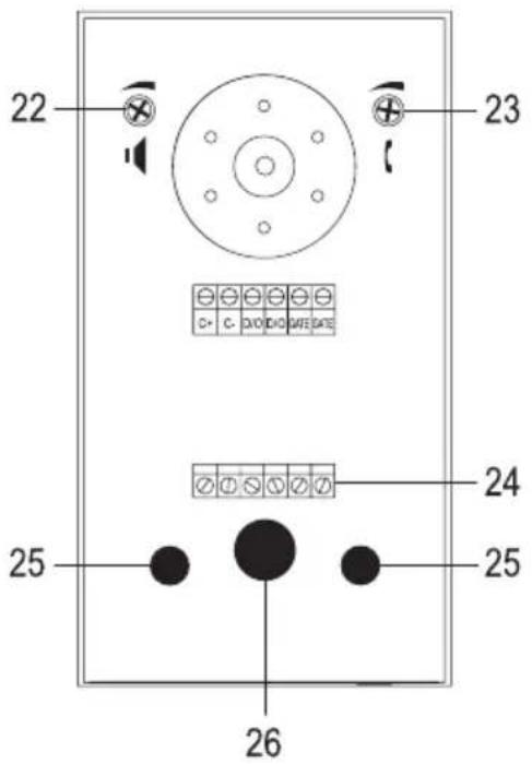
16 17 18 19 20 21 19After removal of the front plate (turn out the two screws (19), then lever off the front plate), the following operating elements/connections are accessible:
22 Dial switch for setting the playback volume via the speaker of the outdoor unit
23 Dial switch for setting the microphone sensitivity
24 Screw terminals
25 Doorbell button
26 Cable penetration (with rubber seal)
text_image
22 23 24 25 267. Installation
a) General information
The outdoor unit should be installed in the protected area, e.g. next to the front door (e.g. under an awning) so that the visitor is standing right in front of it when he presses the doorbell button. The camera should be installed approx. at a height of 150 cm, depending on the ambient conditions at the installation site.
The indoor unit is only suitable for installation in a dry, closed inner room, e.g. on the inside of the corridor. The installation height should be approx. 140 cm.
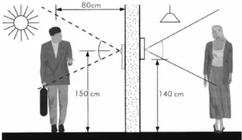
text_image
80cm 150 cm 140 cmPlace a two-wire cable (not included) between the outdoor and the indoor unit.
The wider the distance between the outdoor and the indoor units, the larger the cable cross-section has to be. Otherwise, the outdoor unit may not work.
Cable length up to 50 m: Cross-section 1 mm²
Cable length up to 100 m: Cross-section 1.5 mm²
If two indoor units are connected to each other, a cable with a cross-section of 1.5 mm^2 must be used (cable length up to 20 m).
A door opener (e.g. for the front door) and a gate opener (e.g. for the entrance gate to the property) can be connected to the outdoor unit directly.

Test the video door intercom system at the future installation site before drilling holes for fixed mounting and placing cables. For this test, the same cable should be used at the corresponding length that you will later use for connection of the outdoor and indoor units.
Install the outdoor and indoor units only on stable surfaces, but not on metal ones or near other electrical/electronic devices.
Ensure that no cables or lines are damaged when drilling or screwing. The same applies when placing connection cables and any masonry work required because of this.
Do not place the connection cable between the outdoor and indoor unit right next to other power cables or lines; do not place it on or near metal faces. This may negatively affect transmission.
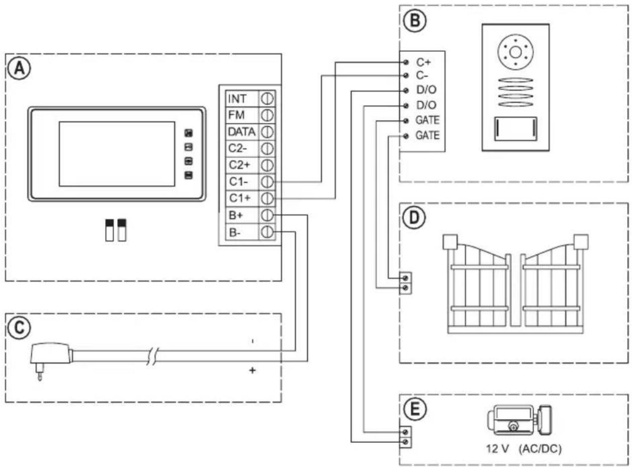
b) Connection chart A (one outdoor unit + one indoor unit)
flowchart
graph TD
    A["Device"] -->|INT ① FM ① DATA ① C2- ① C2+ ① C1- ① C1+ ① B+ ① B-| B["Control Panel"]
    B -->|C+ C- D/O D/O GATE GATE| C["Re-Yield Display"]
    B -->|D ①| D["Bay/Window"]
    B -->|E ②| E["AC/DC 12V"]
The indoor unit (A) and the outdoor unit (B) is connected via a two-wire cable as shown above. Power is supplied by the included mains adapter (C).
The two small DIP switches (see figure in chapter 6. a, item 13) on the rear of the indoor unit (A) must be in the upper position.
A door opener (E) can be connected directly, since the outdoor unit provides the operating voltage right at the two connection terminals "D/O".
The connection terminals "GATE", in contrast, are potential-free. If another door opener is to be connected, e.g. for an entrance gate (D) to the property, you need to provide the operating voltage with an external mains unit.

Always observe the contact resilience of the relay for the connection terminals "GATE" in the outdoor unit (see chapter "Technical Data").
Never switch the mains voltage via the connection terminals "GATE"! There is danger to life from electric shock!
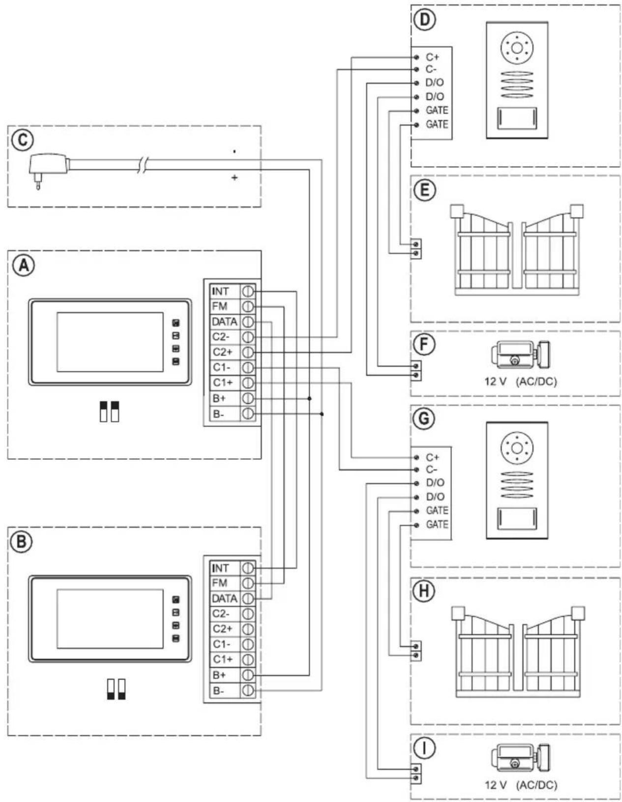
c) Connection chart B (two outdoor units + two indoor units)
flowchart
graph TD
    subgraph_Component_A["Component A"]
        A1["AC Source"] -->|+| B1["INT ① FM ① DATA ① C2- ① C2+ ① C1- ① C1+ ① B+ ① B-"]
    end
    subgraph_Component_B["Component B"]
        B1 -->|+| C1["INT ① FM ① DATA ① C2- ① C2+ ① C1- ① C1+ ① B+ ① B-"]
    end
    subgraph_Component_C["Component C"]
        C1 -->|+| D1["C+ C- D/O D/O GATE GATE"]
    end
    subgraph_Component_E["Component E"]
        E1["12 V (AC/DC)"]
    end
    subgraph_Component_F["Component F"]
        F1["F"]
    end
    subgraph_Component_G["Component G"]
        G1["C+ C- D/O D/O GATE GATE"]
        G2["12 V (AC/DC)"]
    end
    subgraph_Component_H["Component H"]
        H1["H"]
    end
    subgraph_Component_I["Component I"]
        I1["I"]
    end
The version with two outdoor and indoor units each may be used if your house has two entrances, for example.
The indoor unit 1 (A) and the outdoor unit 2 (B) are connected via the corresponding wires as shown in the connection chart. Power is supplied through a plug-in mains adapter (C).

The two small DIP switches (see figure in chapter 6. a, item 13) on the rear of the two indoor units must be set accordingly.
Indoor unit 1 (A): Upper position (= "Master")
Indoor unit 2 (B): Lower position (= "Slave")
One door opener (F and I) can each be connected directly to each of the two outdoor units (D and G)(operating voltage 12 V), since the outdoor units provide the operating voltage at the two connection terminals “D/O” directly.
The connection terminals "GATE", in contrast, are potential-free. If another door opener is to be connected here, e.g. for an entrance gate (E and H) to the property, provide the operating voltage with an external mains unit.

Always observe the contact resilience of the relay for the connection terminals "GATE" in the outdoor unit (see chapter "Technical Data").
Never switch the mains voltage via the connection terminals "GATE"! There is danger to life from electric shock!
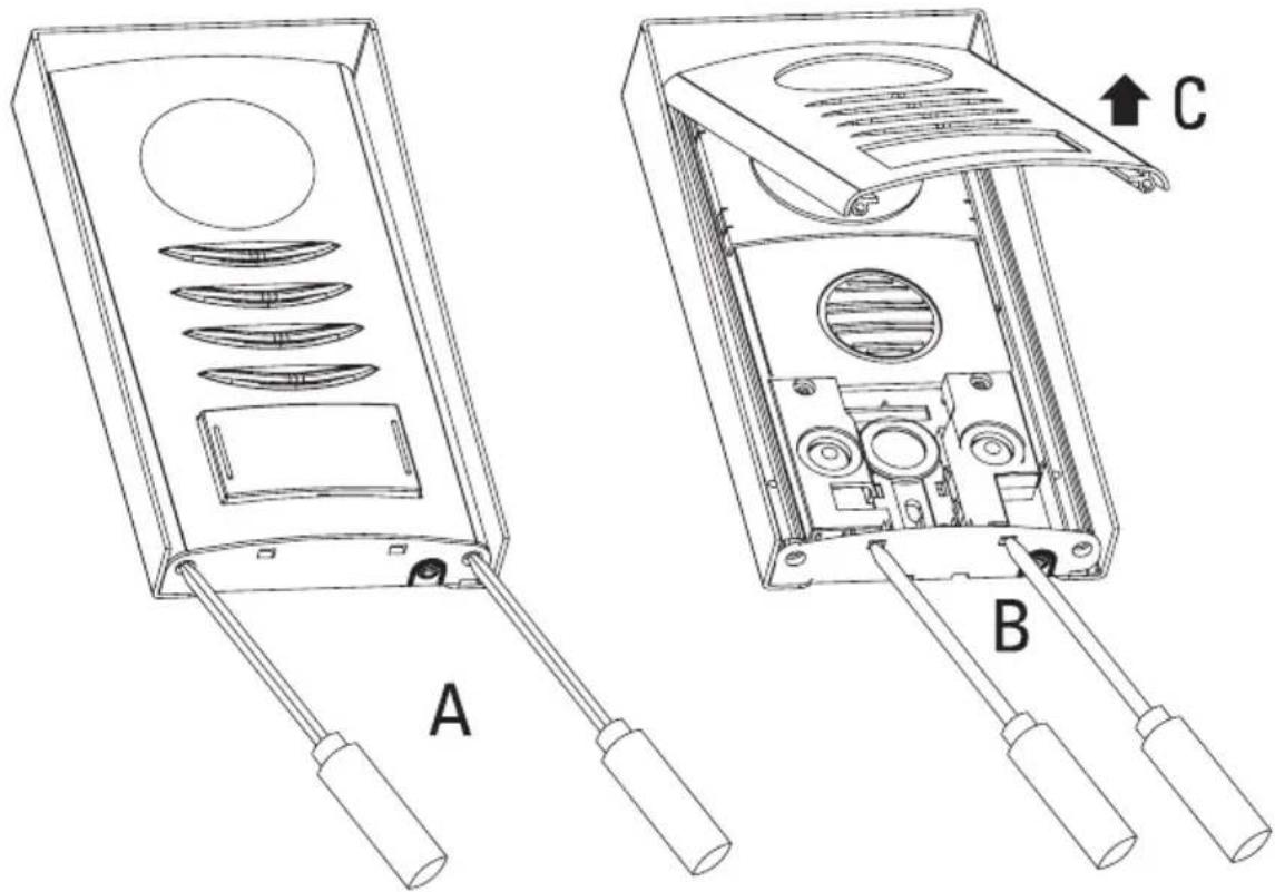
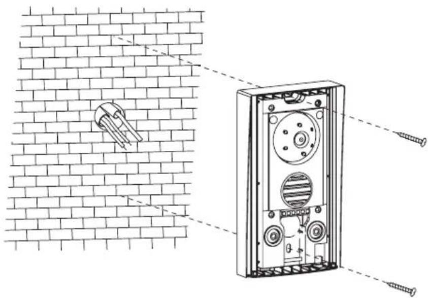
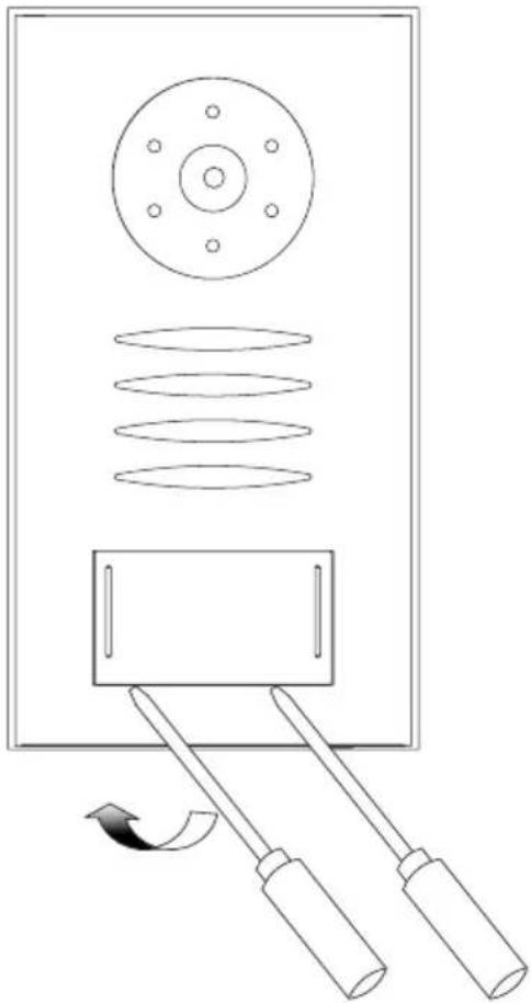
d) Installation of the outdoor unit
- First turn out the two attachment screws (19) for the front plate with a Phillips-head screwdriver, see figure "A".
- Carefully push a flat screwdriver into the two openings, see figure "B"; this loosens the clamp holder of the front plate.
Fold up the front plate a little (C) and take it off.
natural_image
Technical line drawings of two electronic device modules labeled A and B, showing internal components and wiring (no text or symbols beyond labels)• Guide the connection cables through the rubber seal (26).
- Attach the outdoor unit to the wall with two suitable screws and, if required, dowels. The camera must be on top as shown in the figure.
natural_image
Technical diagram of a brick wall assembly with screw fasteners and a mounted component (no text or symbols)
Ensure that no cables or lines are damaged when drilling or screwing.
suitable sealing where the cable comes out of the wall, so that water running down the wall (e.g. rain) cannot run into the wall along the cable. Use a little silicone for sealing.
- Connect the cables as in the connection chart in chapter 6. b) or 6. c).

Always observe proper polarity for the terminals “C+” and “C-”, since otherwise both the indoor unit and the outdoor unit will be damaged; loss of warranty/guarantee!
The polarity does not matter in conventional door openers, in contrast.
Observe that a door opener (operating voltage 12 V) can be connected directly to the screw terminals "D/O". No further external wiring is necessary.
The screw terminals "GATE" in contrast are potential-free. Only an internal relay is switched here (for contact resilience, see chapter "Technical data").
- Alignment of the camera can be set. For this, the round camera housing can be carefully turned to the left, right, up or down.
- The dial switch (22) can be used to set the playback volume via the speaker (turn to the left counter-clockwise = volume down, turn to the right clockwise = volume up). For initial commissioning, do not adjust the dial switch.
- The dial switch (23) can be used to set the microphone sensitivity and thus indirectly the volume on the indoor unit (turn to the left counter-clockwise = reduce sensitivity, turn to the right clockwise = increase sensitivity). For initial commissioning, do not adjust the dial switch.
- Put on the front plate again and carefully push it into the clamp holder so that the bottom edge of the front plate ends flush with the lower plastic edge.
- Fasten the front plate with the two screws removed before (19).

Observe that you do not accidentally turn the right screw into the opening for the microphone labelled "mic"! Loss of guarantee/warranty!
- To protect from moisture, apply a little silicone on the upper end of the outdoor unit between the aluminium frame and the wall. This prevents that water running down the wall will run along the cable and into the outdoor unit.
e) Label name tag
- To label the name tag, the transparent plastic cover must be removed. This is only clipped on.
Carefully lever off the plastic cover with a flat screwdriver by carefully pushing the screwdriver into the slot between the cover and the front plate. - Label the name sign with a water-resistant pen; alternatively, you can also make a dedicated sign (53 x 28 mm) with a laser printer.
- Put the name tag into the plastic cover and attach it again.
natural_image
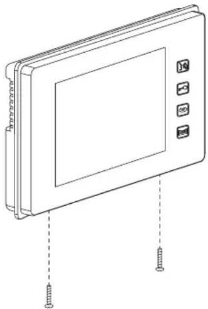
Diagram of a mechanical device with rollers and two lever arms, showing motion direction (no text or symbols)f) Installation of the indoor unit
- First turn out the two attachment screws (10) for the wall holder with a Phillips-head screwdriver.
- Then remove the wall holder (14) on the rear of the indoor unit. Remember the orientation.
natural_image
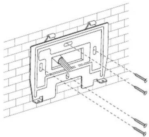
Line drawing of a rectangular electronic device with four buttons and two screws inserted (no text or symbols)- Guide the connection cables through the opening of the wall holder (14).
- Attach the wall holder to the wall with four screws and, if required, dowels.
Observe correct alignment of the wall holder, see figure to the right.
natural_image
Technical line drawing of a mechanical bracket mounted on a brick wall, with screw fasteners visible (no text or symbols)
Ensure that no cables or lines are damaged when drilling or screwing.
- Connect the cables as in the connection chart in chapter 6. b) or 6. c).

Observe correct polarity, since the indoor unit and the outdoor unit will be damaged otherwise. Loss of warranty/guarantee!
- Put the indoor unit onto the wall holder and fasten it with the two screws (10) removed at the start.
8. Commissioning and operation
If you have put the outdoor and the indoor unit next to each other for testing, observe that there may be loud feedback loop sounds via the microphone and speaker in this case.
This behaviour is normal.
Just keep a distance of several metres between the outdoor unit and the indoor unit to avoid such feedback loops when testing. Alternatively, put several pieces of insulation tape on top of each other over the microphone opening temporarily.
Plug the enclosed plug-in mains adapter into a proper mains socket.
The LEDs for the sensor buttons on the indoor unit and the LEDs for lighting of the bell button light up; the video door intercom system is then ready for operation.

If the LEDs do not light up, pull the plug-in mains adapter from the socket again at once and check the wiring.
a) Visitor rings at the outdoor unit
- When a visitor pushes the doorbell button at the outdoor unit, standby mode is terminated and the camera in the outdoor unit switches on (depending on the ambient brightness, the white LEDs will light up). The camera image appears on the indoor unit monitor.
A bell tone also comes from the speaker of the outdoor and indoor unit.
The bell tone ends automatically after 15 seconds. The image on the display of the indoor unit goes out after 30 seconds if you do not want to talk to the visitor. Then the video door intercom system returns to standby mode.
- Push the button "3(2) to talk to the visitor.
The outdoor and indoor units remain activated for approx. 80 seconds before automatically returning to standby mode.
- To activate the door opener, push the button “-” (3).
If you want to activate the door opener so that it will, e.g., open the entrance gate, push the button "☐(5).
Both the display and the LEDs in the outdoor unit will go out for a few seconds if you activate one of the two door openers.
The time for activation of the door opener is 3 seconds (cannot be changed).
If you have two outdoor units, the door opener that is connected to the outdoor unit for which the camera image is visible will be activated.
- To end the talk, push the button “☐” (2). The display on the indoor unit goes out, the video door intercom system is back in standby mode.
- If the connection has been terminated prematurely (e.g. because the video door intercom system switched into standby mode automatically after 80 seconds) and you want to resume it, briefly push the button “☐” (4) and then the button “☐(2).
The outdoor and indoor units remain activated for approx. 80 seconds before automatically returning to standby mode.
b) Activating outdoor unit from indoor unit
- Briefly push the button “☐”(4) to display the camera image.
If you have two outdoor units, push the button " " (4) again to switch to the respective other outdoor unit.
If you have only connected one outdoor unit and push the button several times, you may see a black image for a few seconds and hear noise in the speakers before it switches back to the other outdoor unit.
- Push the button "3(2) to talk to the visitor.
- To activate the door opener, push the button "☐"(3).
If you want to activate the door opener so that it will, e.g., open the entrance gate, push the button "F(5).
Both the display and the LEDs in the outdoor unit will go out for a few seconds if you activate one of the two door openers.
The time for activation of the door opener is 3 seconds (cannot be changed).
If you have two outdoor units, the door opener that is connected to the outdoor unit for which the camera image is visible will be activated.
- To end the talk, push the button “☐” (2). The display on the indoor unit goes out, the video door intercom system is back in standby mode.
The outdoor and indoor units remain activated for approx. 80 seconds before returning to standby mode.
- If the talk was terminated by accident and you want to resume it, briefly push the button “💡” (4) and then the button “💡2).
c) Talking between the indoor units
This is only possible if you operate two indoor units, see chapter 7. c).
The indoor units also must be in standby mode. You must not be talking to one of the outdoor units during this.
- Push the button "3(2). A special bell tone is issued on the indoor units.
- To accept the call, push the button "34(2). Now you can talk between the indoor units.
The two indoor units remain activated for approx. 150 seconds before automatically returning to standby mode.
• To end the talk, push the button "3(2).
d) Operating door opener
→ Activation of a door opener is only possible if a camera image is displayed on the display of the indoor unit.
Proceed as described in chapter 8. b).
e) Changing the bell tone
The bell tone can be changed if the video door intercom system is in standby mode. It does not work while talking to one of the outdoor units.
- Push the button "☐" (3) to play the current bell tone.
- Use the button “(4) to select one of 4 different bell tones.
- Confirm the selected bell tone with the button “-”(3).
f) Changing settings for the colour display
The setting menu can only be called if the colour display is showing an image. For this, e.g. push the button " (4).
- If the display of the indoor unit shows the camera image, push the button "■" (6), to call the setting menu.
- Use the button "■(6) to switch between
"Brightness": Setting the brightness
"Contrast": Setting the contrast
"Color": Setting colour saturation
"Exit": Leaves the setting menu
→ The current selection is marked in colour in each case.
- If "Brightness", "Contrast" or "Color" is selected, you can change the settings with the buttons "▲" (7) or "▼" (8). If "Exit" is selected and you push the button "▲(7) or " " (8), you will leave the setting menu.
The setting menu is also left automatically if no button is pushed for a few seconds.
g) Activating/deactivating muting
→ Activating/deactivating muting is only possible if the video door intercom system is in standby mode. It does not work while talking to one of the outdoor units.
With muting active, the indoor unit will not play the bell tone. Muting can be used, e.g. at night, when you do not want to be disturbed.
- Push the button "☐(5) to activate muting.
A red LED flashes in the button "☐"
- To deactivate muting again, push the button "☐(5) again. The red LED goes out.
h) Setting the volume
- The playback volume at the indoor unit can be set with the controller (9).
- The playback volume at the outdoor unit can be set with the dial switch (22) (turn to the left counter-clockwise = volume down, turn to the right clockwise = volume up).
- The dial switch (23) can be used to set the microphone sensitivity and thus indirectly the volume on the indoor unit (turn to the left counter-clockwise = reduce sensitivity, turn to the right clockwise = increase sensitivity).
9. Troubleshooting
No picture, no sound
- Check the voltage/power supply (plug-in mains adapter) and the correct wiring of the outdoor and indoor unit.
Door opener does not work
- Check the correct wiring of the door opener at the outdoor unit.
- The video-door intercom may control two door openers.
Note that the door opener connected to the screw terminals "D/O" is supplied with voltage/power directly (12 V, max. 1 A) if you push the button "(8).
The screw terminals "GATE" in contrast are potential-free. Only an internal relay is switched here (for contact resilience, see chapter "Technical data"). If a door opener is to be actuated at the screw terminals "GATE", you need an additional external voltage/power supply for the door opener.
When pushing the door opener, the display will go out for a few seconds.
- This is normal.
Flickering image on the indoor unit display
- This is caused, e.g. by counter-light or mirroring objects in the area of the outdoor unit's camera. Align the camera in the outdoor unit differently if necessary.
Image too light or too dark, bad colours
- Adjust the brightness, contrast and colours in the setting menu of the indoor unit, see chapter 8. f).
10. Maintenance and cleaning
The product is maintenance-free for you. Servicing or repair must only be carried out by a specialist or specialist workshop. The product contains no parts that require maintenance by you.
A dry, soft and clean cloth is sufficient for cleaning the outside.
Clean the transparent cover of the camera in the outdoor unit and the front of the indoor unit very carefully in order not to scratch them. Do not push the display too hard!
Remove dust on the indoor unit with a long-haired, soft and clean brush and a vacuum cleaner.
Never use any aggressive cleaning agents, cleaning alcohol or other chemical solutions, since these may damage the casing or even impair function.
11. Disposal

The product does not belong in the household waste!
e of the product according to the relevant statutory regulations at the end of its service life.
12. Technical data
a) Indoor unit
Operating voltage 17 V/DC
Power intake....Standby approx. 2 W, operation max. 14 W
Display....153 x 85 mm (W x H), diagonal 175 mm (7")
Resolution....480 x 234 (horizontal x vertical)
Connection cable type....2-wire (between outdoor and indoor unit)
Cable length between
outdoor and indoor unit ......max. 50 m at cable cross-section 1 mm ^2
max. 100 m at cable cross-section 1.5 mm ^4
Cable length between
two indoor units ......max. 20 m at cable cross-section 1.5 mm ^2
Cable length between
outdoor and door opener ....max. 20 m at cable cross-section 1.5 mm ^2
Ambient conditions....temperature 0 °C to +40 °C, humidity 10% to 90% relative, non-condensing
Installation/operation site......In dry, closed inner rooms only
Dimensions....235 x 120x 28 mm (W x H x D)
Weight .....approx. 700 g
b) Outdoor unit
Operating voltage ....12 V/DC, via connection cable from the indoor unit
Power intake....max. 3 W
Image sensor 6,35 mm (1/4"), CMOS
Effective resolution 648 x 488 (horizontal x vertical)
TV-lines....700
Focal width 2.3 mm
Opening angle 57.8° horizontal, 48.6° vertical
Alignment adjustable ....Yes (camera swivels horizontally and vertically)
Operation in darkness ....Yes, with 6 white LEDs (automatic activation at low ambient brightness when the doorbell is pushed)
Bell button lit....Yes (2 blue LEDs)
Relay contact resilience
for connection "GATE"....Max. 12 V (AC/DC), max. 1 A; potential-free closer contact via relay (NO contact)
Suitable door opener for connection "D/O".....12 V (AC/DC), max. 1 A
Protection degree IPX4
Ambient conditions Temperature -20 °C to +50 °C
Installation/operation site....protected outdoor area
Dimensions....96 x 181 x 20 mm (W x H x D)
Weight .....approx. 400 g
c) Mains adapter
Operating voltage 100 - 240 V/AC, 50/60 Hz
Output....17 V/DC, 1.5 A
Page
France (email) : technique@conrad-france.fr
natural_image
Technical line drawings of two electronic device modules labeled A and B, showing internal components and wiring (no text or symbols beyond labels)natural_image
Technical diagram of a brick wall assembly with internal components and screw fasteners (no text or labels)
Tension de service....17 VICC
1 Kleurenmonitor
2 Toets, "
3 Toets, "
4 Toets , "
5 Toets, "
6 Toets, "■
7 Toets, "▲
8 Toets, "▼
natural_image
Technical line drawings of two electronic device components labeled A and B, showing internal wiring and mounting holes (no text or symbols beyond labels)natural_image
Technical diagram of a brick wall-mounted electrical panel with screw fasteners and a close-up view of the component (no text or symbols)
natural_image
Diagram of a mechanical device with rollers and two lever arms, showing motion direction (no text or symbols)natural_image
Line drawing of a rectangular electronic device with four buttons and two screws inserted (no text or symbols)natural_image
Technical line drawing of a mechanical bracket assembly mounted on a brick wall, with screws and fasteners visible (no text or labels)
This is a publication by Conrad Electronic SE, Klaus-Conrad-Str. 1, D-92240 Hirschau (www.conrad.com).
All rights including translation reserved. Reproduction by any method, e.g. photocopy, microfilming, or the capture in electronic data processing systems require the prior written approval by the editor. Reprinting, also in part, is prohibited. This publication represents the technical status at the time of printing.
Copyright 2018 by Conrad Electronic SE.
Copyright 2018 by Conrad Electronic SE.
Copyright 2018 by Conrad Electronic SE.