EM4159 - Intercom Sygonix - Free user manual and instructions
Find the device manual for free EM4159 Sygonix in PDF.
User questions about EM4159 Sygonix
0 question about this device. Answer the ones you know or ask your own.
Ask a new question about this device
Download the instructions for your Intercom in PDF format for free! Find your manual EM4159 - Sygonix and take your electronic device back in hand. On this page are published all the documents necessary for the use of your device. EM4159 by Sygonix.
USER MANUAL EM4159 Sygonix
GB Operating Instructions
Wireless video door phone
Item No. 1698497 Page 31 - 59
F Notice d'emploi
Interphone vidéo
text_image
Diagram of a device's internal structure and assembly, labeled with components A, B, C, D and directional arrows indicating assembly steps.text_image
Diagram showing a device being inserted into a triangular base panel, with Chinese annotation indicating the process.natural_image
Line drawing of a remote control tower with buttons and a base (no text or symbols)text_image
Technical diagram of an electronic device with labeled components including battery, casing, and internal compartmentsc) Anschlussschema

Wichtig!
text_image
Technical diagram of a mobile phone casing with labeled components A, B, and Ctext_image
Volume Brightness Key Tone Ring Tone Select Back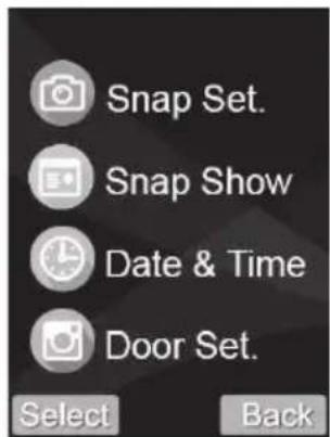
text_image
Snap Set. Snap Show Date & Time Door Set. Select Back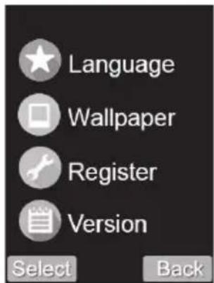
text_image
Language Wallpaper Register Version Select Back
text_image
Default Set. Select Backtext_image
Technical diagram of a device showing internal components with labeled parts A and B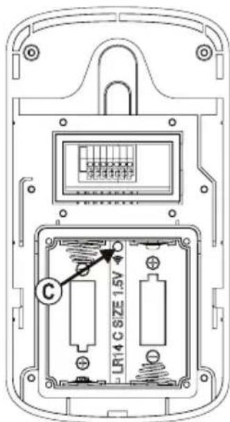
text_image
LR14 C SIZE 1.5V Ctext_image
Technical diagram of a device showing internal components with labeled parts A and B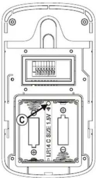
text_image
C LR14 C SIZE 1.5Vwww.conrad.com/downloads
- Introduction......33
- Explanation of symbols....33
- Intended use 34
- Package contents 34
- Safety instructions ....35
a) General information....35
b) Power adapter 36
c) Handset 36
d) Charging station 37
e) Outdoor unit....37
f) Li-Ion Rechargeable Battery....37
- Controls and Connections ...... 38
a) Outdoor unit....38
b) Handset 39
c) Charging station 40
- Commissioning the handset 41
a) Insert the battery into the handset 41
b) Connecting the charging station....41
c) Plug the handset into the charging station, charge the rechargeable battery 42
- Assembly/connection of the outdoor unit....43
a) General information....43
b) Operation via batteries, insert/change batteries....43
c) Wiring diagram 44
d) Assembly of the outdoor unit 45
- Setup and operation 46
a) General information....46
b) Switching the handset on/off, standby function 46
c) Call up and operate the setting menu....47
-
Register the outdoor unit to the handset....51
-
Operation....53
a) Visitor rings at the outdoor unit....53
b) Activate the outdoor unit from the handset (monitor function)....53
c) Activate the monitor function during battery operation 54
d) Operating the door opener 55
e) Sabotage alarm when removing the outdoor unit....55
f) Activate the door opener via push button 55
Page
- Troubleshooting....56
- Declaration of Conformity (DOC)....57
- Disposal 57
a) Product 57
b) (Rechargeable) batteries....57
- Care and cleaning....58
- Technical data....58
a) General information....58
b) Handset....58
c) Outdoor unit....59
d) Power adapter 59
e) Charging station 59
1. Introduction
Dear customer,
Thank you for purchasing this product.
These products comply with statutory, national and European regulations.
To ensure that the product remains in this state and to guarantee safe operation, always follow the instructions in this manual.

These operating instructions are part of this product. They contain important information on setting up and using the product. Do not give this product to a third party without the operating instructions. Keep these operating instructions for reference!
All company and product names are trademarks of their respective owners. All rights reserved.
If there are any technical questions, please contact:
International: www.conrad.com/contact
United Kingdom: www.conrad-electronic.co.uk/contact
2. Explanation of symbols

The symbol with the lightning in a triangle indicates that there is a risk to your health, e.g. due to an electric shock.

The symbol with an exclamation mark in a triangle is used to highlight important information in these operating instructions that must be observed.

The arrow symbol indicates special information and tips on how to use the product.
3. Intended use
The intercom is suitable for access monitoring, e.g. to private living quarters.
By means of a camera and a speaker/microphone in the outdoor unit (for operation in the dark, 6 white LEDs are integrated) and a color display in the handset, it is possible to see who is at the door. If the visitor is welcome, then you can press the door opener to let the visitor in.
The video or audio transmission between the outdoor unit and the handset is wireless via 2.4 GHz technology.
For the battery-powered handset, there is a matching charging station with the power adapter included.
The outdoor unit can be operated via an external voltage/power supply (9 - 12 V/DC). There is a connection for an external rechargeable battery that ensures the device will operate in the event of a power failure. Alternatively, the outdoor unit can be operated with two baby/C batteries (not supplied).
Two outdoor units and two handsets (i.e. two complete sets) can be operated together, e.g. if a house has two entrance doors.
Please observe the safety instructions at all times!
Using this product for any purpose other than those described above may damage the product and result in a short circuit, fire or electric shock. Do not modify or reassemble the product!
4. Package contents
• Outdoor unit (battery compartment cover, cable cover and screws are included separately)
- Handset
- Charging station
• Power adapter for the charging station
• Li-Ion rechargeable battery for handset
• Wall bracket for the outdoor unit
• Mounting material (screws, L-key)
- Operating instructions
Up-to-date Operating Instructions
Download the up-to-date operating instructions at www.conrad.com/downloads or scan the QR code shown. Follow the instructions on the website.

5. Safety instructions

Damage caused by failure to observe these safety instructions will void the warranty. We shall not be liable for any consequential damage.
We do not assume any liability for material and personal damage caused by improper use or non-compliance with the safety instructions. Such cases will void the warranty.
a) General information
- The unauthorized conversion and/or modification of the device is not permitted for safety and certification reasons.
• The product is not a toy and is not for children! - Handle the product with care, it will be damaged by jolts, impacts or fall from a low height.
-
If there are any signs of damage, discontinue use and take the product to a specialist repair centre, or dispose of it in an environmentally-friendly manner.
• Safe operation is no longer possible if: -
The product shows visible signs of damage.
- The product ceases to function.
- It was damaged during transportation.
- The product was stored for a long period of time in unfavourable conditions.
- Condensation may form when the product is brought from a cold room into a warm one (e.g. during transportation).
Allow the product to come to room temperature before connecting it to the power supply. This may take several hours.
Moisture on the power adapter may cause a fatal electric shock!
- Do not leave packaging material carelessly lying around, as it could become a dangerous toy for children.
- Always comply with the accident prevention regulations for electrical equipment when using the product in industrial facilities.
- If you have any questions that are not answered in these operating instructions, contact our technical helpdesk or an experienced technician.
b) Power adapter
• The power adapter is manufactured according to Protection Class II.
- The power adapter must be connected to a standard mains socket that is connected to the public grid.
- The mains socket for the power adapter must be close to the charging station and easily accessible.
- The power adapter is only intended for use in dry, enclosed interiors; it must not get damp or wet. An electric shock poses a risk to life!
- Do not unplug the power adapter by pulling on the cable.
- Protect the cable of the power adapter from sharp edges and do not step on it.
- If the power adapter shows signs of damage, do not touch it, there is a risk of death from an electric shock!
Fully disconnect the mains voltage for the socket to which the power adapter is connected (e.g. turn off the corresponding circuit breaker or unscrew the fuse, and then turn off the residual current circuit breaker).
Only then remove the power adapter from the mains socket. Replace the damaged ppower adapter with a new one of the same design.
c) Handset
- The handset should not be damp or wet. Do not expose the handset to direct sunlight, heat, cold, dust, dirt, humidity or moisture as these may damage the handset!
- Only charge the handset with the supplied charging station. Insert the battery into the handset correctly and insert the handset into the charging station. The handset only fits into the charging station in one direction. Never use force to insert the handset into the charging station.
- Operate the handset using only the supplied Li-Ion rechargeable battery (or a replacement rechargeable battery of the same build).
• Never use other chargers for the rechargeable battery of the handset. This may cause a fire or explosion! - Do not apply pressure to the surface of the display, because this can cause not only scratch marks, but might also break and thus permanent damage the display. This will void the warranty!
• Using the handset may cause an unpleasant buzzing sound in some hearing aids.
d) Charging station
- The charging station is only suitable for operation in a dry, closed interior. Do not expose it to direct sunlight, heat, cold, dust, dirt, humidity or moisture as these may damage it.
- The charging station is only suitable for the supplied handset and the rechargeable battery inserted in it. Never use it for any other purpose.
• Never short-circuit the charging contacts in the charging station. - For the charging station, use only the supplied power adapter (or a replacement power adapter of the same design).
- Place the charging station on a level, stable surface only. Use an overlay to protect valuable furniture surfaces from scratches, dents and discoloration.
e) Outdoor unit
- The outdoor unit is suitable for indoor and outdoor use (IP55). However, it must never be used in water or underwater, as this may destroy the interior components.
• Install the outdoor unit in the outdoor area under an eave (e.g. a canopy).
• Make sure that the connection cable is not pinched or damaged by sharp edges. - Mount the outdoor unit so that the built-in camera is not pointing directly at bright light sources such as the sun or a headlight. This will lead to an overexposed image and may damage the image sensor in the event of constant exposure.
- Before mounting the outdoor unit, observe the applicable regulations as to whether the operation of the camera or its pointing to a certain area is permitted.
f) Li-Ion Rechargeable Battery
- Ensure the rechargeable battery is inserted into the handset in the correct position (rechargeable battery contacts must be located on the connection contacts in the handset). Do not use force when inserting.
- Remove the rechargeable battery from the handset when it is not in use for an extended period of time (for example, during storage) to avoid the damage to the rechargeable battery due to deep discharge. A deeply discharged rechargeable battery may leak and become unusable.
- A leaking or damaged rechargeable battery can cause acid burns on skin contact. Wear protective gloves when handling a damaged rechargeable battery.
- Keep the rechargeable battery out of reach of children. Do not leave the rechargeable battery lying around.
- Do not disassemble the rechargeable battery, short circuit it, or throw it into afire. Do not stick objects into the battery. This may cause a fire or explosion!
6. Controls and Connections
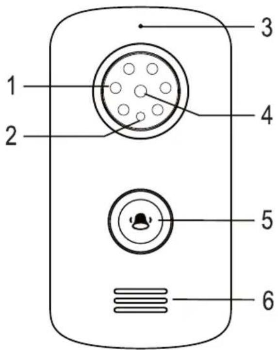
a) Outdoor unit
text_image
1 2 3 4 5 6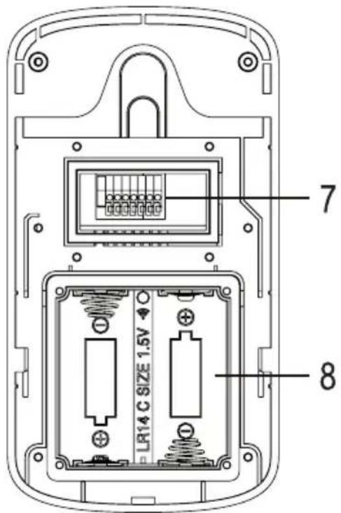
text_image
7 LR14 C SIZE 1.5V 81 6 white LEDs
2 Brightness sensor
3 Microphone
4 Camera
5 Call button
6 Speaker
7 Terminals
8 Battery compartment
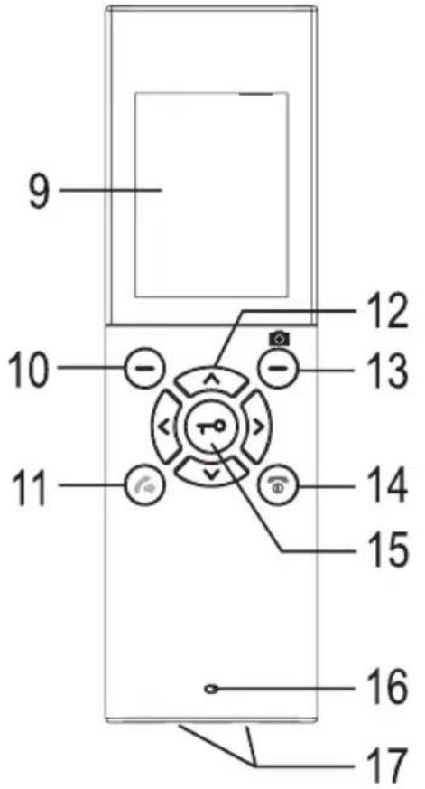
b) Handset
text_image
9 10 11 12 13 14 15 16 17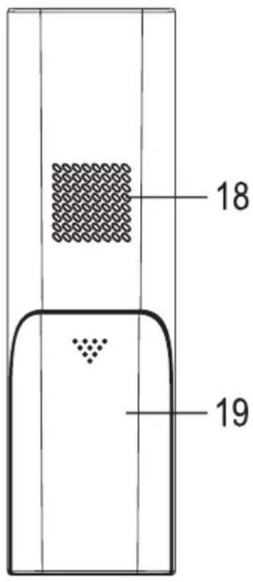
text_image
18 199 Display
10 Left menu button (function depends on the display in the bottom left of the display)
11 Speaker button
12 Arrow keys ∧, and < >
13 Right menu button (function depends on the display in the bottom right of the display)
14 Speaker button
15 Speaker button
16 Microphone
17 Charging contacts
18 Speaker
19 Battery compartment cover
c) Charging station
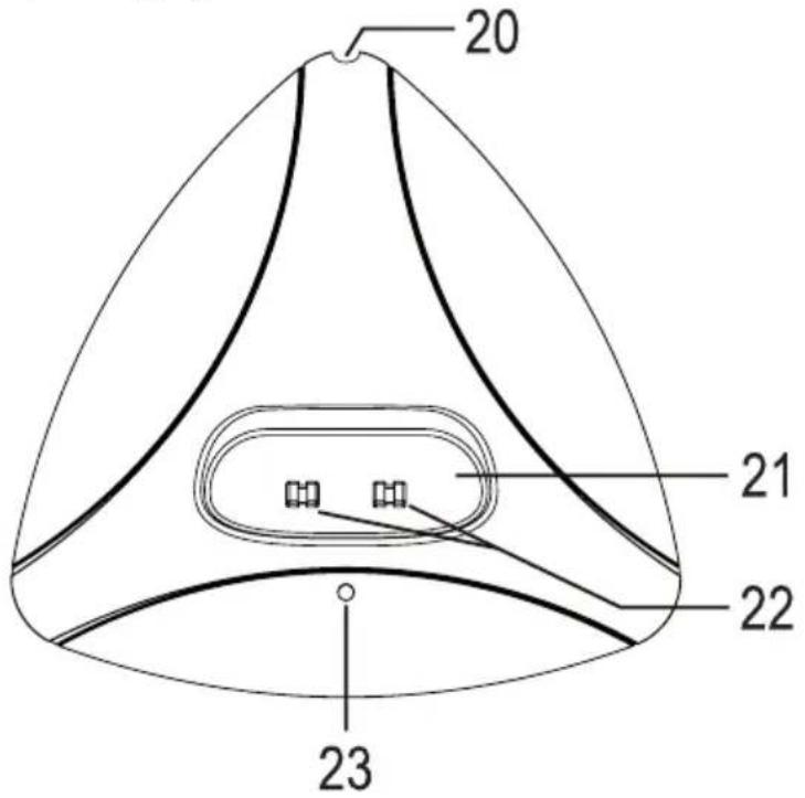
text_image
20 21 22 2320 Opening (for connection cable to the power adapter); the circular socket for connecting the power adapter is located on the underside of the charging station)
21 Opening for handset
22 Charging contacts
23 Power LED
7. Commissioning the handset
a) Insert the battery into the handset
Open the battery compartment on the back of the handset (A) by sliding the battery compartment cover (D) down.
Then insert the supplied Li-Ion rechargeable battery (B) correctly into the battery compartment (C). The contacts of the rechargeable battery must point to the connection contacts in the battery compartment.

If there is a protective strip over the battery contacts or if the battery is in a plastic film, remove it first.
Do not use force when inserting the battery; the battery only fits into the battery compartment in one direction, it can be inserted easily.
Then close the battery compartment, and slide the battery compartment cover (D) back into the handset (A) until it clicks into place.
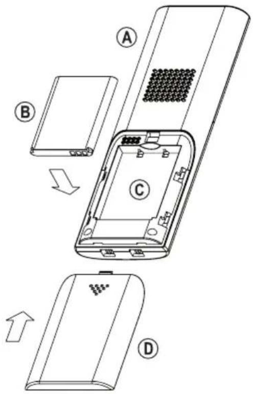
text_image
Diagram of a device's internal structure with labeled parts A, B, C, and D showing exploded and assembled views.b) Connecting the charging station
Connect the circular socket of the supplied power adapter to the socket on the bottom of the charging station.
Route the cable back through the provided cable slot so that it comes out of the opening (20).
If the circular socket and cable are placed correctly, the charging station can be placed flat on the table without the charging station wiggling or tilting.
Place the charging station on a level, stable surface only. Use an overlay to protect valuable furniture surfaces from scratches, dents and discoloration.
Connect the power adapter to a mains socket. The LED (23) will light up.
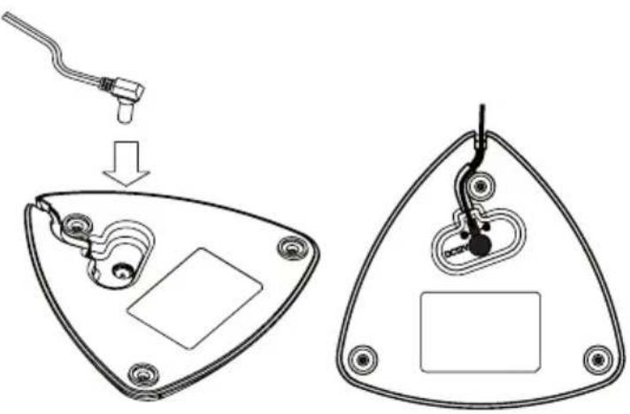
text_image
Diagram showing a device's internal components and assembly, with labeled parts and directional arrows indicating process.c) Plug the handset into the charging station, charge the rechargeable battery
If there is a transparent protective foil on the front of the handset, pull it off carefully.
Place the handset in the charging station. The LED in the button (15) will light up.
The handset only fits into the charging station in one direction. Never use force to insert the handset into the charging station.

The rechargeable battery is not fully charged upon delivery. It must be charged completely by leaving the handset in the charging station for about 5 hours.
Charging a partially charged rechargeable battery is not a problem, the handset can be placed in the charging station at any time.
The integrated charging electronics end the charging process automatically.
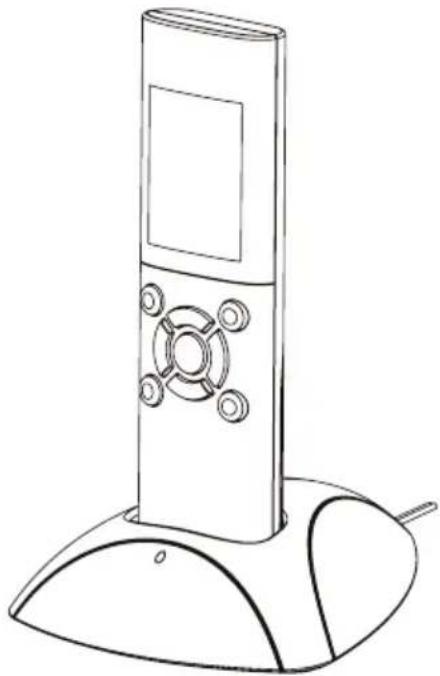
natural_image
Line drawing of a modern remote control tower with a base and antenna (no text or symbols)8. Assembly/connection of the outdoor unit
a) General information
The outdoor unit should be mounted in an area protected from direct rainfall (for example, near the front door under a canopy) so that the visitor stands directly in front of it when pressing the call button. The camera should be mounted at the height of about 150 cm, depending on the environment conditions at the place of installation.

Take care that cables or lines are not damaged while drilling and/or bolting down! The same applies to laying the connection/connection cable (voltage/power supply and door opener) and any necessary masonry work.
The outdoor unit can be powered by an adapter or alternatively by batteries (not included).

You should test the video door intercom system at the future place of installation before you drill the holes for fixed installation and lay the cable.
Mount the outdoor unit only on a stable surface, but not on metal surfaces or near any other electrical/electronic equipment, as this will negatively affect the radio range.
Take care that cables or lines are not damaged while drilling and/or bolting down! The same applies to laying the connection/connection cable and any necessary masonry work.
b) Operation via batteries, insert/change batteries

Important!
If the device is operated by a power supply (and possibly an additional UPS), batteries must not be inserted.
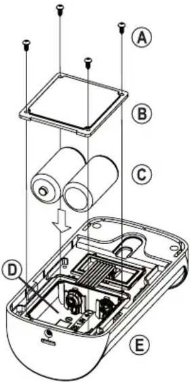
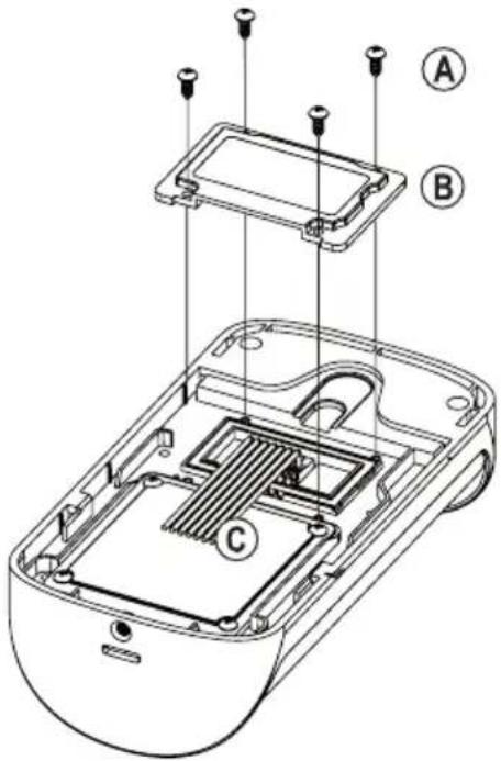
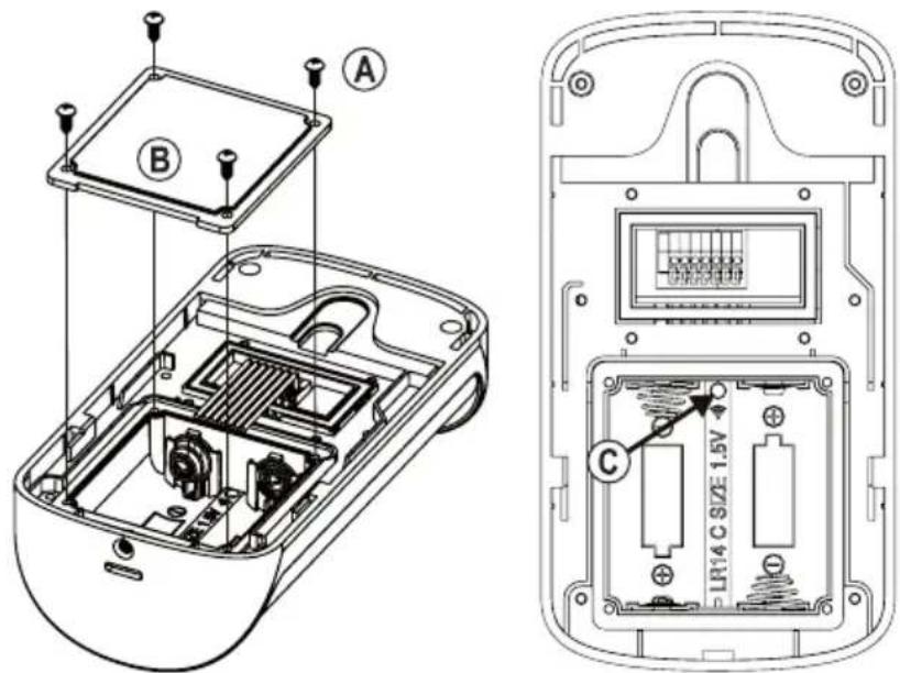
If the outdoor unit (E) must be powered by batteries, first remove the four screws (A) and then remove the square battery compartment cover (B) (note the placement).
Insert two baby/C batteries (C) with the correct polarity into the battery compartment (D); pay attention to the correct polarity (plus/+ and minus/-), see labels on the batteries and in the battery compartment.
Then replace the battery compartment cover (B) and secure it with the previously removed four screws (A). Pay attention to the correct placement of the battery compartment cover.

During battery operation, the power-saving mode is automatically activated. Here, it is not possible to activate the outdoor unit from the handset (monitor function).
However, this can be changed, see chapter 11. c).
text_image
Exploded view diagram of a device showing internal components and labeled parts A through Ec) Wiring diagram

Important!
If the device is operated by a power supply (and possibly an additional UPS), batteries must not be inserted.

The outdoor unit has a potential-free switch contact (contact load capacity, see chapter "Technical data"). Therefore either a "fail-secure" or a "fail-safe" door opener can be connected. Never switch the mains voltage over the connection terminals of the outdoor unit! An electric shock poses a risk to life!
Wiring diagram for "Fail-Secure" door opener: This releases the locking latch only when its operating voltage is applied (common design for front doors).
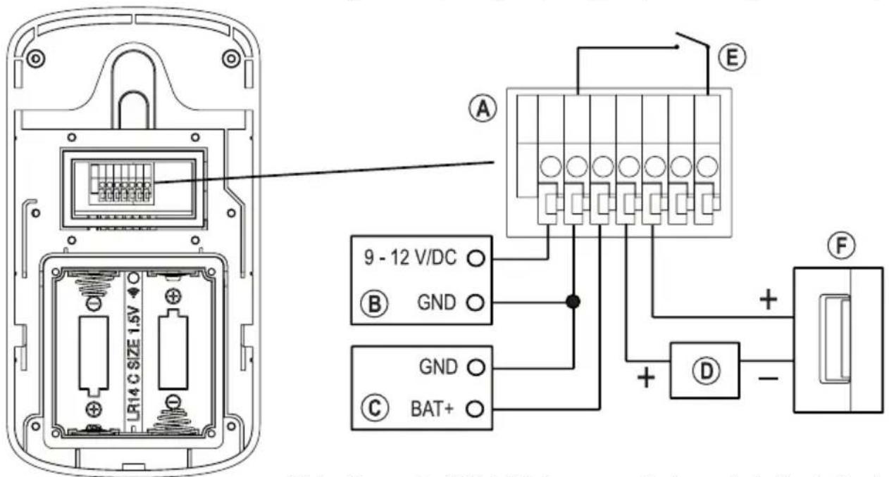
text_image
LR14 C SIZE 1.5V 9 - 12 V/DC GND GND BAT+ E F + - DWiring diagram for "Fail-Safe" door opener: It releases the locking latch only when the operating voltage is absent (rare type, used, for example, for escape route doors, as the door can be opened in the event of a power failure).
A Terminal block
B External power supply (9 - 12 V/DC)
C External UPS (for example from an alarm system, 9 - 12 V/DC)
D Voltage/power supply for the door opener
E Door opener button in the apartment
F Fail-secure door opener (standard for entrance doors)
G Fail-safe door opener (rare, such as for escape route doors)
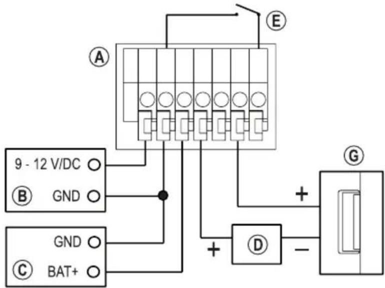
text_image
9 - 12 V/DC GND GND BAT+ A E D + - Gd) Assembly of the outdoor unit
It may be necessary to drill holes at the intended installation position depending on the substrate.

Ensure that you do not damage cables or wires when drilling holes or tightening screws.
adequate sealing at the point where the cable comes out of the wall so that water running down the wall (e.g. when it rains) cannot run along the cable into the wall. Use some silicone for sealing.
First, remove the four screws (A) of the top cover (B) and remove them (note the positions).
Wire the connectors on the back according to the wiring diagram in Chapter 8. c).

Important!
device is operated by a power supply (and possibly an additional UPS), batteries must not be inserted.
Run the cables down. A seal prevents the penetration of moisture.
Replace the cover (B) and secure it with the four screws (A) that were previously removed. Ensure the cover is put back on in the right direction. Only one way is correct (the flattened inside must lie over the cables).
text_image
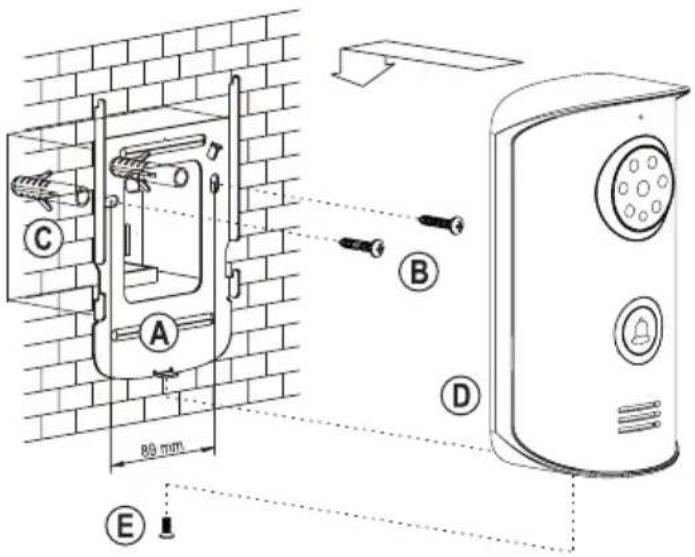
Technical diagram of a device's internal structure with labeled components A, B, and CMount the wall bracket (A) with two suitable screws (B) and, if necessary, dowels (C), as shown in the picture, depending on the condition of the wall.
Place the outdoor unit (D) on the wall bracket (A). Make sure that the connecting cables are not damaged.
Secure the outdoor unit to the wall bracket using the supplied special screw (E), the matching tool (L-key) is included.

If there is a protective film on the camera/LED protective screen, remove it now.
text_image
C A B D 80 mm E9. Setup and operation
a) General information
→ If you have placed the outdoor unit and the handset side by side for test purposes, please note that there may be loud feedback noise from the microphone and speakers.
Such behaviour is normal.
Maintain a distance of several meters between the outdoor unit and the handset to avoid this feedback noise during the test. Alternatively, temporarily apply several layers of duct tape to the microphone openings.
If you have not yet done so, insert the Li-Ion rechargeable battery into the handset. Connect the power adapter to the charging station and the mains voltage. Place the handset in the charging station and charge it. Refer to chapter 7.
If you are not using the outdoor unit with batteries, then switch on the voltage/power supply for the outdoor unit.

Important!
device of the outdoor unit is operated by a power supply (and possibly an additional UPS), do not insert batteries.
b) Switching the handset on/off, standby function
Hold down the button (14) (about 3 seconds) to turn the handset on or off.
At the top right, the rechargeable battery status is displayed with a corresponding icon.
If the ! warning symbol appears in the display, the rechargeable battery is empty. The handset then switches itself off. In this case, fully charge the handset.
→ The time must be set for it to be displayed correctly.
The handset activates standby function if no key is pressed. The display is turned off to save power. If you briefly press any key, the handset emits a short confirmation tone and the display is reactivated.

text_image
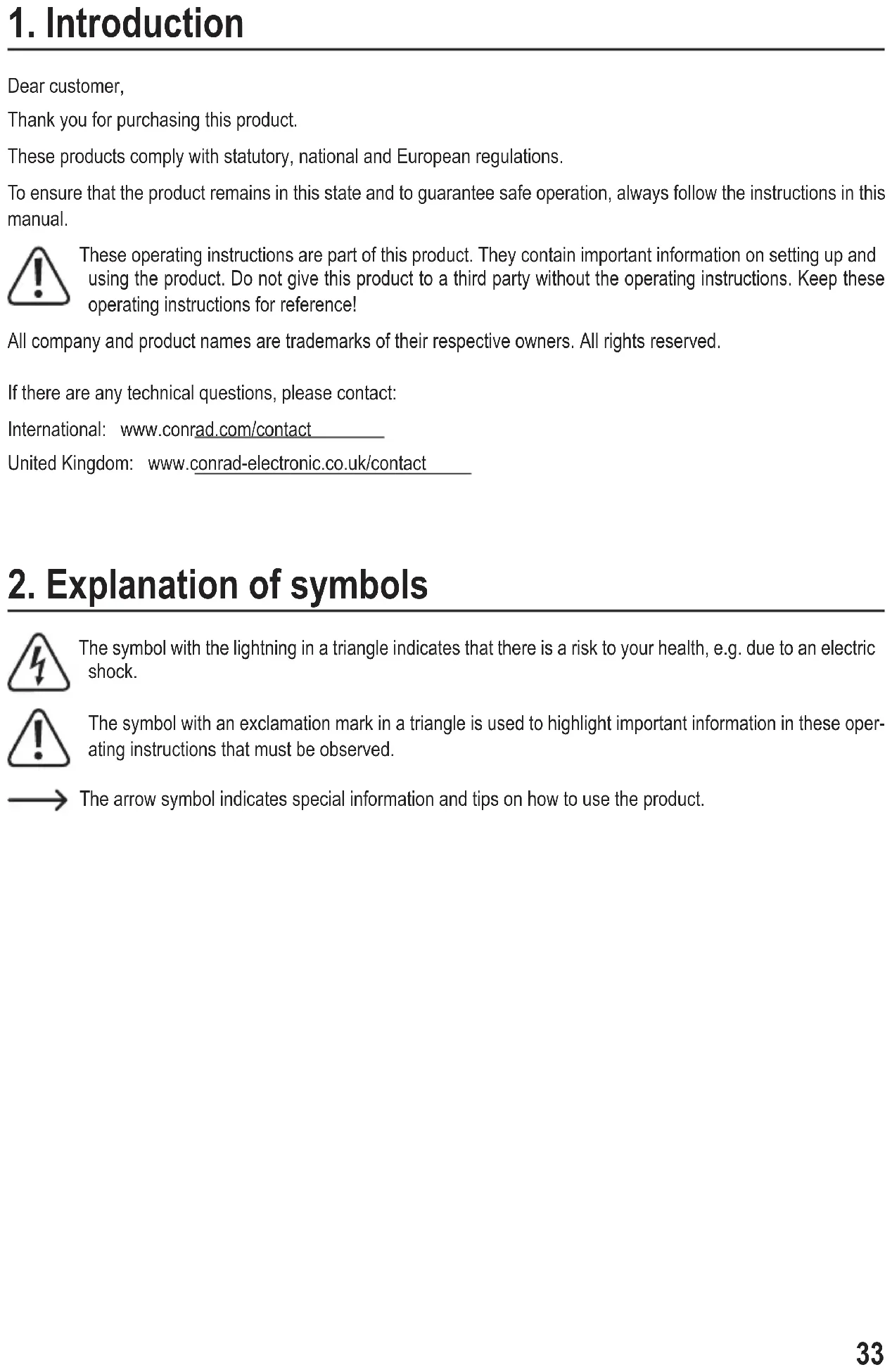
15:36 Menu Monc) Call up and operate the setting menu
Briefly press the left menu button (10) from the normal display (see picture on the right). The setting menu is displayed.
Use and arrow keys to select the various functions.
Confirm the selection with the left menu button (10). You can set /change it later depending on the selected function,
→ For example, in the "Language" function, you can select the menu language for the handset.
The right menu button (13) returns to the normal display.

text_image
15:36 Menu Mon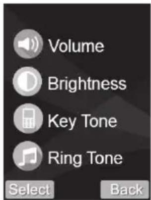
text_image
Volume Brightness Key Tone Ring Tone Select Back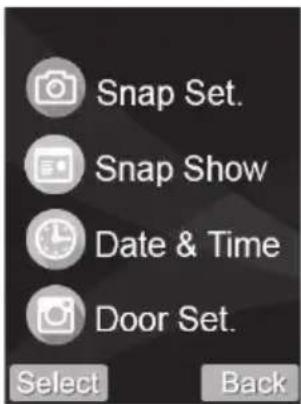
text_image
Snap Set. Snap Show Date & Time Door Set. Select Back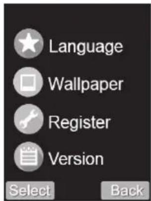
text_image
Language Wallpaper Register Version Select Back
text_image
Default Set. Select BackThe pictures above show the menu functions in English (basic setting of the handset on delivery or after resetting to the basic settings).

Set voice volume, ringtone volume and ringing time
Use for arrow key to select the respective setting.
Use or arrow key to change a setting.
- Playback volume: 9 levels selectable (volume of the speaker on the handset)
• Ring volume: 9 levels selectable (volume of the ringtone on the handset)
• Ring time: Adjustable from 1 - 30 seconds (duration of the ringtone on the handset)
Briefly press the left menu button (10) to save the setting and return to the previous menu. The right menu button (13) can be used to cancel the setting process.
In the normal display, the volume can be adjusted with or arrow key or without having to call up the menu.

Set display brightness
The brightness of the display can be changed in 9 steps with or arrow key.
Briefly press the left menu button (10) to save the setting and return to the previous menu. The right menu button (13) can be used to cancel the setting process.
In the normal display, the brightness can be changed with or arrow key or without having to call up the menu.

Activate/deactivate key confirmation tone
You can turn the key confirmation tone on or off here. If this is switched on, each keystroke is confirmed with a short beep.
Briefly press the left menu button (10) to save the setting and return to the previous menu. The right menu button (13) can be used to cancel the setting process.

Select ringtone
You can switch between three different ringtones using ∧ or ∨ arrow keys. The respective ringtone is automatically played back to check.
Briefly press the left menu button (10) to save the setting and return to the previous menu. The right menu button (13) can be used to cancel the setting process.

Turn automatic photo recording on/off
If automatic photo recording is turned on, an image is stored in the handset every time a visitor presses the bell button on the outdoor unit.
Briefly press the left menu button (10) to save the setting and return to the previous menu. The right menu button (13) can be used to cancel the setting process.
→ During a call between the handset and the outdoor unit, a photo can be taken manually by pressing the right menu button (13).
It is also possible to take a picture while using the monitor function.
The pictures are stored in the handset (up to 100 in total). When the memory is full, the oldest image is automatically overwritten.

View/delete recorded images
Storedpictures can be viewed or deleted here.
If there are pictures in the memory, they can be displayed successively with or arrow key. For each picture, the date and time are displayed. To return to the previous menu, briefly press the right menu button (13) ↩.
If the image displayed should be deleted, press the left menu button (10). A confirmation prompt appears. This is confirmed and the picture is deleted with the left menu button (10). If you press the right menu button (13) instead, the deletion will be cancelled.
To delete all the pictures, press the ⏻ button (15). A confirmation prompt appears. This is confirmed and all pictures will be deleted with the left menu button (10). If you press the right menu button (13) instead, the deletion will be cancelled.
→ Deleted images cannot be recovered.
The images in the handset memory are reretained, even when the rechargeable battery is empty or replaced.

Set the date and time
In this function you can set the date and time for the handset. The setting is mainly required to be able to save the date and time of each picture taken. If you have activated automatic photo taking, you can later see when a visitor rang the door.
With < or > arrow key, you can select the entry position (hours, minutes, year, month and day). The active entry position flashes.
Change the flashing value with ∧ or ∧ or key.
Briefly press the left menu button (10) to save the setting and return to the previous menu. The right menu button (13) can be used to cancel the setting process.
If the battery of the handset is completely empty or if the battery is removed from the handset, the time setting will be lost.

Set duration of the ringing and door opener activation
Use or arrow key to select the respective setting.
Use or arrow key to change a setting.
• Ring time: Adjustable from 1 - 15 seconds
• Duration of door opener Adjustable from 1 - 9 seconds
Briefly press the left menu button (10) to save the setting and return to the previous menu. The right menu button (13) can be used to cancel the setting process.

Select menu language
You can select the desired menu language using or (alternatively or).
Briefly press the left menu button (10) to save the setting and return to the previous menu. The right menu button (13) can be used to cancel the setting process.

Select wallpaper for the display
One of the three different background images can be selected using or arrow keys.
Briefly press the left menu button (10) to save the setting and return to the previous menu. The right menu button (13) can be used to cancel the setting process.

Register the outdoor unit to the handset
With this function, you can register the outdoor unit to the handset.
→ Normally, this process has already been carried out by the manufacturer. If the outdoor unit and the handset do not react to each other, you can carry out the registration process yourself.
Please refer to Chapter 10 for the registration process.

Display the firmware version
After calling the function, the firmware version is displayed. Briefly press the right menu button (13) to return to the previous menu.

Restore basic settings
You can reset all settings to the default here.
→ After resetting, you must re-register the outdoor unit with the handset, see chapter 10.
After calling up the function, a confirmation prompt appears.
You can make a selection (yes or no) using the or arrow keys.
If the settings must be reset to the default settings, select the corresponding display and press the left menu button (10).
To cancel the reset, just press the right menu button (13). The previous menu will be displayed again.
10. Register the outdoor unit to the handset
→ Normally, this process has already been carried out by the manufacturer. If the outdoor unit and the handset do not react to each other, you can carry out the registration process yourself.
The login process is also required if the handset has been reset to the default settings.
Follow the procedure below to log in:
- Put the handset into operation (insert the rechargeable battery and charge it if necessary).
- Put the outdoor unit into operation, if not you have not already done so. This requires the voltage/power supply (either via an external power supply or with two baby/C batteries).
- Test the function of the handset. When you press a key, the display should appear (if necessary, switch on the handset beforehand by holding down the button (14) for approx. three seconds).
- To test the function of the outdoor unit, press the bell button. Normally the handset should register a visitor and the camera image should appear. If this is the case, the outdoor unit is already registered to the handset. The procedure described below is not required.
However, if the outdoor unit only emits a short beep when the bell button is pressed, and a double-beep signal sounds after a few seconds, the outdoor unit has not found a handset. The handset will also not respond to the bell button of the outdoor unit. In this case, follow these further steps.
- If you have already mounted the outdoor unit firmly to the wall, then you must remove it for the registration process. If a sabotage alarm is activated (see chapter 11. e), deactivate it by pressing the button (14) on the handset.
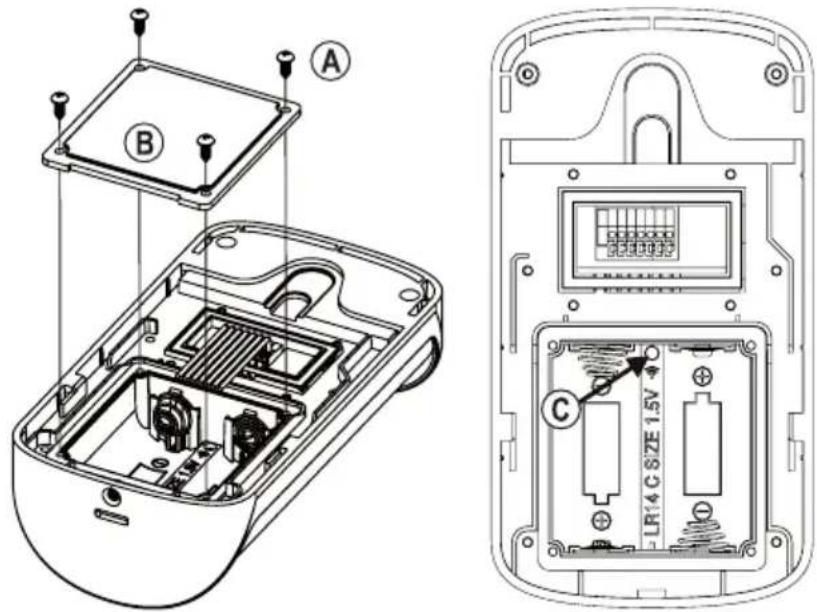
- Open the battery compartment of the outdoor unit. First, remove the four screws (A) and then remove the square battery compartment cover (B) (note the position).
• There is a small button (C) in the battery compartment, see arrow in the right image.
text_image
Technical diagram of a remote control device showing internal components and labeled parts (A, B, C)- Press and hold this button for about three seconds until the outdoor unit emits one beep. In addition, the LED ring around the bell button (on the front of the outdoor unit) flashes. The outdoor unit is now in log-on mode (for about one minute).
- Activate the display on the handset by briefly pressing any key. To display the setting menu, briefly press the left menu button (10).
- Start the function for registering an outdoor unit to the handset, see chapter 9. The symbol for this function can be seen in the picture on the right.

• Use or arrow key to select outdoor unit #1 or #2.
→ Two outdoor units can be registered to each handset. You can thus operate two handsets and two outdoor units (that is, two complete sets), e.g. to equip two of a house's entrance doors with outdoor units.
In such a case, reset both handsets to the default setting and register both outdoor units to both handsets.
- If the memory for outdoor unit #1 or #2 is empty, briefly press the left menu button (10) to start the login process. Cancel the registration process using the right menu button (13).
If the memory is full, a garbage bin symbol will appear in the lower left corner and the memory can be cleared with the left menu button (10). Confirm the following confirmation prompt with the left menu button (10) or cancel the action with the right menu button (13).
When signing in, make sure that the outdoor unit is in log-on mode (the LED ring around the outdoor unit bell button flashes). Otherwise, registration of the outdoor unit is not possible. If necessary, start the log-on mode of the outdoor unit again as described above.
- The handset emits a beep and a bar graph appears in the lower part of the display (search for the signal from the outdoor unit). The registration process can take up to 20 seconds.
- If the outdoor unit is found and logged in, the outdoor unit will beep and the LED ring around the bell button will stop flashing, but will stay lit. On the handset, the display changes back to the time display.
- If you press the doorbell button on the outdoor unit now, a visitor should be reported on the handset and the camera image should appear. The outdoor unit is registered on the handset.
If this does not occur, start the registration process again.
→ Make sure (as described above) that the outdoor unit is in log-on mode (the LED ring around the outdoor unit bell flashes). The registration mode ends automatically after approximately one minute (LED ring stops flashing).
During this period (LED ring flashing), the log-on mode must be called up and started on the handset!
- Close the battery compartment again and then attach the outdoor unit to the wall bracket.
11. Operation
a) Visitor rings at the outdoor unit
- When a visitor presses the doorbell button on the outdoor unit, standby mode ends and the camera in the outdoor unit turns on. When the ambient brightness is low, the white LEDs on the outdoor unit are automatically activated. The camera image appears on the handset display. In addition, a ring tone melody will sound from the handset's speaker as well as a bell signal on the outdoor unit (for up to 30 seconds).
- Press the speaker button (11) to talk to the visitor.
→ After about 45 seconds, the handset automatically switches back to standby mode.
Alternatively, you can reject the visitor with the button (14); the ring tone melody stops, the camera image disappears and the handset display shows the time of day again.
• To take a picture of the visitor during the conversation, briefly press the right menu button (13).
- While the image of the camera of the outdoor unit is shown in the display, press the ⏻ button (15) to activate the door opener (activation time can be changed in the handset setting menu, see chapter 9).
- If you want to end the call with the visitor, press the Ⓤ button (14). The handset display shows the time again; the display goes off automatically after a while.
b) Activate the outdoor unit from the handset (monitor function)
→ This feature is not available by default when battery-powered.
If desired, you can change this basic setting (see chapter 11. E). However, this results in shorter battery life.
- If the handset is in standby mode (no indication in the display), briefly press any key. The display of the handset is then activated (time display appears).
• The camera image appears If you briefly press the right menu button (13).
• To take a picture of the visitor, briefly press the right menu button (13). - Press the speaker button (11) to talk to the visitor.
→ After about 45 seconds, the handset automatically switches back to standby mode.
- While the image of the camera of the outdoor unit is shown in the display, press the ⏻ button (15) to activate the door opener (activation time can be changed in the handset setting menu, see chapter 9).
- If you want to end the call, press the ⏻ button (14). The handset display shows the time again; the display goes off automatically after a while.
c) Activate the monitor function during battery operation
The outdoor unit can be activated by default in the handset, see chapter 11. C)

This feature is not available by default when battery-powered. However, you can enable it as described below. However, this results in shorter battery life.
When operating via an external power supply, the following setting has no effect!
- If you have already mounted the outdoor unit firmly to the wall, you will need to remove it to change the setting. If a sabotage alarm is activated (see chapter 11. e), deactivate it by pressing the button (14) on the handset.
- Open the battery compartment of the outdoor unit. First, remove the four screws (A) and then remove the square battery compartment cover (B) (note the position).
• There is a small button (C) in the battery compartment, see arrow in the right image.
text_image
Technical diagram of a remote control device showing internal components and labeled parts (A, B, C)Switch on the monitor function during battery operation:
- Press and hold the button in the battery compartment for about three seconds until the outdoor unit emits a beep (this indicates that the monitor function is off during the battery operation).
- Press and hold this button again for about three seconds until the outdoor unit emits three short beeps. The monitor function is switched on during battery operation.
- Close the battery compartment again and then attach the outdoor unit to the wall bracket.
Switch off the monitor function during battery operation:
- Press and hold the button in the battery compartment for about three seconds until the outdoor unit emits three beeps (this indicates that the monitor function is switched on during battery operation).
- Press and hold this button again for about three seconds until the outdoor unit emits one short beep. The monitor function is switched off during battery operation.
- Close the battery compartment again and then attach the outdoor unit to the wall bracket.
d) Operating the door opener
→ Activating a door opener is only possible if a camera image is shown on the display of the handset.
Proceed as described in chapter 11. a) or 11. b).
e) Sabotage alarm when removing the outdoor unit
If the outdoor unit is removed from the wall mount during the operation, both the outdoor unit and the handset speaker will sound an alarm. The camera image appears on the handset display.
→ The alarm can last for up to five minutes.
To take a picture of the visitor, briefly press the right menu button (13).
Press the speaker button (11) to activate a voice connection or the button (14) to deactivate the alarm.
f) Activate the door opener via push button
If an external push button is connected to the outdoor unit (see connection diagram in chapter 8. c), the door opener can be activated without the need of the handset.
12. Troubleshooting
No picture, no sound
- Turn on the handset.
- Check that the battery is correctly inserted into the handset. Charge the handset.
- Check the voltage/power supply of the outdoor unit.
- If using batteries to operate the outdoor unit, check that they are inserted correctly. If necessary, replace them with new batteries.
Door opener does not work
- Check the door opener of the outdoor unit is wired properly. As the switching output of the outdoor unit is potential-free, you need a separate voltage/power supply for the door opener, see chapter 8. c).
- The outdoor unit has a switchover contact for the door opener. Depending on the door opener used, the connection must be made accordingly, see chapter 8. c).
- For activation of the door opener, the camera image must be displayed on the handset (visitor has rung the outdoor unit or you activate the monitor function).
Flickering picture on the monitor of the indoor unit
• This is caused by backlight or reflecting objects in the area of the outdoor unit camera.
The monitor function cannot be activated on the handset
- If the outdoor unit is battery-powered, the monitor function is disabled by default to save power and to increase battery life. However, it can be turned on when using batteries. Please refer to chapter 11. c).
The handset does not respond to the bell button being pressed on the outdoor unit
- Indicate the outdoor unit on the handset, see chapter 10.
• The distance between the outdoor unit and the handset is too large. - The reception conditions are unfavourable, e.g. thick walls or metal doors near the outdoor unit or handset. Metal-coated insulation in walls also has a negative impact on operation.
Operating time of the handset is too short
- Charge the rechargeable battery. Insert the handset correctly into the charging station.
- Check whether the LED on the front of the charging station is lit (charging station is connected to the mains adapter and ready for use).
The doorbell button on the outdoor unit is not lit
- The LED ring around the outside of the bell button only lights up if the outdoor unit is operated via an external power supply unit. This is not possible with battery operation.
13. Declaration of Conformity (DOC)
Conrad Electronic SE, Klaus-Conrad-Straße 1, D-92240 Hirschau, hereby declares that this product conforms to Directive 2014/53/EU.
→ Click on the following link to read the full text of the EU Declaration of Conformity:
www.conrad.com/downloads
Select a language by clicking on the corresponding flag symbol, and then enter the product order number in the search box. The EU Declaration of Conformity is available for download in PDF format.
14. Disposal
a) Product

Electronic devices are recyclable waste and must not be disposed of in the household waste. At the end of its service life, dispose of the product according to the relevant statutory regulations.
Remove any inserted (rechargeable) batteries and dispose of them separately from the product.
b) (Rechargeable) batteries
You as the end user are required by law (Battery Ordinance) to return all used batteries/rechargeable batteries. Disposing of them in the household waste is prohibited.

Contaminated (rechargeable) batteries are labelled with this symbol to indicate that disposal in the domestic waste is forbidden. The designations for the heavy metals involved are: Cd = Cadmium, Hg = Mercury, Pb = Lead (name on (rechargeable) batteries, e.g. below the trash icon on the left).
Used (rechargeable) batteries can be returned to collection points in your municipality, our stores or wherever (rechargeable) batteries are sold.
You thus fulfil your statutory obligations and contribute to environmental protection.
15. Care and cleaning
This product does not require maintenance. Repair or maintenance work must be carried out by a technician or a specialist repair centre. Under no circumstances should you service any of the components in the interior of the product.
A dry, soft and clean cloth is sufficient for cleaning the exterior.
Never use aggressive detergents, rubbing alcohol or other chemical solutions, as these may damage the housing or cause the product to malfunction.
16. Technical data
a) General information
Frequency range 2.400 - 2.4835 GHz
Transmission power....19 dBm (typ.)
Range up to 500 m (in an openarea)
b) Handset
Voltage/Power rechargeable .....Li-Ion battery, 3.7V, 1100 mAh
Display resolution 320 x 240
Bell melodies....3 (switchable)
Internal memory for images......yes (max 100)
Ambient conditions.....temperature -10 °C to +40 °C, 20% to 90% relative humidity, non-condensing
Dimensions....171 x 51 x 19 mm (W x D x H)
Weight ....approx. 130g (including the rechargeable battery)
c) Outdoor unit
Voltage/power supply ......via the external power supply 9 - 12 V/DC, max. 200 mA or with two baby/C batteries
Battery life....approx. 2 - 3 months with 5 conversations/activations per day
→ We recommend using an external power supply (not included).
Image sensor.....CMOS
Effective resolution....640 x 480 (horizontal x vertical)
Focal length....2.33 mm
Aperture angle....72° horizontal, 95° vertical
Operation in the dark.....yes, with six white LEDs (automatically activated at night)
Relay contact load for door opener ....potential-free changeover contact (NO/NC), max. 12 V/DC, max. 1 A
Protection class IP55
Ambient conditions.....temperature -20 °C to +55 °C
Mounting/operating location ....protected outdoor area
Dimensions....161 x 87 x 53 mm (H x W x D)
Weight .....approx. 230 g
d) Power adapter
Operating voltage 100 - 240 V/AC, 50/60 Hz
Output....12 V/DC, 0.5 A
e) Charging station
Voltage/power supply 12 V/DC, 0.5 A
Ambient conditions ......temperature -10 °C to +40 °C, 20% to 90% relative humidity, non-condensing
Dimensions....123 x 119 x 37.5 mm (W x D x H)
Weight ....approx. 454g (including the weather protection)
Page
France (email) : technique@conrad-france.fr
d) Station de charge
text_image
Diagram of a device's internal structure and assembly, labeled with components A, B, C, D and directional arrows indicating assembly steps.b) Raccordement de la station de charge
natural_image
Line drawing of a remote control tower with a base and antenna (no text or symbols)text_image
Technical diagram of a device's internal components with labeled parts A through Etext_image
Technical diagram of a mobile phone casing with labeled components A, B, and Ctext_image
Volume Brightness Key Tone Ring Tone Select Back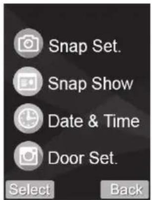
text_image
Snap Set. Snap Show Date & Time Door Set. Select Back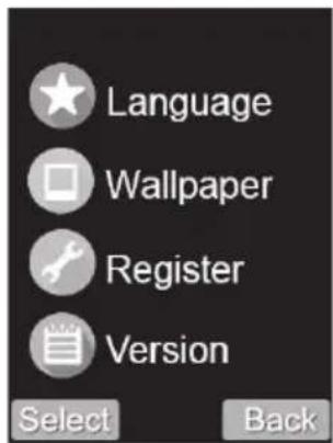
text_image
Language Wallpaper Register Version Select Back
text_image
Default Set. Select Backtext_image
Technical diagram of a mobile phone casing with labeled components A and B, showing internal circuitry and mounting points.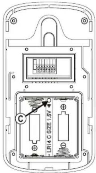
text_image
C LR14 C SIZE 1.5Vtext_image
Technical diagram of a mobile phone casing with labeled components A and B, showing internal circuitry and mounting points.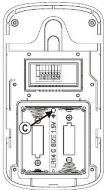
text_image
C LR14 C SIZE 1.5Vwww.conrad.com/downloads
Tension/alimentation....12 V/CC, 0,5 A
text_image
Diagram of a device's internal structure with labeled parts A, B, C, and D showing exploded and assembled views.text_image
Diagram showing a device's internal components and assembly, with labeled parts and directional arrows indicating process steps.natural_image
Line drawing of a mobile phone tower with control panel and base mount (no text or symbols)text_image
Technical diagram of a device's internal components with labeled parts A through Ec) Aansluitschema

Belangrijk!
text_image
Technical diagram of a mobile phone casing with labeled components A, B, and Ctext_image
Volume Brightness Key Tone Ring Tone Select Back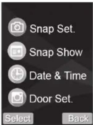
text_image
Snap Set. Snap Show Date & Time Door Set. Select Back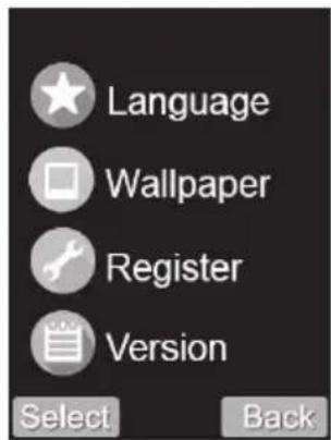
text_image
Language Wallpaper Register Version Select Back
text_image
Default Set. Select Backtext_image
Technical diagram of a remote control device showing internal components and labeled parts (A, B, C)text_image
Technical diagram of a device's internal structure with labeled components A and B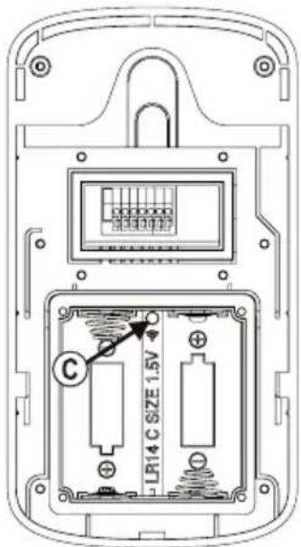
text_image
LR14 C SIZE 1.5V Cwww.conrad.com/downloads
GB This is a publication by Conrad Electronic SE, Klaus-Conrad-Str. 1, D-92240 Hirschau (www.conrad.com).
All rights including translation reserved. Reproduction by any method, e.g. photocopy, microfilming, or the capture in electronic data processing systems require the prior written approval by the editor. Reprinting, also in part, is prohibited. This publication represent the technical status at the time of printing.
Copyright 2018 by Conrad Electronic SE.
Copyright 2018 by Conrad Electronic SE.
Copyright 2018 by Conrad Electronic SE.