AOF 1100 - Milling machine Alpha Tools - Free user manual and instructions
Find the device manual for free AOF 1100 Alpha Tools in PDF.

| Product type | Router (hand milling machine) for wood and plastics |
| Brand | Alpha Tools |
| Model | AOF 1100 |
| Power supply | 230 V~ 50 Hz |
| Power consumption | 1020 W |
| No-load speed | 11,000 - 31,000 rpm (variable) |
| Lifting height (max cutting depth) | 40 mm |
| Collets | ∅ 8 mm and ∅ 6 mm |
| Max bit diameter for profiling | ∅ 40 mm |
| Weight | 3.3 kg |
| Sound pressure level (LWA) | 87.9 dB(A) |
| Sound power level (LPA) | 100.9 dB(A) |
| Vibration (aw) | 2.7 m/s² |
| Protection class | II (double insulation) |
| Spindle lock | Yes, for changing the bit |
| Speed regulator | Electronic, setting wheel |
| Depth stop | Yes, with graduated scale |
| Parallel guide | Included, for straight guidance |
| Copying pin | Included, for copying patterns |
| Guide bushing | ∅ 18 mm, included for template work |
| Dust extraction tube | ∅ 36 mm inner diameter, connection for vacuum cleaner |
| Maintenance | Clean ventilation slots with compressed air |
| Warranty | 5 years (material/manufacturing defects) |
Frequently Asked Questions - AOF 1100 Alpha Tools
User questions about AOF 1100 Alpha Tools
0 question about this device. Answer the ones you know or ask your own.
Ask a new question about this device
Download the instructions for your Milling machine in PDF format for free! Find your manual AOF 1100 - Alpha Tools and take your electronic device back in hand. On this page are published all the documents necessary for the use of your device. AOF 1100 by Alpha Tools.
USER MANUAL AOF 1100 Alpha Tools
natural_image
Circular icon with a white headset silhouette on black background, enclosed in a white border (no text or symbols)
natural_image
Simple line drawing of a person's head wearing glasses, enclosed in a circle (no text or symbols)
natural_image
Black and white icon of a person wearing a gas mask and cap, enclosed in a circle (no text or symbols)⑭ 4 -6
GB 7-9
⑤ 10 - 12
© 13 - 15
⑤ 16 - 18
DK 19 - 21
⑤ 22 - 24
⑤ 25 - 27
⑧ 28 - 30
HR 31 - 33
FIN 34 - 36
TR 37 - 39
1
text_image
Labeled diagram of a power tool with numbered parts including motor, cutting board, and wrench2
text_image
Labeled diagram of a mechanical power supply with numbered parts for identificationD
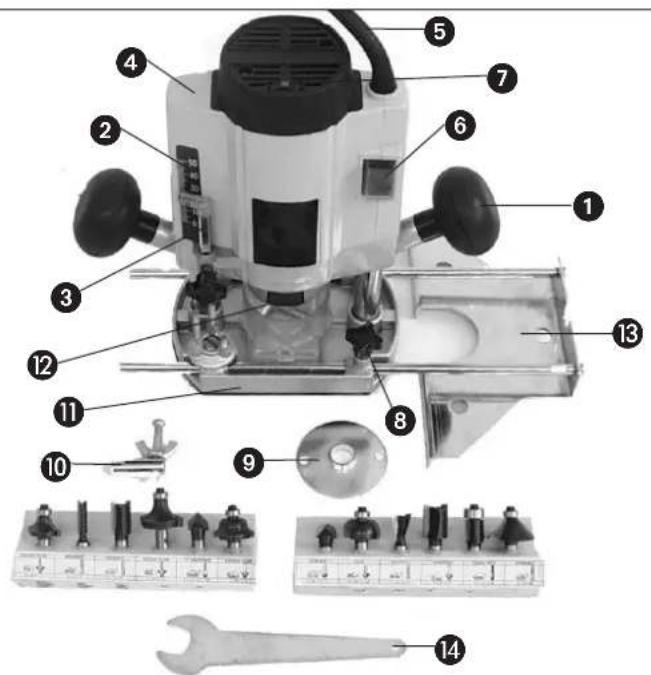
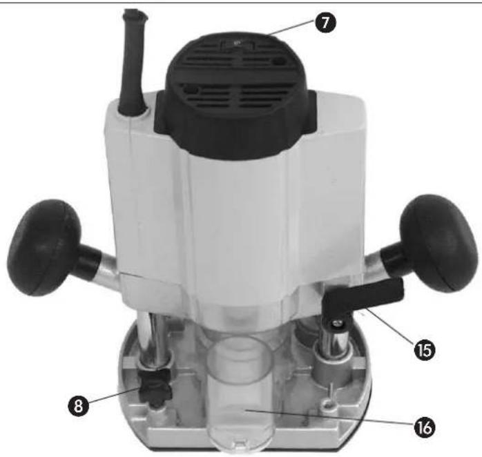
1. Description of the machine (Fig. 1 and 2)
1 Handle
2 Scale
3 Depth stop
4 Motor housing
5 Mains cable
6 ON/OFF switch
7 Speed selector
8 Thumscrew
9 Guide bush ∅ 18
10 Trammel point
11 Routing base
12 Spindle catch
13 Parallel stop
14 Spanner size 19
15 Clamping handle
16 Extractor socket internal ∅ 36
2. Technical data
Voltage: 230 V - 50 Hz
Power consumption: 1020 W
Idle speed: 11.000 - 31.000 rpm
Stroke/routing depth: 40 mm
Collet: ∅ 8 and ∅ 6 mm
For moulding cutters: max. ∅ 40 mm
Safety insulated II / ☐
Weight: 3.3 kg
Sound pressure level LWA: 87,9 dB(A)
Sound power level LPA 100,9 dB(A)
Vibration aw: 2,7 m/s ^4
3. Intended use
The router is ideal for the processing of wood and plastic, for the removal of knots, for the cutting of grooves and recesses, and for the copying of curves and lettering etc.
It is prohibited to use the router to process metal, stone and similar materials.
The machine is to be used only for its intended purpose.
Any use beyond its intended purpose is a case of mis-use. Liability for damage or injury resulting from such a case of mis-use shall rest with the user or operator and not with the manufacturer.
4. Important information
Please read the operating instructions carefully and note their contents. Use these operating instructions to acquaint yourself with the machine, its proper use and essential safety precautions. Keep the operating instructions together with the router.
Safety information
● Make sure the machine is switched off before inserting the plug in the socket-outlet.
- Clamp the workpiece securely to prevent it from slipping.
● Always run the cable away from the back of the machine.
● Always remove the plug from the socket-outlet before doing any work on the machine
- Check that the cutter is fitted securely before starting up the machine.
● Always make sure of your footing while using the machine.
- The direction of routing must always be opposite to the cutter's direction of rotation.
- Do not feed the cutter into the workpiece until it is running.
● Always guide the router with both hands.
- Never exceed the maximum speed specified for the cutter.
- Make allowance for the machine's reaction torque, particularly if the cutter jams.
- When you are finished, allow the machine to glide back into starting position.
- Use only properly ground cutters.
● Mount the cutter with friction locking.
- Depending on the material, deeper cuts should be performed in several passes.
- The level of noise at the workplace may exceed 85 dB(A). In this case you will need to introduce noise protection measures for the user. The noise produced by this electric tool was measured in accordance with ISO 3744, NFS 31-031 (84/637/EEC).
● Vibration emission was measured in accordance with ISO 8662-8.
5. Prior to operation
● Before starting the router, make sure that all its guards and safety devices are properly fitted.
- Before connecting up the router, make sure that your power supply complies with the data on the machine's rating plate.
GB
6. Assembly and operation Important!
Pull out the power plug before fitting any parts or making any adjustments.
A.) Fitting the extractor socket (Fig. 3)
Important!
For the sake of your health, always use a dust extractor.
Use the two countersunk head screws (a) to fasten the extractor socket (16) securely to the routing base (11).
The extractor socket is suitable for dust extractors with a suction hose diameter of 36 mm.
B.) Fitting the parallel stop (Fig. 4)
- Insert the guide shaft (a) of the parallel stop (13) in the holes (b) of the routing base (11).
- Adjust the parallel stop (13) to the required distance and clamp it in place with the thumb screws (8).
C.) Fitting the trammel point (Fig. 5)
- Push the trammel point (10) onto the guide shaft (a) of the parallel stop (13) and fasten it in place with the thumb screw (8).
- Place the trammel point against the material.
- Set the required radius by adjusting the parallel stop (13) and fixing it in place with the two thumb screws.
- Switch on the machine.
● After releasing the clamping handle (15), lower the machine slowly as far as the stop.
● Cut grooves, shoulders, etc. at a steady rate of feed, holding the machine with both hands. - When finished, raise the machine again.
- Switch off the machine.
D.) Fitting the guide bush (Fig. 6/7/8)
- Use the two countersunk head screws (f) to fasten the guide bush (9) to the routing base (11).
● The template (c) is traced with the guide ring (b) of the guide bush (9). - To obtain an exact copy, the workpiece (d) must be bigger by an amount equal to the difference between the 'outer edge of the guide ring' and the 'outer edge of the cutter' (e).
E.) Fitting the cutter (Fig. 9)
Important: Pull out the power plug!
● Changing the cutter is easy with the spindle catch.
- Press the spindle catch (12) and get the spindle to latch in place.
- Slacken the union nut with the open-ended span ner.
- Change the cutter and tighten the union nut with the open-ended spanner.
Important: Make sure that all adjustment and assembly tools are removed before starting the machine.
- Dismantle the cutter in reverse order.
F.) Adjusting the depth of cut (Fig. 10)
- Place the machine on the workpiece.
- Undo the thumb screw (a) and the clamping handle (15).
● Lower the machine slowly until the cutter touches the workpiece.
● Tighten the clamping handle (15). - Set the depth stop (3) to the required routing depth as indicated by the scale (5) and fix in place with the thumb screw (a).
- Press the ON/OFF switch (6) to switch on the machine.
- Use the speed selector (7) to set the required cutter speed.
- Release the clamping handle (15) again and lower the cutter to perform the routing job.
- When you are finished with your work, return the machine to starting position.
Routing speed depends on the material to be cut, the rate of feed, and the cutter being used.
G.) Routing direction (Fig. 11)
The direction of routing must always be opposite to the cutter's direction of rotation. Otherwise there is a risk of injury from back kick.
H.) Moulding and edge-cutting (Fig. 12)
- It is also possible to use special cutters with a guide ring for moulding (a) and edge-cutting (b) jobs.
● Fit the cutter.
● Feed the machine carefully up to the workpiece. - Move the guide pin or ball race (c) along the work piece, applying light pressure.
Important:
● Depending on the material, deeper cuts should be performed in several passes.
● Hold the router with both hands on all cutting jobs.
7. Maintenance
- Keep the ventilation slits in the motor housing clean and clear at all times. Use compressed air to remove any deposits from the slits.
F
Eschenstraße 6 · D-94405 Landau/Isar (Germany)
Technical changes subject to change
The guarantee period begins on the sales date and is valid for 5 years.
Responsibility is assumed for faulty construction or material or functional defects.
Any necessary replacement parts an necessary repair work are free of charge.
We do not assume responsibility for consequential damage.
Your customer service partner
DK GARANTIBEVIS
S.C. A Ap. 9 Sector 1
RO 75 121 Bucharest
Tel. 021 4104800, Fax 021 4103568
©CZ Poker Plus S.R.O.
Areal Vu Bechovice
Budava 10B
CZ-19011 Praha - Bechovice 911
Tel.+Fax 02579 10204
YU MP Trading d.o.o.
Cika Ljubina 8/IV
YU 11000 Beograd
GR An. Mavrofidopoulos S.A.
Technical & Commercial company
12, Papastratou & Asklipiou Str.
GR 18545 Piräus
Tel 0210 4136155, Fax 0210 4137692
RUS Bermas
Altufyevskoye shosse, 2A
RUS 127273 Moscowi
Tel 095 3639580, Fax 095 3639581