
WF18DSL - Screwdriver HiKOKI - Free user manual and instructions
Find the device manual for free WF18DSL HiKOKI in PDF.

| Product Type | Automatic screw feeder battery screwdriver |
| Brand | HiKOKI |
| Model | WF18DSL |
| No-load speed | 4200 min⁻¹ |
| Compatible screw dimensions | Diameter 4 mm, length 25 – 41 mm |
| Bit shank | 6.35 mm Hex |
| Battery | Lithium-ion 18 V, model BSL1840 (4.0 Ah, 10 cells) |
| Weight | 1.9 – 2.5 kg (depending on battery) |
| Compatible charger | UC18YRSL / UC18YFSL, voltage 14.4 – 18 V |
| Included accessories | Screw feeding attachment, Phillips bit No. 2 (×3), strip (×3), plastic case, battery cover (×2) |
| Main applications | Screwing into interior plaster walls |
| Rotation direction | Reversing switch (clockwise / counterclockwise) |
| Adjustments | Screw length (28 – 41 mm) and screw depth |
| Automatic feeding function | Screw strip fed automatically during screwdriving |
| Battery indicator | Residual power indicator light |
| Belt hook | Yes, for hanging on belt |
| Sound level | Power 91 dB(A), pressure 80 dB(A), uncertainty 3 dB(A) |
| Vibrations (no-load) | 0.8 m/s² (uncertainty 1.5 m/s²) |
| Routine maintenance | External cleaning with dry or soapy cloth, regular inspection of fixing screws, replacement of carbon brushes |
| Charging temperature | 0 – 40 °C (ideal 20 – 25 °C) |
Frequently Asked Questions - WF18DSL HiKOKI
User questions about WF18DSL HiKOKI
0 question about this device. Answer the ones you know or ask your own.
Ask a new question about this device
Download the instructions for your Screwdriver in PDF format for free! Find your manual WF18DSL - HiKOKI and take your electronic device back in hand. On this page are published all the documents necessary for the use of your device. WF18DSL by HiKOKI.
USER MANUAL WF18DSL HiKOKI
natural_image
Technical line drawing of a mechanical device with multiple pins and a handle (no text or symbols)Read through carefully and understand these instructions before use. Diese Anleitung vor Benutzung des Werkzeugs sorgfältig durchlesen und verstehen. Lire soigneusement et bien assimiler ces instructions avant usage. Prima dell'uso leggere attentamente e comprendere queste instruzioni. Deze gebruiksaanwijzing s.v.p. voor gebruik zorgvuldig doorlezen. Leer cuidadosamente y comprender estas instrucciones antes del uso. Antes de usar, leia com cuidado para assimilar estas instruções. Διαβάστε προσεκτικά και κατανοήσετε αυτές τις οδηγίες πριν τη χρήση.
Handling instructions Bedienungsanleitung Mode d'emploi Istruzioni per l'uso Gebruiksaanwijzing Instrucciones de manejo Instruções de uso Οδηγίες χειρισμού
1

2

3


4

5


6

7

8

9 10


11 12


13 14


15 16
natural_image
Line drawing of a hand holding a handheld device with a spring-like tool inserted (no text or symbols)
17 18


19 20


21 22


23 24


natural_image
Line drawing of a mechanical tool with a knob and handle (no text or symbols)25
| English Deutsch Français Italiano | ||||
| 1 | Rechargeable battery | Aufladbare Batterie | Batterie rechargeable | Batteria ricaricabile |
| 2 | Latch Verriegelung Taquet | Fermo | ||
| 3 | Battery cover Akkuabdeckung | Couvercle de la batterie | Coperchio della batteria | |
| 4 | Terminal Anschluss Borne | Terminale | ||
| 5 | Ventilator | Lüfter | Ventilateur | Ventola |
| 6 | Push | Drücken | Pousser | Premere |
| 7 | Pull out | Herausziehen | Tirer vers l'extérieur | Estrarre |
| 8 | Handle | Handgriff | Poignée | Impugnatura |
| 9 | Charger | Ladegerät | Chargeur | Caricatore |
| 10 | Charging time indicator lamp | Ladezeit-Kontrollleuchte | Témoin lumineux du temps de chargement | Spia luminosa del tempo di ricarica |
| 11 | Trigger switch | Trigger | Déclencheur | Interruttore |
| 12 | Selector button | Wählhebel | Sélecteur | Selettore |
| 13 | (R) and (L) marks | (R) und (L) Zeichen | Indices (R) et (L) | Segno (R), (L) |
| 14 | Guide block | Führungsblock | Guide | Blocco guida |
| 15 | Arrow mark | Pfeilmarkierung | Flèche | Segno freccia |
| 16 | Lever | Hebel | Levier | Leva |
| 17 | Stopper | Anschlag | Cran d'arrêt | Fermo |
| 18 | Slider | Schieber | Glissière | Corsoio |
| 19 | The tip of a bit | Bitspitze | L'embout d'une pointe | La punta di una lama |
| 20 | Slider case | Schiebergehäuse | Boîtier coulissant | Parte scorrevole |
| 21 | Depth adjuster knob | Einschraubtiefeneinstellknopf | Bouton de réglage de la profondeur | Manopola di regolazione della profondità |
| 22 | Belt guide | Gürtelführung | Guide du ruban | Guida per il nastro |
| 23 | Collated screw strips | Gürtelschrauben | Ruban de vis | Nastro portaviti |
| 24 | Set on screw forward | Eine Schraube vorsetzen | Reglage d'une vis vers l'avant | Disporre una vite avanti |
| 25 | Screw in position | Einschraubpositon | Vis en position | Vite in posizione |
| 26 | 1 screw forward | 1 Schraube vorgesetzt | 1 vis vers l'avant | 1 vite avanti |
| 27 | Release button | Freigabetaste | Touche de libération | Tasto di lasciare |
| 28 | Screw feed attachment | Schraubenzuführung | Accessoire d'alimentation de vis | Dispositivo di avanzamento viti |
| 29 | Driver bit No.2 (136L) | Schraubenzieher Bit Nr.2 (136L) | Lame de tournevis No.2 (136L) | Punta aviitatrice n.2 (136L) |
| 30 | Socket hexagonal hole | Sechskantaufnahme | Orifice hexagonal de la douille | Foro esagonale presa |
| 31 | Guide sleeve | Fuhrungsbuchse | Manchon de guidage | Manicotto de guida |
| 32 | Wall | Wand | Mur | Parete |
| 33 | Screw | Schraube | Vis | Vite |
| 34 | Guide to prevent damage to wall | Wandschutzführung | Guide pour éviter d'endommager le mur | Guida per prevenire danneggiamento al muro |
| 35 | 15 mm over | 15 mm Überstand | 15 mm au dessus | oltre 15 mm |
| 36 | Sheet | Vorsatz | Feuillard | Foglio |
| 37 | Protrusion | Vorsprung | Protubérance | Parte sporgente |
| 38 | Screw | Schraube | Vis | Vite |
| 39 | Hook | Haken | Crochet | Gancio |
| 40 | Groove | Nut | Gorge | Scanalatura |
| 41 | Remaining battery indicator switch | Ladezustand-Anzeigeschalter | Commutateur de puissance batterie résiduelle | Interruttore indicatore batteria restante |
| 42 | Remaining battery indicator lamp | Ladezustand-Kontrollleuchte | Témoin lumineux de puissance batterie résiduelle | Spia luminosa batteria restante |
| 43 | Wear limit | Verschließgrenze | Limite d'usure | Limite di usura |
| 44 | Nail of carbon brush | Klaue der Kohlebürste | Clou de balai en carbone | Chiodo di spazzola di carbone |
| 45 | Protrusion of carbon brush | Krempe der Kohlebürste | Saillie de balai en carbone | Sporgenza di spazzola di carbone |
| 46 | Contact portion outside brush tubeNederlands Español | Kontaktteil außerhalb des BürstenrohrsPortuguês Ελληνικά | Section de contact à l'extérieur du tube de balai | Parte di contatto fuori dal tubo spazzola |
| 1 | Oplaadbare batterij Bateria | recargable Bateria recarregável | Επαναφορτιζόμενη μπαταρία | |
| 2 | Vergrendeling Cierre Lingü | eta Mávδαλο | ||
| 3 | Batterijdeksel Tapa de la batería | batería Tampa da bateria Káλυμμα μπαταρίας | ||
| 4 | Klem Terminal Terminal Akroδέκτης | |||
| 5 | Ventilator | Ventilador | Ventilador | Αεραγωγός |
| 6 | Duwen | Pulsador | Premir | Πίεση |
| 7 | Uittrekken | Sacar | Retirar | Τραβήξτε έξω |
| 8 | Handgreep | Asidero | Cabo | Χερούλι |
| 9 | Acculader | Cargador | Carregador | Φορτιστής |
| 10 | Indicatielampje laadtijd | Indicador luminoso de tiempo de carga | Luz de indicação do tempo de carregamento | Ενδεικτική λυχνία χρόνου φόρτισης |
| 11 | Trekkerschakelaar | Conmutador de gatillo | Interruptor de comando | Σκανδάλη διακόπτης |
| 12 | Omzetschakelaar | Botón selector | Botão seletor | Κουμπί επιλογέα |
| 13 | 〈R〉 en (L) merktekens | Marcas (R) y (L) | Marcas (R) e (L) | 〈R〉 και (L) σημάδια |
| 14 | Geleiderblok | Fijación de la guía | Bloco guia | Οδηγό τεμάχιο |
| 15 | Pijlmarkering | Marca de flecha | Marca de seta | Βέλος |
| 16 | Hendel | Palanca | Alavanca Moχλός | |
| 17 | Schuifje | Reten | Batente | Αναστολέας |
| 18 | Schuifmechanisme | Guía de deslizamiento | Deslizador | Ολισθητήρας |
| 19 | Uiteinde van het schroefbit | Punta del atornillador | A ponta de uma chave | Η άκρη μιας λεπίδας |
| 20 | Schuifmechanisme-huis | Caja deslizable | Caixa do deslizador | Θήκη ολισθητήρα |
| 21 | Diepte-afstelknop | Perilla de la profundidad del atornillado | Manípulo de ajuste da profundidade | Κουμπί ρύθμισης βάθους |
| 22 | Schroevenbandgeleidegroef | Guía de la correa | Guia da correia | Οδηγός ιμάντας |
| 23 | Schroevenband | Tornillos de correa | Faixas de aparafusamento agrupadas | Ταινίες με βίδες |
| 24 | Zet 1 schroef vooruit | Coloque un tornillo hacia adelante | Definir no avanço do parafuso | Ρύθμιση πρόσθιας κίνησης βίδας |
| 25 | Schroef staat | Tornillo en posicion | Posição de aparafusar | Θέση βιδώματος |
| 26 | 1 schroef vooruit | 1 tornillo hacia adelante | 1 parafuso para a frente | 1 βίδα εμπρός |
| 27 | Ontgrendelknop | Botón de soltar | Botão de desengate | Κουμπί αποσύνδεσης |
| 28 | Hulpstuk voor de aanvoer van schroeven | Dispositivo alimentador de tornillos | Acessório de ligação do parafuso | Προσάρτημα τροφοδότησης βίδας |
| 29 | Schroefblad nummer 2 (136L) | Broca de atornillador num.2 (136L) | Ponta N.° 2 (136L) | Οδηγός λεπίδας Αρ. 2 (136L) |
| 30 | Zeshoekige opening | Orificio hexagonal del portabrocas | Orifício sextavado | Κοίλη εξαγωνική οπή |
| 31 | Geleiderhuls | Manguito guía | Manga-guia | Οδηγό χιτώνιο |
| 32 | Muur | Pared | Parede | Τοίχος |
| 33 | Schroef | Tornillo | Parafuso | Βίδα |
| 34 | Muur beveiligende geleider | Guía para evitar que se dañe la pared | Guia para evitar danos na parede | Οδηγός αποτροπής ζημιάς σε τοίχο |
| 35 | 15 mm te ver | 15 mm por encima | 15 mm acima | 15 χιλ. πάνω |
| 36 | Plaatje | Placa | Protecção | Στρώμα |
| 37 | Uitsteeksel | Protuberancia | Saliência | Προεξοχή |
| 38 | Schroef | Tornillo | Parafuso | Βίδα |
| 39 | Haak | Gancho | Gancho | Άγκιστρο |
| 40 | Groef | Ranura | Ranhura Αυλάκι | |
| 41 | Indicatieschakelaar resterende acculading | Interruptor de indicador de batería restante | Interruptor de indicação da autonomia da pilha | Διακόπτης ένδειξης υπόλοιπου φορτίου μπαταρίας |
| 42 | Indicatielampje resterende acculading | Indicador luminoso de batería restante | Luz de indicação da autonomia da pilha | Ενδεικτική λυχνία υπόλοιπου φορτίου μπαταρίας |
| 43 | Slijtagegrens | Límite de uso | Limite de desgaste | Όριο φθοράς |
| 44 | Nagel van koolborstel | Uña de escobilla de carbón | Prego da escova de carvão | Καρφί καρβουνακιού |
| 45 | Uitsteeksel van koolborstel | Saliente de escobilla de carbón | Saliência da escova de carvão | Προεξοχή καρβουνακιού |
| 46 | Contact-gedeelte buiten de borstelbuis | Tubo exterior de la parte de contacto de la escobilla de carbón | Segmento de contato no exterior do tubo da escova | Τμήμα επαφής έξω από το σωλήνα της Ψήκτρας |
| Symbols⚠ WARNINGThe following show symbols used for the machine. Be sure that you understand their meaning before use. | Symbole⚠ WARNINGDie folgenden Symbole werden für diese Maschine verwendet. Achten Sie darauf, diese vor der Verwendung zu verstehen. | Symboles⚠ AVERTISSEMENTLes symboles suivants sont utilisés pour l’outil. Bien se familiariser avec leur signification avant d’utiliser l’outil. | Simboli⚠ AVVERTENZADi seguito mostriamo i simboli usati per la macchina. Assicurarsi di comprenderne il significato prima dell’uso. | |
 | To reduce the risk of injury, user must read instruction manual.Failure to follow the warnings and instructions may result in electric shock, fire and/or serious injury. | Der Anwender muss die Bedienungsanleitung lesen, um das Risiko einer Verletzung zu verringern.Wenn die Warnungen und Anweisungen nicht befolgt werden, kann es zu Stromschlag, Brand und/oder ernsthaften Verletzungen kommen. | Pour réduire les risques de blessures, l’utilisateur doit lire le manuel d’utilisation. Tout manquement à observer ces avertissements et instructions peut engendrer des chocs électriques, des incendies et/ou des blessures graves. | Per ridurre il rischio di lesioni, l’utente deve leggere il manuale delle istruzioni.La mancata osservanza degli avvertimenti e delle istruzioni potrebbe essere causa di scosse elettriche, incendi e/o gravi lesioni. |
 | Only for EU countriesDo not dispose of electric tools together with household waste material!In observance of European Directive 2012/19/EU on waste electrical and electronic equipment and its implementation in accordance with national law, electric tools that have reached the end of their life must be collected separately and returned to an environmentally compatible recycling facility. | Nur für EU-Länder Werfen SieElektrowerkzeuge nicht in den Hausmüll!Gemäss Europäischer Richtlinie 2012/19/EU über Elektro- und Elektronik-Altgeräte und Umsetzung in nationales Recht müssen verbrauchteElektrowerkzeuge getrennt gesammelt und einer umweltgerechten Wiederververtung zugeführt werden. | Pour les pays européens uniquementNe pas jeter les appareils électriques dans les ordures ménagères!Conformément à la directive européenne 2012/19/UE relative aux déchets d’équipements électriques ou électroniques (DEEE), et à sa transposition dans la législation nationale, les appareils électriques doivent être collectés à part et être soumis à un recyclage respectueux de l’environnement. | Solo per Paesi UENon gettare le apparecchiature elettriche tra i rifiuti domestici.Secondo la Direttiva Europea 2012/19/UE sui rifiuti di apparecchiature elettriche ed elettroniche e la sua attuazione in conformità alle norme nazionali, le apparecchiature elettriche esauste devono essere raccolte separatamente, al fine di essere reimpiegate in modo eco-compatibile. |
| Symbolen⚠ WAARSCHUWINGHieronder staan symbolen afgebeeld die van toepassing zijn op deze machine. U moet de betekenis hiervan begrijpen voor gebruik. | Símbolos⚠ ADVERTENCIAA continuación se muestran los símbolos usados para la máquina. Asegúrese de comprender su significado antes del uso . | Símbolos⚠ AVISOA seguir aparecem os símbolos utilizados pela máquina. Assimile bem seus significados antes do uso. | ΣύμβολΑ⚠ ΠΡΟΣΟΧΗΤα παρακάτω δείχνουν τα σύμβολα που χρησιμοποιούνται στο μηχάνημα. Βεβαιωθείτε ότι κατανοείτε τη σημασίας τους πριν τη χρήση. | |
 | Om het risico op verwondingen te verminderen, moet de gebruiker de instructiehandleiding lezen.Nalating om de waarschuwingen en instructies op te volgen kan in een elektrische schok, brand en/of ernstig letsel resulteren. | Para reducir el riesgo de lesiones, el usuario deberá leer el manual de instrucciones.Si no se siguen las advertencias e instrucciones, podría producirse una descarga eléctrica, un incendio y/o daños graves. | Para reduzir o risco de lesão, o utilizador deve ler o manual de instruções.Se não seguir todas as instruções e os avisos, pode provocar um choque eléctrico, incêndio e/ou ferimentos graves. | Για τον περιορισμό του κινδύνου τραυματισμού, ο χρήστης πρέτει να διαβάσει το εγχειρίδιο οδηγιών χρήσης.Η μη τήρηση των προειδοποιήσεων και οδηγιών μπορεί να προκαλέσει ηλεκτροπληξία, πυρκαγιά καυή σοβαρό τραυματισμό. |
 | Alleen voor EU-landen Geef elektrisch gereedschap niet met het huisvuil mee!Volgens de Europese richtlijn 2012/19/EU inzake oude elektrische en elektronische apparaten en de toepassing daarvan binnen de nationale wetgeving, dient gebruikt elektrisch gereedschap gescheiden te worden ingezameld en te worden afgevoerd naar een recycle bedrijf dat voldoet aan de geldende milieu-eisen. | Sólo para países de la Unión Europea¡No deseche los aparatos eléctricos junto con los residuos domésticos!De conformidad con la Directiva Europea 2012/19/UE sobre residuos de aparatos eléctricos y electrónicos y su aplicación de acuerdo con la legislación nacional, las herramientas eléctricas cuya vida útil haya llegado a su fin se deberán recoger por separado y trasladar a una planta de reciclaje que cumpla con las exigencias ecológicas. | Apenas para países da UE Não deite ferramentas eléctricas no lixo doméstico!De acordo com a directiva europeia 2012/19/UE sobre ferramentas eléctricas e electrónicas usadas e a transposição para as leis nacionais, as ferramentas eléctricas usadas devem ser recolhidas em separado e encaminhadas a uma instalação de reciclagem dos materiais ecológica. | Μόνο για τις χώρες της ΕΕ Μην πετάτε τα ηλεκτρικά εργαλεία στον κάδο οικιακών απορριμμάτων! Σύμφωνα με την ευρωπαϊκή οδηγία 2012/19/ΕΕ περί ηλεκτρικών και ηλεκτρονικών συσκευών και την ενσωμάτωσή της στο εθνικό δίκαιο, τα ηλεκτρικά εργαλεία πρέπει να συλλέγονται Έχωριστά και να επιστρέφονται για ανακύκλωση με τρόπο φιλικό προς το περιβάλλον. |
GENERAL POWER TOOL SAFETY WARNINGS
WARNING
Read all safety warnings, instructions, illustrations and specifications provided with this power tool.
Failure to follow all instructions listed below may result in electric shock, fire and/or serious injury.
Save all warnings and instructions for future reference.
The term "power tool" in the warnings refers to your mains-operated (corded) power tool or battery-operated (cordless) power tool.
1) Work area safety
a) Keep work area clean and well lit.
Cluttered or dark areas invite accidents.
b) Do not operate power tools in explosive atmospheres, such as in the presence of flammable liquids, gases or dust.
Power tools create sparks which may ignite the dust or fumes.
c) Keep children and bystanders away while operating a power tool.
Distractions can cause you to lose control.
2) Electrical safety
a) Power tool plugs must match the outlet.
Never modify the plug in any way.
Do not use any adapter plugs with earthed (grounded) power tools.
Unmodified plugs and matching outlets will reduce risk of electric shock.
b) Avoid body contact with earthed or grounded surfaces, such as pipes, radiators, ranges and refrigerators.
There is an increased risk of electric shock if your body is earthed or grounded.
c) Do not expose power tools to rain or wet conditions.
Water entering a power tool will increase the risk of electric shock.
d) Do not abuse the cord. Never use the cord for carrying, pulling or unplugging the power tool.
Keep cord away from heat, oil, sharp edges or moving parts.
Damaged or entangled cords increase the risk of electric shock.
e) When operating a power tool outdoors, use an extension cord suitable for outdoor use.
Use of a cord suitable for outdoor use reduces the risk of electric shock.
f) If operating a power tool in a damp location is unavoidable, use a residual current device (RCD) protected supply.
Use of an RCD reduces the risk of electric shock.
3) Personal safety
a) Stay alert, watch what you are doing and use common sense when operating a power tool. Do not use a power tool while you are tired or under the influence of drugs, alcohol or medication.
A moment of inattention while operating power tools may result in serious personal injury.
b) Use personal protective equipment. Always wear eye protection.
Protective equipment such as a dust mask, non-skid safety shoes, hard hat or hearing protection used for appropriate conditions will reduce personal injuries.
c) Prevent unintentional starting. Ensure the switch is in the off-position before connecting to power source and/or battery pack, picking up or carrying the tool.
Carrying power tools with your finger on the switch or energising power tools that have the switch on invites accidents.
d) Remove any adjusting key or wrench before turning the power tool on.
A wrench or a key left attached to a rotating part of the power tool may result in personal injury.
e) Do not overreach. Keep proper footing and balance at all times.
This enables better control of the power tool in unexpected situations.
f) Dress properly. Do not wear loose clothing or jewellery. Keep your hair and clothing away from moving parts.
Loose clothes, jewellery or long hair can be caught in moving parts.
g) If devices are provided for the connection of dust extraction and collection facilities, ensure these are connected and properly used.
Use of dust collection can reduce dust-related hazards.
h) Do not let familiarity gained from frequent use of tools allow you to become complacent and ignore tool safety principles.
A careless action can cause severe injury within a fraction of a second.
4) Power tool use and care
a) Do not force the power tool. Use the correct power tool for your application. The correct power tool will do the job better and safer at the rate for which it was designed.
b) Do not use the power tool if the switch does not turn it on and off.
Any power tool that cannot be controlled with the switch is dangerous and must be repaired.
c) Disconnect the plug from the power source and/or remove the battery pack, if detachable, from the power tool before making any adjustments, changing accessories, or storing power tools.
Such preventive safety measures reduce the risk of starting the power tool accidentally.
d) Store idle power tools out of the reach of children and do not allow persons unfamiliar with the power tool or these instructions to operate the power tool.
Power tools are dangerous in the hands of untrained users.
e) Maintain power tools and accessories. Check for misalignment or binding of moving parts, breakage of parts and any other condition that may affect the power tool's operation.
If damaged, have the power tool repaired before use.
Many accidents are caused by poorly maintained power tools.
f) Keep cutting tools sharp and clean.
Properly maintained cutting tools with sharp cutting edges are less likely to bind and are easier to control.
g) Use the power tool, accessories and tool bits etc. in accordance with these instructions, taking into account the working conditions and the work to be performed.
Use of the power tool for operations different from those intended could result in a hazardous situation.
h) Keep handles and grasping surfaces dry, clean and free from oil and grease.
Slippery handles and grasping surfaces do not allow for safe handling and control of the tool in unexpected situations.
5) Battery tool use and care
a) Recharge only with the charger specified by the manufacturer.
A charger that is suitable for one type of battery pack may create a risk of fire when used with another battery pack.
b) Use power tools only with specifically designated battery packs.
Use of any other battery packs may create a risk of injury and fire.
c) When battery pack is not in use, keep it away from other metal objects, like paper clips, coins, keys, nails, screws or other small metal objects, that can make a connection from one terminal to another.
Shorting the battery terminals together may cause burns or a fire.
d) Under abusive conditions, liquid may be ejected from the battery; avoid contact. If contact accidentally occurs, flush with water. If liquid contacts eyes, additionally seek medical help.
Liquid ejected from the battery may cause irritation or burns.
e) Do not use a battery pack or tool that is damaged or modified.
Damaged or modified batteries may exhibit unpredictable behaviour resulting in fire, explosion or risk of injury.
f) Do not expose a battery pack or tool to fire or excessive temperature.
Exposure to fire or temperature above 130^ C may cause explosion.
g) Follow all charging instructions and do not charge the battery pack or tool outside the temperature range specified in the instructions.
Charging improperly or at temperatures outside the specified range may damage the battery and increase the risk of fire.
6) Service
a) Have your power tool serviced by a qualified repair person using only identical replacement parts.
This will ensure that the safety of the power tool is maintained.
b) Never service damaged battery packs.
Service of battery packs should only be performed by the manufacturer or authorized service providers.
PRECAUTION
Keep children and infirm persons away.
When not in use, tools should be stored out of reach of children and infirm persons.
CORDLESS AUTOMATIC SCREWDRIVER SAFETY WARNINGS
Hold the power tool by insulated gripping surfaces, when performing an operation where the fastener may contact hidden wiring. Fasteners contacting a "live" wire may make exposed metal parts of the power tool "live" and could give the operator an electric shock.
ADDITIONAL SAFETY WARNINGS
-
Always charge the battery at a temperature of 0 – 40°C. A temperature of less than 0°C will result in over charging which is dangerous. The battery cannot be charged at a temperature higher than 40°C. The most suitable temperature for charging is that of 20 – 25°C.
-
Do not use the charger continuously. When one charging is completed, leave the charger for about 15 minutes before the next charging of battery.
-
Do not allow foreign matter to enter the hole for connecting the rechargeable battery.
-
Never disassemble the rechargeable battery and charger.
-
Never short-circuit the rechargeable battery. Short-circuiting the battery will cause a great electric current and overheat. It results in burn or damage to the battery.
-
Do not dispose of the battery in fire. If the battery is burnt, it may explode.
-
Bring the battery to the shop from which it was purchased as soon as the post-charging battery life becomes too short for practical use. Do not dispose of the exhausted battery.
-
Using an exhausted battery will damage the charger.
-
Do not insert object into the air ventilation slots of the charger. Inserting metal objects or inflammables into the charger air ventilation slots will result in electrical shock hazard or damaged charger.
-
When mounting a bit into the keyless chuck, tighten the sleeve adequately. If the sleeve is not tight, the bit may slip or fall out, causing injury.
-
This automatic screwdriver is designed for tightening and loosening screws. Use it only for these operation.
-
One-hand operation is extremely dangerous; hold the unit firmly with both hands when operating.
-
Use original bits specifically for the automatic screwdriver. Use no bits other than the original bits specifically for the automatic screwdriver. Use of any other bit can result in screws sticking out and screw feed malfunctioning.
-
After installing the driver bit, pull lightly out the bit to make sure that it does not come loose. If the bit is not installed properly, it can come loose during use, which can be dangerous.
-
Screw in screws with the main unit held straight.
If the driver is slanted relative to the screw, the screw head can be damaged and the bit worn. Moreover, the prescribed torque is not transmitted to the screw, resulting in screws left sticking out. Place the drive straight against the screw and screw in.
- Use the prescribed screws.
Do not use any other screws. They can cause abnormal work (screws fallen over or sticking out) and break downs (screw jamming and bit wear).
- Protect your eyes with protective glasses.
Always wear protective glasses while working. Drilling scatters plaster powder and tape dust, which are dangerous if they get into your eyes
-
Watch out for wires and pipes in walls and ceilings. When working on floors, walls, or ceilings, check for wires and pipes ahead of time. Work carefully to avoid shocks and explosions.
-
When the screw feed attachment is removed, always use the correct driver bit for the screw size.
-
When the screw feed attachment is removed, if the screwdriver is positioned at an angle against the tightening screw, the head of the screw may be damaged or the fixed tightening force will not transfer to the screw. Always position the tightening screw and the screwdriver at a straight angle and then tighten the screw.
-
This product contains a strong permanent magnet in the motor.
Observe the following precautions regarding adhering of chips to the tool and the effect of the permanent magnet on electronic devices.
CAUTION
○ Do not place the tool on a workbench or work area where metal chips are present.
The chips may adhere to the tool, resulting in injury or malfunction.
○ If chips have adhered to the tool, do not touch it. Remove the chips with a brush.
Failure to do so may result in injury.


○ If you use a pacemaker or other electronic medical device, do not operate or approach the tool.
Operation of the electronic device may be affected.
○ Do not use the tool in the vicinity of precision devices such as cell phones, magnetic cards or electronic memory media.
Doing so may lead to misoperation, malfunction or loss of data.
CAUTION ON LITHIUM-ION BATTERY
To extend the lifetime, the lithium-ion battery equips with the protection function to stop the output.
In the cases of 1 to 3 described below, when using this product, even if you are pulling the switch, the motor may stop. This is not the trouble but the result of protection function.
- When the battery power remaining runs out, the motor stops.
In such case, charge it up immediately.
-
If the tool is overloaded, the motor may stop. In this case, release the switch of tool and eliminate causes of overloading. After that, you can use it again.
-
If the battery is overheated under overload work, the battery power may stop.
In this case, stop using the battery and let the battery cool. After that, you can use it again.
Furthermore, please heed the following warning and caution.
WARNING
In order to prevent any battery leakage, heat generation, smoke emission, explosion and ignition beforehand, please be sure to heed the following precautions.
- Make sure that swarf and dust do not collect on the battery.
During work make sure that swarf and dust do not fall on the battery.
○ Make sure that any swarf and dust falling on the power tool during work do not collect on the battery.
- Do not store an unused battery in a location exposed to swarf and dust.
Before storing a battery, remove any swarf and dust that may adhere to it and do not store it together with metal parts (screws, nails, etc.).
-
Do not pierce battery with a sharp object such as a nail, strike with a hammer, step on, throw or subject the battery to severe physical shock.
-
Do not use an apparently damaged or deformed battery.
-
Do not use the battery in reverse polarity.
-
Do not connect directly to an electrical outlets or car cigarette lighter sockets.
-
Do not use the battery for a purpose other than those specified.
-
If the battery charging fails to complete even when a specified recharging time has elapsed, immediately stop further recharging.
-
Do not put or subject the battery to high temperatures or high pressure such as into a microwave oven, dryer, or high pressure container.
-
Keep away from fire immediately when leakage or foul odor are detected.
-
Do not use in a location where strong static electricity generates.
-
If there is battery leakage, foul odor, heat generated, discolored or deformed, or in any way appears abnormal during use, recharging or storage, immediately remove it from the equipment or battery charger, and stop use.
-
Do not immerse the battery or allow any fluids to flow inside. Conductive liquid ingress, such as water, can cause damage resulting in fire or explosion. Store your battery in a cool, dry place, away from combustible and flammable items. Corrosive gas atmospheres must be avoided.
CAUTION
- If liquid leaking from the battery gets into your eyes, do not rub your eyes and wash them well with fresh clean water such as tap water and contact a doctor immediately.
If left untreated, the liquid may cause eye-problems.
- If liquid leaks onto your skin or clothes, wash well with clean water such as tap water immediately.
There is a possibility that this can cause skin irritation.
- If you find rust, foul odor, overheating, discolor, deformation, and/or other irregularities when using the battery for the first time, do not use and return it to your supplier or vendor.
WARNING
If a conductive foreign matter enters in the terminal of lithium ion battery, the battery may be shorted, causing fire. When storing the lithium ion battery, obey surely the rules of following contents.
○ Do not place conductive debris, nail and wires such as iron wire and copper wire in the storage case.
☐ Either install the battery in the power tool or store by securely pressing into the battery cover until the ventilation holes are concealed to prevent short-circuits (See Fig. 1).
REGARDING LITHIUM-ION BATTERY TRANSPORTATION
When transporting a lithium-ion battery, please observe the following precautions.
WARNING
Notify the transporting company that a package contains a lithium-ion battery, inform the company of its power output and follow the instructions of the transportation company when arranging transport.
○ Lithium-ion batteries that exceed a power output of 100Wh are considered to be in the freight classification of Dangerous Goods and will require special application procedures.
☐ For transportation abroad, you must comply with international law and the rules and regulations of the destination country.

SPECIFICATIONS
POWER TOOL
| Model WF18DSL | ||
| No-load speed 4200 min | -1 | |
| Capacity | Screw size 4 mm | |
| Screw length | 25 – 41 mm | |
| Bit shank size | 6.35 mm Hex. | |
| Rechargeable battery | BSL1840: Li-ion 18 V(4.0 Ah 10 cells) | |
| Weight * (According to EPTA-Procedure 01/2014) | 1.9 – 2.5 kg | |
Depending on attached battery. The heaviest weight is measured with BSL36B18 (sold separately).
CHARGER
| Model UC18YRSL UC18YFSL | |
| Charging voltage 14.4 V – 18 V | |
| Weight 0.6 kg 0.5 kg | |
STANDARD ACCESSORIES
(1) Screw feed attachment .... 1
(Assembled in main body)
(2) No. 2 Plus Bit....3
(Assembled in main body : 1)
(3) Sheet....3
(Assembled in main body : 1)
(4) Plastic case....1
(5) Battery cover....2
Standard accessories are subject to change without notice.
OPTIONAL ACCESSORIES (sold separately)
○ Battery

(BSL1840)

(BSL36..18)
Optional accessories are subject to change without notice.
APPLICATIONS
○ Screw driving into indoor gypsum board.
BATTERY REMOVAL/INSTALLATION
1. Battery removal
Hold the handle tightly and push the battery latch to remove the battery (see Figs. 1 and 2).
CAUTION
Never short-circuit the battery.
2. Battery installation
Insert the battery while observing its polarities (see Fig. 2).
CHARGING
Before using the driver drill, charge the battery as follows.
-
Connect the charger's power cord to a receptacle. When the power cord is connected, the charger's pilot lamp will blink in red. (At 1-second intervals)
-
Insert the battery into the charger.
Firmly insert the battery into the charger, as shown in Fig. 3.
- Charging
When inserting a battery in the charger, charging will commence and the pilot lamp will light continuously in red.
When the battery becomes fully recharged, the pilot lamp will blink in red. (At 1-second intervals) (See Table 1)
(1) Pilot lamp indication
The indications of the pilot lamp will be as shown in Table 1, according to the condition of the charger or the rechargeable battery.
Table 1
| Indications of the charge indicator lamp | ||||
| The pilot lamp lights or blinks. | Before charging | Blinks(red) | Lights for 0.5 seconds. Does not light for 0.5 seconds. (off for 0.5 seconds) | |
| While charging | Lights(red) | Lights continuously | ||
| Charging complete | Blinks(red) | Lights for 0.5 seconds. Does not light for 0.5 seconds. (off for 0.5 seconds) | ||
| Charging impossible | Flickers(red) | Lights for 0.1 seconds. Does not light for 0.1 seconds. (off for 0.1 seconds) | Malfunction in the battery or the charger | |
| Overheat standby | Lights(green) | Lights continuously | Battery overheated. Unable to charge. (Charging will commence when battery cools) | |
| Blinks(red) | Lights for 1 second. Does not light for 0.5 seconds. (off for 0.5 seconds) | |||
(2) Regarding the temperatures of the rechargeable battery
The temperatures for rechargeable batteries are as shown in Table 2, and batteries that have become hot should be cooled for a while before being recharged.
Table 2 Recharging ranges of batteries
| Rechargeable batteries | Temperatures at which the battery can be recharged |
| BSL1840 0°C – 50°C |
(3) Regarding recharging time
Depending on the combination of the charger and batteries, the charging time will become as shown in Table 3.
Table 3 Charging time (At 20°C)
| Battery\Charger | UC18YRSL / UC18YFSL |
| BSL1840 Approx. 60 min. |
NOTE
The charging time may vary according to temperature and power source voltage.
- Disconnect the charger's power cord from the receptacle.
- Hold the charger firmly and pull out the battery.
NOTE
After operation, pull out batteries from the charger first, and then keep the batteries properly.
Regarding electric discharge in case of new batteries, etc.
As the internal chemical substance of new batteries and batteries that have not been used for an extended period is not activated, the electric discharge might be low when using them the first and second time. This is a temporary phenomenon, and normal time required for recharging will be restored by recharging the batteries 2 – 3 times.
How to make the batteries perform longer
(1) Recharge the batteries before they become completely exhausted.
When you feel that the power of the tool becomes weaker, stop using the tool and recharge its battery. If you continue to use the tool and exhaust the electric current, the battery may be damaged and its life will become shorter.
(2) Avoid recharging at high temperatures.
A rechargeable battery will be hot immediately after use. If such a battery is recharged immediately after use, its internal chemical substance will deteriorate, and the battery life will be shortened. Leave the battery and recharge it after it has cooled for a while.
CAUTION
When the battery charger has been continuously used, the battery charger will be heated, thus constituting the cause of the failures. Once the charging has been completed, give 15 minutes rest until the next charging.
○ If the battery is recharged when it is warm due to battery use or exposure to sunlight, the pilot lamp map light in green.
The battery will not be recharged. In such a case, let the battery cool before charging.
When the pilot lamp flickers in red (at 0.2-second intervals), check for and take out any foreign objects in the charger's battery installation hole. If there are no foreign objects, it is probable that the battery or charger is malfunctioning. Take it to your authorized Service Center.
PRIOR TO OPERATION
- Setting up and checking the work environment
Check if the work environment is suitable by following the precautions.
- Preparing the screws
Select screws appropriate to the application.
- Bit checking and replacement
A No. 2 Plus bit is installed on this machine as a standard accessory. Always inspect the bit to make sure it is not damaged. Using worn bits can cause screw-in malfunctions. Inspect the bit before work and quickly replace it with a new one when it starts to wear out. When the bit must be replaced due to bit damage or any other reason, replace it according to the instructions in Bit installation and removal.
SWITCH ACTION (FIG. 4)
CAUTION
Before inserting the battery cartridge into the tool, always check to see that the switch trigger actuates properly and returns to the "OFF" position when released.
To start the tool, simply pull the switch trigger. Release the switch trigger to stop.
Reversing switch action (Fig. 5)
This tool has a reversing switch to change the direction of rotation. Depress the reversing switch lever from the (R) side for clockwise rotation or from the (L) side for counterclockwise rotation. When the reversing switch lever is in the neutral position, the switch trigger cannot be pulled. Pulling the switch trigger rotates the motor, but the bit does not rotate. The bit rotates and tightens a screw when the tip of the bit is pressed against the groove on the screw head.
CAUTION
○ Always check the direction of rotation before operation.
○ Use the reversing switch only after the tool comes to a complete stop. Changing the direction of rotation before the tool stops may damage the tool.
○ When not operating the tool, always set the reversing switch lever to the neutral position.
ADJUSTING THE SCREW LENGTH AND SCREW-IN DEPTH
1. Set the screw length (Fig. 6)
Set the screw length on this unit by sliding the guide block.
(1) Slide the guide block while holding down the lever and align the arrow on the guide block with the number on the stopper to match the screw length.
(2) Find the screw length and screw guide position by checking the table below.
| STOPPER NUMBER SCREW LENGTH | |
| 28 25 – 28 mm | |
| 32 32 – 35 mm | |
| 41 38 – 41 mm | |
2. Adjust the screw-in depth (Fig. 7)
Adjust the screw-in depth on this unit by turning the depth adjuster knob.
(1) Press the slider all the way in to the slider case. Then rotate the depth adjuster knob so that the bit tip protrudes about 5 mm.
(2) Try driving a screw and make fine adjustments as needed. To make the fine adjustment, rotate towards A (counterclockwise) if the screw head is too high after screw-in. If the screw head is too low after screw-in, then rotate towards B (clockwise).
INSTALLING AND REMOVING THE SCREW STRIP
1. Install (Fig. 8)
(1) Insert the tip of the linked screw strip into the belt guide groove (A section).
(2) Insert the tip of the tape into the slider groove (B section) and press inwards in the arrow direction.
(3) Set so the screw on the strip is just prior (1 screw width) to the screw-in position (Fig. 9, Fig. 10).
CAUTION
Set the screw strip securely inside. If not set securely, the bit might scratch the board surface (low feed pressure) or the screw might be wasted (too much feed pressure).
2. Removal (Fig. 11)
(1) If you run out of screws on the tape or want to remove a screw strip during a job, pull in the direction of the arrow as shown in the figure to remove.
(2) You can return the screw strip in the opposite direction by pressing the reverse button.
INSTALLING AND REMOVING THE BIT
CAUTION
To prevent the chance of an accident, always turn off the power switch and remove the battery from the body.
NOTE
When replacing the bit be sure to install it securely so it will not come loose or fall out later.
1. Removing the screw strip attachment
Grip the unit securely with one hand. With your other hand, rotate the screw strip attachment in the direction of the arrow in Fig. 12. Next pull in the direction of the arrow in Fig. 13 and remove.
NOTE
This will be hard to remove if the lath or plaster powder attaches near the attachment slot. Clean this section carefully to prevent the lath or plaster powder from adhering here.
2. Attaching and removing the bit (Fig. 14)
No bits other than plus driver (Phillips) bits (No. 2, 136 mm long) can be used for screw strip tightening jobs.
Attach the bits securely using the following procedure.
Move the guide sleeve to the top edge, feed the bit into hexagonal hole on the anvil and then release the guide sleeve.
To remove, perform the above procedure in reverse order.
NOTE
The bit was not installed correctly (securely) if the guide sleeve will not return to its original position. Keep inserting the bit inside the hexagonal socket head hole until it makes contact.
3. Installing the screw strip attachment
Install using the steps in "1. Removing the screw strip attachment" in reverse order.
HOW TO USE
CAUTION
Always use safety goggles during the work.
Adjust the rotation direction to the clockwise(R).
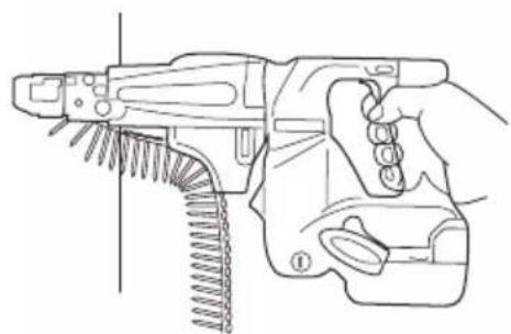
1. How to operate
Press the unit straight up against the work and pull the switch trigger to automatically feed and tighten the screws (Fig. 15).
NOTE
- Place this unit straight up against the work during screw-tightening. Using the unit while at an angle to the work might damage the screw head or cause bit wear. Also the proper tightening torque will not be transmitted to the screw and might cause the screw to seat improperly.
○ Press firmly on the unit until the screw tightening is complete. Loosening the pushing pressure on the unit might cause the screw to seat improperly. - When driving the screw, avoid hitting the unit as pushing in.
This could prevent the screw from being sent normally.
☐ Attempting to tighten one screw on top of another will cause the screw to fall or stop the screw feed so use caution.
○ Driving blanks
During continuous screw tightening, you might not notice you have run out of screws and continue to operate the unit. Driving without any screws will cause the bit to damage the lath or plaster board, so do the screw tightening while checking the number of screws remaining.
○ If the slider does not move smoothly, try cleaning the sliding surfaces with an air gun, etc.
2. Using in corners (Fig. 16)
Unit can drive screws at positions as close as 15 mm from the wall.
NOTE
Do not attempt to drive screws when closer to the wall than 15 mm.
Do not drive screws while the slider case is in contact with the wall. Damaging the screw head causes bit wear. The proper tightening torque is not transmitted to the screw if the screw head or bit is worn. This might also cause the screw not to seat properly and might cause this unit to break.
3. Removing the screws
The tightened screws can be removed by rotating them for the reverse rotation (L) (counterclockwise).
Properly install the bit against the groove on the screw head, and pull the switch trigger while depressing the bit against the groove vertically.
Or, depress the bit against the groove on the screw head vertically while pulling the switch trigger.
4. When the slider won't move smoothly
If the slider will not move smoothly, try cleaning the sliding surfaces of the slider and slider case with an air gun, etc. (Fig. 17).
NOTE
The unit tends to easily become covered with lath or plaster board dust during jobs where it faces upwards. Clean the sliding surfaces at regular periods during the work task.
5. Attaching the sheet
If the sheet has been damaged and cannot be used, please replace the sheet with attached one. Attach the sheet by inserting the holes on the sheet on the two protrusions on the stopper (Fig. 18).
6. Using the hook
The hook is used to hang up the power tool to your waist belt while working.
CAUTION
○ When using the hook, hang up the power tool firmly not to drop accidentally.
If the power tool is dropped, it may lead to an accident.
When carrying the power tool with hooked to your waist belt, do not fit any bit to the tip of power tool. If the sharp bit such as drill is fitted to the power tool when carrying it with hooked to your waist belt, you will be injured.
○ Install securely the hook. Unless the hook is securely installed, it may cause an injury while using.
(1) Removing the hook.
Remove the screws fixing the hook with Philips screw driver. (Fig. 19)
(2) Replacing the hook and tightening the screws.
Install securely the hook in the groove of power tool and tighten the screws to fix the hook firmly. (Fig. 20)
7. About Remaining Battery Indicator
When pressing the remaining battery indicator switch, the remaining battery indicator lamp lights and the battery remaining power can be checked. (Fig. 21)
When releasing your finger from the remaining battery indicator switch, the remaining battery indicator lamp goes off. The Table 4 shows the state of remaining battery indicator lamp and the battery remaining power.
Table 4
| State of lamp | Battery Remaining Power |
 | The battery remaining power is enough. |
| [2474] | The battery remaining power is a half. |
| [H63K] | The battery remaining power is nearly empty.Re-charge the battery soonest possible. |
As the remaining battery indicator shows somewhat differently depending on ambient temperature and battery characteristics, read it as a reference.
NOTE
○ Do not give a strong shock to the switch panel or break it. It may lead to a trouble.
To save the battery power consumption, the remaining battery indicator lamp lights while pressing the remaining battery indicator switch.
8. Confirm that the battery is mounted correctly
SCREW HANDLING
NOTE
Handle both the packed box of screws and the collated screw strips with care. If you drop them, screws can come out of the collated tape and cause screw feed malfunctions. Do not expose the screws to prolonged periods of direct sunlight or outside air. They can cause rust and collated tape problems, so when you will not be using the screws for awhile, put them in the screw packing box or the like.
MAINTENANCE AND INSPECTION
1. Inspecting the driver bit
Using a broken bit or one with a worn out tip is dangerous because the bit can slip. Replace it by a new one.
2. Inspecting the mounting screws
Regularly inspect all mounting screws and ensure that they are properly tightened. Should any of the screws be loose, retighten them immediately. Failure to do so could result in serious hazard.
3. Maintenance of the motor
The motor unit winding is the very “heart” of the power tool.
Exercise due care to ensure the winding does not become damaged and/or wet with oil or water.
4. Inspecting the carbon brushes (Fig. 22)
The motor employs carbon brushes which are consumable parts. Since and excessively worn carbon brush can result in motor trouble, replace the carbon brush with new ones when it becomes worn to or near the “wear limit”. In addition, always keep carbon brushes clean and ensure that they slide freely within the brush holders.
NOTE
When replacing the carbon brush with a new one, be sure to use the HiKOKI Carbon Brush Code No. 999054.
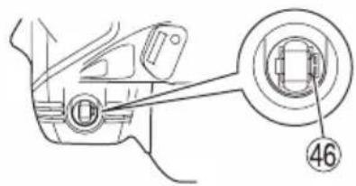
5. Replacing carbon brushes
Take out the carbon brush by first removing the brush cap and then hooking the protrusion of the carbon brush with a flat head screw driver, etc., as shown in Fig. 24.
When installing the carbon brush, choose the direction so that the nail of the carbon brush agrees with the contact portion outside the brush tube. Then push it in with a finger as illustrated in Fig. 25. Lastly, install the brush cap.
CAUTION
Be absolutely sure to insert the nail of the carbon brush into the contact portion outside the brush tube. (You can insert whichever one of the two nails provided). Caution must be exercised since any error in this operation can result in the deformed nail of the carbon brush and may cause motor trouble at an early stage.
6. Cleaning on the outside
When the driver drill is stained, wipe with a soft dry cloth or a cloth moistened with soapy water. Do not use chloric solvents, gasoline or paint thinner, for they melt plastics.
7. Storage
Store the driver drill in a place in which the temperature is less than 40^ C and out of reach of children.
NOTE
Storing lithium-ion batteries.
Make sure that the battery is fully charged when stored for a long period (3 months or more). The battery with smaller capacity may not be able to be charged when used, if stored for a long period.
Storing lithium-ion batteries.
Make sure the lithium-ion batteries have been fully charged before storing them.
Prolonged storage (3 months or more) of batteries with a low charge may result in performance deterioration, significantly reducing battery usage time or rendering the batteries incapable of holding a charge.
However, significantly reduced battery usage time may be recovered by repeatedly charging and using the batteries two to five times.
If the battery usage time is extremely short despite repeated charging and use, consider the batteries dead and purchase new batteries.
CAUTION
In the operation and maintenance of power tools, the safety regulations and standards prescribed in each country must be observed.
Important notice on the batteries for the HiKOKI cordless power tools
Please always use one of our designated genuine batteries. We cannot guarantee the safety and performance of our cordless power tool when used with batteries other than these designated by us, or when the battery is disassembled and modified (such as disassembly and replacement of cells or other internal parts).
GUARANTEE
We guarantee HiKOKI Power Tools in accordance with statutory/country specific regulation. This guarantee does not cover defects or damage due to misuse, abuse, or normal wear and tear. In case of complaint, please send the Power Tool, undismantled, with the GUARANTEE CERTIFICATE found at the end of this Handling instruction, to a HiKOKI Authorized Service Center.
NOTE
Due to HiKOKI's continuing program of research and development, the specifications herein are subject to change without prior notice.
Information concerning airborne noise and vibration
The measured values were determined according to EN62841 and declared in accordance with ISO 4871.
Measured A-weighted sound power level: 91 dB (A)
Measured A-weighted sound pressure level: 80 dB (A) Uncertainty KpA: 3 dB (A).
Wear ear protection.
Vibration total values (triax vector sum) determined according to EN62841.
No load
Screwdriving without impact:
Vibration emission value ah=0.8~m/s^2
Uncertainty K = 1.5 m/s ^2
The declared vibration total value has been measured in accordance with a standard test method and may be used for comparing one tool with another.
It may also be used in a preliminary assessment of exposure.
WARNING
☐ The vibration emission during actual use of the power tool can differ from the declared total value depending on the ways in which the tool is used.
- Identify safety measures to protect the operator that are based on an estimation of exposure in the actual conditions of use (taking account of all parts of the operating cycle such as the times when the tool is switched off and when it is running idle in addition to the trigger time).
natural_image
Two line drawings showing a hand holding a handgun, with no text or symbols present.Visser sans percussion :
VEILIGHEIDSWAARSCHUWINGEN
SCHAKELAARWERKING (AFB. 4)
LET OP
natural_image
Line drawing of a quill pen with inkwell (no text or symbols)| English Nederlands | |
| GUARANTEE CERTIFICATE1 Model No.2 Serial No.3 Date of Purchase4 Customer Name and Address5 Dealer Name and Address(Please stamp dealer name and address) | GARANTIEBEWIJS1 Modelnummer2 Serienummer3 Datum van aankoop4 Naam en adres van de gebruiker5 Naam en adres van de handelaar(Stempel a.u.b. naam en adres vande de handelaar) |
| Deutsch Español | |
| GARANTIESCHEIN1 Modell-Nr.2 Serien-Nr.3 Kaufdatum4 Name und Anschrift des Kunden5 Name und Anschrift des Händlers(Bitte mit Namen und Anschrift des Handlers abstem-peln) | CERTIFICADO DE GARANTÍA1 Número de modelo2 Número de serie3 Fecha de adquisición4 Nombre y dirección del cliente5 Nombre y dirección del distribuidor(Se ruega poner el sello del distribuidor con su nombre y dirección) |
| Français Português | |
| CERTIFICAT DE GARANTIE1 No. de modèle2 No de série3 Date d’achat4 Nom et adresse du client5 Nom et adresse du revendeur(Cachet portant le nom et l’adresse du revendeur) | CERTIFICADO DE GARANTIA1 Número do modelo2 Número do série3 Data de compra4 Nome e morada do cliente5 Nome e morada do distribuidor(Por favor, carímbe o nome e morada do distribuidor) |
| Italiano Ελληνικά | |
| CERTIFICATO DI GARANZIA1 Modello2 N° di serie3 Data di acquisto4 Nome e indirizzo dell’acquirente5 Nome e indirizzo del rivenditore(Si prega di apporre il timbro con questi dati) | ΠΙΣΤΟΠΟΙΗΤΙΚΟ ΕΓΓΥΗΣΗΣ1 Αρ. Μοντέλου2 Αύξων Αρ.3 Ημερομηνία αγοράς4 Όνομα και διεύθυνση πελάτη5 Όνομα και διεύθυνση μεταπωλητή(Παρακαλούμε να χρησιμοποιηθεί σφραγίδα) |
HiKOKI
| 1 | |
| 2 | |
| 3 | |
| 4 | |
| 5 |

natural_image
Line drawing of a quill pen with inkwell (no text or symbols)
natural_image
Line drawing of a quill pen with inkwell (no text or symbols)Siemensring 34, 47877 willich, Germany
Tel: +49 2154 49930
Fax: +49 2154 499350
URL: http://www.hikoki-powertools.de
Hikoki Power Tools Netherlands B.V.
Brabanthaven 11, 3433 PJ Nieuwegein, The Netherlands
Tel: +31 30 6084040
Fax: +31 30 6067266
URL: http://www.hikoki-powertools.nl
Hikoki Power Tools (U.K.) Ltd.
Precedent Drive, Rooksley, Milton Keynes, MK 13, 8PJ,
United Kingdom
Tel: +44 1908 660663
Fax: +44 1908 606642
URL: http://www.hikoki-powertools.uk
Hikoki Power Tools France S.A.S.
Hikoki Power Tools Belgium N.V./S.A.
Koningin Astridlaan 51, B-1780 Wemmel, Belgium
Tel: +32 2 460 1720
Fax: +32 2 460 2542
URL http://www.hikoki-powertools.be
Hikoki Power Tools Italia S.p.A
Via Piave 35, 36077, Altavilla Vicentina (VI), Italy
Tel: +39 0444 548111
Fax: +39 0444 548110
URL: http://www.hikoki-powertools.it
Hikoki Power Tools Ibérica, S.A.
C/ Puigbarral, 26-28, Pol. Ind. Can Petit, 08227 Terrassa
(Barcelona), Spain
Tel: +34 93 735 6722
Fax: +34 93 735 7442
URL: http://www.hikoki-powertools.es


- GENERAL POWER TOOL SAFETY WARNINGS
- WARNING
- 1) Work area safety
- 2) Electrical safety
- 3) Personal safety
- 4) Power tool use and care
- CORDLESS AUTOMATIC SCREWDRIVER SAFETY WARNINGS
- ADDITIONAL SAFETY WARNINGS
- CAUTION
- CAUTION ON LITHIUM-ION BATTERY
- REGARDING LITHIUM-ION BATTERY TRANSPORTATION
- SPECIFICATIONS
- STANDARD ACCESSORIES
- OPTIONAL ACCESSORIES (sold separately)
- APPLICATIONS
- BATTERY REMOVAL/INSTALLATION
- Battery removal
- Battery installation
- CHARGING
- NOTE
- Regarding electric discharge in case of new batteries, etc.
- How to make the batteries perform longer
- PRIOR TO OPERATION
- SWITCH ACTION (FIG. 4)
- Reversing switch action (Fig. 5)
- ADJUSTING THE SCREW LENGTH AND SCREW-IN DEPTH
- Set the screw length (Fig. 6)
- Adjust the screw-in depth (Fig. 7)
- INSTALLING AND REMOVING THE SCREW STRIP
- Install (Fig. 8)
- Removal (Fig. 11)
- INSTALLING AND REMOVING THE BIT
- Removing the screw strip attachment
- Attaching and removing the bit (Fig. 14)
- Installing the screw strip attachment
- HOW TO USE
- How to operate
- Using in corners (Fig. 16)
- Removing the screws
- When the slider won't move smoothly
- Attaching the sheet
- Using the hook
- About Remaining Battery Indicator
- Confirm that the battery is mounted correctly
- SCREW HANDLING
- MAINTENANCE AND INSPECTION
- Inspecting the driver bit
- Inspecting the mounting screws
- Maintenance of the motor
- Inspecting the carbon brushes (Fig. 22)
- Replacing carbon brushes
- Cleaning on the outside
- Storage
- Important notice on the batteries for the HiKOKI cordless power tools
- GUARANTEE
- Information concerning airborne noise and vibration
- No load
- VEILIGHEIDSWAARSCHUWINGEN
- SCHAKELAARWERKING (AFB. 4)
- LET OP
- Hikoki Power Tools Netherlands B.V.
- Hikoki Power Tools (U.K.) Ltd.
- Hikoki Power Tools France S.A.S.
- Hikoki Power Tools Belgium N.V./S.A.
- Hikoki Power Tools Italia S.p.A
- Hikoki Power Tools Ibérica, S.A.
Brand : HiKOKI
Model : WF18DSL
Category : Screwdriver