Jet 3500/20 Automatic - Water pump HOZELOCK - Free user manual and instructions
Find the device manual for free Jet 3500/20 Automatic HOZELOCK in PDF.
User questions about Jet 3500/20 Automatic HOZELOCK
0 question about this device. Answer the ones you know or ask your own.
Ask a new question about this device
Download the instructions for your Water pump in PDF format for free! Find your manual Jet 3500/20 Automatic - HOZELOCK and take your electronic device back in hand. On this page are published all the documents necessary for the use of your device. Jet 3500/20 Automatic by HOZELOCK.
USER MANUAL Jet 3500/20 Automatic HOZELOCK
natural_image
Technical line drawing of a mechanical pump assembly (no text or symbols)
Special warning, read carefully
Précautions particulères, lire attentivement
- Directive ROHS 2011/65/EU
1 - Safety Measures...... p.6
2 - Area of application.... p.6
3 - Technical characteristics and performance ...... p.7
4 - Description ...... p.7
5 - Preparation - First use ...... p.7
6 - Maintenance and storage...... p.8
7 - Operation faults / solutions ...... p.8
8 - Warranty ...... p.9
9 - EC declaration of conformity.... p.9
Illustrations and performance curve.... p.50

For safety reasons, this appliance can be used by children aged from 8 years and above and persons with reduced physical, sensory or mental capabilities or lack of experience and knowledge if they have been given supervision or instruction concerning use of the appliance in a safe way and understand the hazards involved. Children shall not play with the appliance. Cleaning and user maintenance shall not be made by children without supervision.
1 - SAFETY MEASURES READ CAREFULLY BEFORE USE
The user is responsible to third parties for all matters resulting in the use of the pump (electrical, hydraulic installation, etc ...). In France, comply with standard NF C15-100 of 07/00, which governs low voltage electrical installations. In other countries, comply with local regulations.
Before using the pump, it is therefore advisable to have an experienced electrician check that the necessary safety measures on the electrical network are observed.
The supply characteristics indicated on the pump rating plate must correspond to the characteristics of the electrical network.
For safety reasons, the electrical network that powers your pump must be equipped with a residual current device (RCD) having a rated residual operating current not exceeding 30 mA and grounded plugs.
This pump must be installed on a stable, flat and dry surface.
If you add an extension cord, it must be of type H07 RNF with the same section as the power cable of your pump, with a waterproof connection plug.

Never carry the pump by the power cable, but by the carry handle.

Do not make any changes to the pump. Do not modify or attempt to access the pump in any way.
If the appliance or the supply cord is damaged, it must be repaired by manufacturer, its service agent or qualified person.
Our guarantee is excluded for the normal wear of the material, deterioration or accidents resulting from a faulty and abnormal use of the equipment, or due to a modification of the pump or an intervention on the electric part.

In case of non-compliance with the instructions, the user incurs a risk that can lead to electrocution.
2 - AREA OF APPLICATION
Hazelock watering pumps are intended for private and domestic use. They make it possible to draw water without particles and to supply water under pressure to housing or garden attachments (sprinklers, spear, etc ...).
The water drawn must not exceed the temperature of 35^ C.
This pump is not designed to be used in a swimming pool, a garden pond or other similar places (aquarium, fountain, filter for the fish tanks, waterfalls, etc.).
THIS PUMP MUST NOT RUN DRY.

Attention: This pump is not suitable for removing salt water, corrosive products, flammable, explosive or food liquids.

Do not dispose of electrical appliances as unsorted municipal waste, use separate collection facilities. Contact you local government for information regarding the collection systems available.
If electrical appliances are disposed of in landfills or dumps, hazardous substances can leak into the groundwater and get into the food chain, damaging your health and well-being.
When replacing old appliances with new ones, the retailer is legally obligated to take back your old appliance for disposals at least free of charge.

The packaging of the pump is 80% recyclable.
The device and its accessories contain materials (including plastics) which can be
recycled.
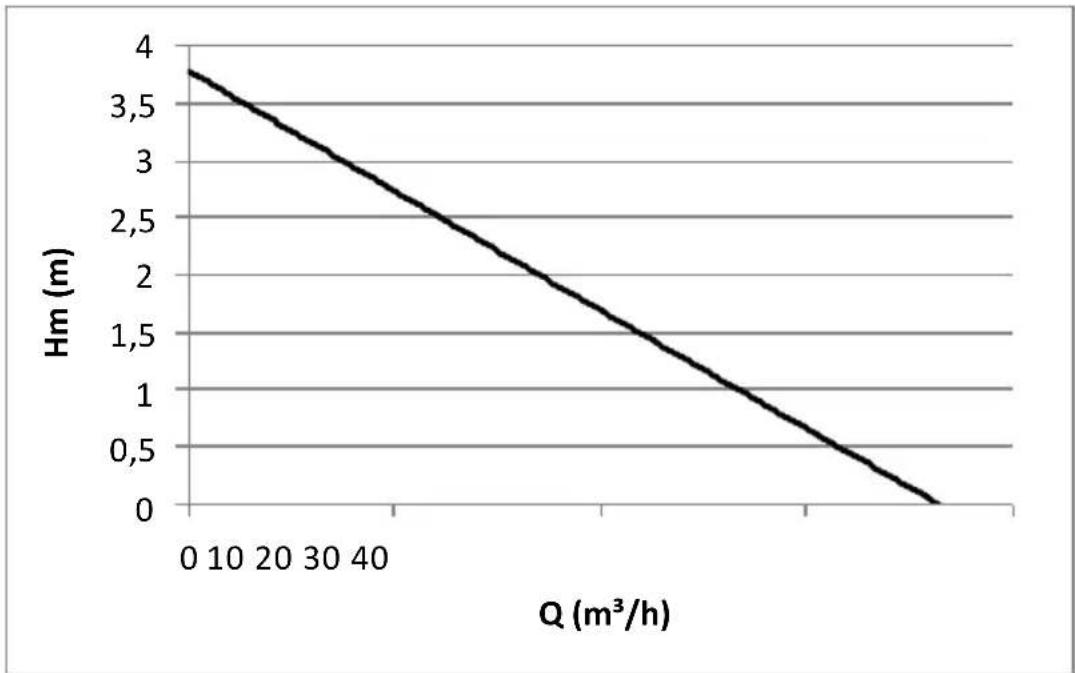
3 - TECHNICAL SPECIFICATIONS AND PERFORMANCE
See performance curve (page 52)
Values are given ±10%
Electrical data
Max. flow 3500 l/h (min.)
Max. pressure 4 bar (min.)
Min. / Max. head 2 m / 40 m (min.)
Max. suction height 7 m
Level of protection IPX4
Jet 3500/20 Automatic
220-240V\~ - 50Hz - 800 W (max.)
4 - DESCRIPTION (Fig.1-2)
A - Pump Body
B - Power cable (socket depending on country)
C - Carry handle
D - Outlet port
E - Coupler 1"/1¼" male/male
F - Nut for fitting
G - Multistage curved connector
H - High flow coupling
I - Filling cap
J- Filter
K - Water fill
L - Entry port
M - Drain cap
N - User manual
O - Switch
P - Spanner
Q - Non-return valve
R - Filter
S - Coupler 1"/1" male/male
T - Suction hose (7m)
U - Intermediate tank (20l total)
V - Pressure regulation assembly
5 - PREPARATION - FIRST USE
- Connection of the hoses:
Screw the male/male fitting (s) onto the inlet (L), then the suction hose (R+S+T, Fig.3).
Screw the discharge fitting (G) (taking care to place the flat gasket properly) using the nut provided (F).
The stepped discharge connection (G) allows (fig.4):
- The fitting of hoses with a diameter 25 mm and 32 mm,
- Or the screwing of a 1" female tap nose and the quick connection of suitable hose fittings
- Or the use of a supplied high-speed connection (H)
Cut off the end of the unused fitting (Fig.4).
- Installation: (Fig.6-7)

Before installation and each time the pump is used, always disconnect it from the power
supply.
To avoid accidents, never put your fingers in the mouth of the pump.
Use the handle provided to transport or lift the pump. When using for the first time with a water collector, make sure that the water collector is emptied and cleaned of all accumulated sediment, leaves and debris.
- Verify that the inlet of the suction hose is at least 150 mm below the surface of the water. If necessary, retain the end of the hose with a brick. It is advisable to prevent the filter from touching the bottom of the tank (at least 30 cm of water above the bottom) to avoid sucking up any residues. It is vital that all seals are present and that all connections are airtight.
The suction hose must not show excessive deformation (elbow, crushing, etc.) that could affect its performance.
The installation must comply with the restrictions related to the technical data of the pump.
- Unscrew the filler cap (I) using the supplied spanner (P). Fill the suction chamber via the filling hole (K) with clean water (fig.5).
Hozelock watering pumps are self-priming; therefore, they can be primed without having to fill the suction hose.
- Connect the watering hose to the outlet, ensuring that the other end of the watering hose is open and that water can drain freely when the pump is turned on.
- Starting up:
- Connect the pump to a suitable power supply, and switch on the pump using the switch (O).
- At each power up, while the suction hose is empty, the pump will start priming. This operation may take several minutes. During the priming, the pump contains a mixture of air and water, which greatly reduces the flow and makes some noise.
- When the pump is primed and ready to be used, the noise level drops, and the flow and pressure are maximized.
If one of the seals or fittings is missing, or is too tight or loose, the pump will not prime.
GB
If the pump is not primed after 5 minutes - stop it. Check the condition of the seals and fittings, and repeat the previous steps.
- Use:
The pump starts and stops automatically by opening or closing the hose end fitting (valve, pistol, etc.) using the pressure regulation system (V).
The pump is not intended for continuous use or for dry running. Do not leave it unattended, and/or use
dry run protection (Tecnotronic, optional accessory). The pump also has thermal motor protection which will stop its operation in case of overheating. If these safeguards are faulty, the pump may overheat
and may burn the user.
6 - MAINTENANCE AND STORAGE
Before working on the pump, unplug it.
Do not let the pump freeze.
Before storing the pump under cover, remove the hoses and empty the remaining water by unscrewing the drain nut (M).
7 - OPERATING ANOMALIES / SOLUTIONS
| Incidents Causes Solution | ||
| a- The pump will not start. | 1- No power supply. | 1- Check that the plug is well inserted into the socket. Check the circuit breakers and electrical connections outside the pump. Check the condition of the cables. |
| b- The pump is running but will not flow, or flow is reduced | 1- The body of the pump is filled with air2- The discharge hose is blocked.3- Air is trapped in the supply hose, or it is clogged | 1- Check that the connections on the supply hose are tight.- Put the suction hose as straight as possible.-Repeat the priming procedure.2- Remove the discharge hose and unblock it.3 - Check that the strainer is well immersed.-Check the suction height- Clean the strainer and/or the valve |
| c- The pump stops during operation | 1- The power supply is not consistent with the motor data of the pump.2- A solid body has blocked the hydraulic system.3- The pump worked with too hot water.4- The pump has run dry | Disconnect the pump, remove any blockage, wait for the pump to cool down and connect it again. |
For any other anomaly, contact our after-sales service. For safety reasons, only the Hozelock-Exel after-sales service is entitled to disassemble the pump.
8 - GUARANTEE
Extended Contractual Warranty
We guarantee our products for a period stated on the product from their date of purchase (Mandatory Contractual Warranty cover extended to 2 years + Extension of our Contractual Warranty).
In the event of failure to present proof of the product date of purchase, the Warranty is effective from the product date of manufacture (stated on the product).
Contractual warranty exclusions
The contractual warranty does not apply in the following cases:
-The normal wear parts: seals, mechanical seals,
-The products that are used in violation of the technical recommendations,
- Products used improperly,
- Products that are not regularly maintained
- Damage to products (impacts, drops, crushing, etc.) caused due to negligence, improper maintenance, improper or abnormal use of the product,
- Replacement of a component following a loss.
Warranty activation
Please keep your proof of purchase (invoice or legible till receipt), as this will be required in the event of a claim under the Contractual Warranty.
A product under warranty that has been repaired or replaced, remains guaranteed for the remaining duration and under the original terms of the Contractual Warranty granted at the time of purchase. All returned products become the property of HOZELOCK-EXEL when replaced by a new product.
The Contractual Warranty, the terms of which are described above, does not replace the Legal Warranty.
9 - EC DECLARATION
I, the undersigned, Philippe MAREY – Quality Manager - hereby certify that the product
Type: Watering pump
Brand: HOZELOCK
Model: Jet 3500/20 Automatic
Ref: 7610 1240
Was developed, designed and manufactured in accordance with all relevant provisions of the following directives:
- LVD Directive 2014/35/EU
- EMC Directive 2014/30/EU
- ROHS directive 2011/65/EU
Signed in Villefranche, 21/12/2017

text_image
MaresD
INHALT
- Installation: (Abb. 6-7)

4 - BESCHRIJVING (fig.1-2)
A - Pomplichaam
INNEHÄLLSFÖRTECKNING
- Installation: (Fig. 6-7)

fingrene i pumpens munning.
6 - VEDLIKEHOLD OG OPPBEVARING
3 - TEKNISET OMINAISUUDET JA TOIMINNOT
text_image
Technical diagram of an electric motor with labeled components and exploded view, including parts A through N.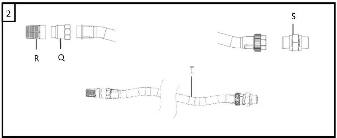
text_image
2 R Q S T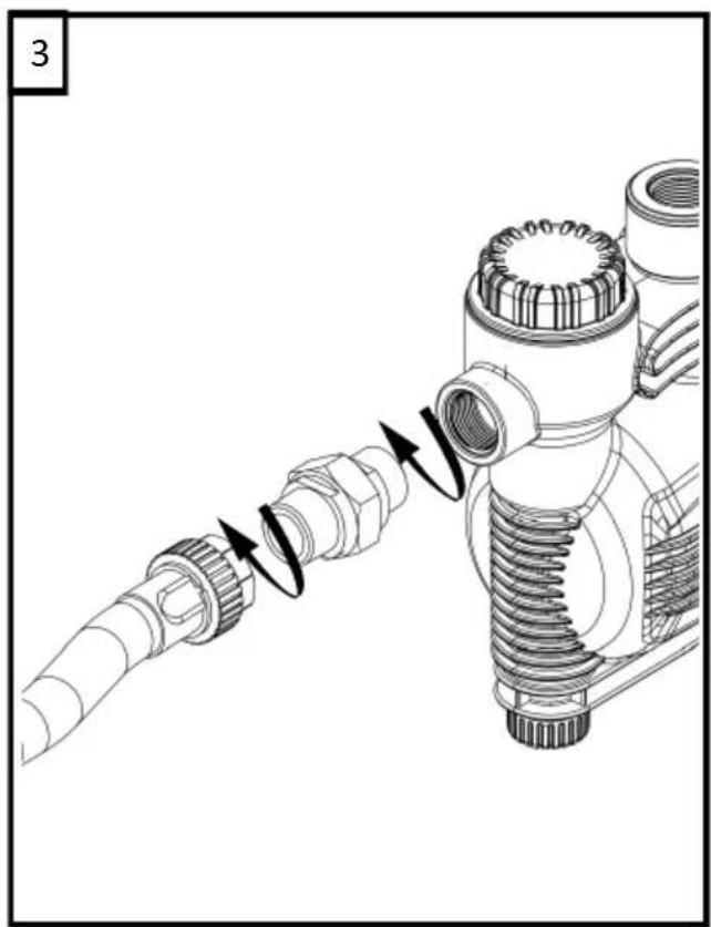
natural_image
Technical illustration of a mechanical assembly with threaded connectors and tubing (no text or symbols)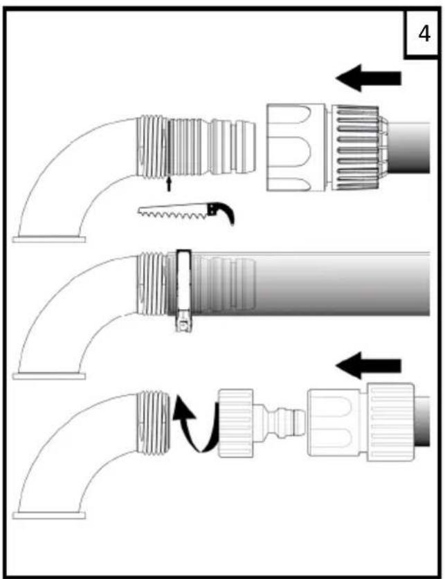
text_image
Technical diagram showing three-step installation of a pipe fitting with directional arrows indicating movement.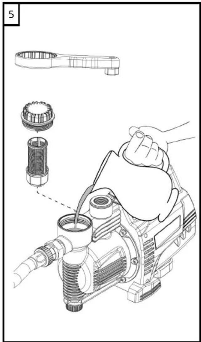
text_image
5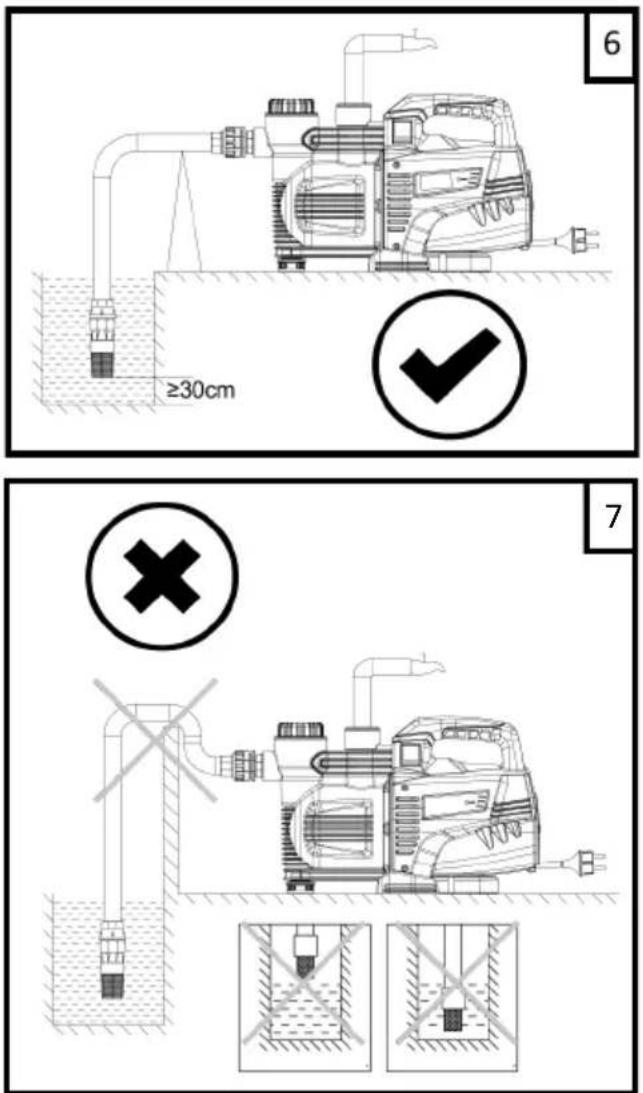
text_image
≥30cm 6 7Courbe de performances / Performance curve / Leistungskurven / Curva de rendimiento / Prestatie-curve / Curva de desempenho / Curva delle prestazioni / Prestandakurva / Ytelse kurve / Ydeevnes-kurve / Suorituskäyrä / Krzywa charakterystyki