AS5160TO - Vacuum Cleaner Viper - Free user manual and instructions
Find the device manual for free AS5160TO Viper in PDF.
User questions about AS5160TO Viper
0 question about this device. Answer the ones you know or ask your own.
Ask a new question about this device
Download the instructions for your Vacuum Cleaner in PDF format for free! Find your manual AS5160TO - Viper and take your electronic device back in hand. On this page are published all the documents necessary for the use of your device. AS5160TO by Viper.
USER MANUAL AS5160TO Viper
natural_image
Line drawing of a cleaning or cleaning service vehicle with wheels and control panels (no text or symbols)Model: 50000401 / 50000406
TABLE OF CONTENTS
ENGLISH USER MANUAL.... 1-25
FRANÇAIS MANUEL UTILISATEUR.... 26-50
ESPAÑOL INSTRUCCIONES DE USO.... 51-75
PARTS LIST 76-97
TABLE OF CONTENTS
INTRODUCTION....2
GUIDE PURPOSE AND CONTENTS....2
HOW TO KEEP THIS GUIDE....2
DECLARATION OF CONFORMITY 2
ACCESSORIES AND MAINTENANCE....2
CHANGE AND IMPROVEMENT....2
SCOPE OF APPLICATION....2
MACHINE IDENTIFICATION DATA....2
TRANSPORT AND UNPACKING....3
SAFETY 3
VISIBLE SYMBOLS ON THE MACHINE 3
SYMBOLS THAT APPEAR ON THEINSTRUCTION FOR USEMANUAL 3
GENERAL SAFETY INSTRUCTION 4
MACHINE DESCRIPTION 6
MACHINE STRUCTURE 6
CONTROL PANEL 7
DISPLAY WINDOW OF CHARGER INDICATION LIGHT 7
TECHNICAL PARAMETERS 8
WIRING DIAGRAM 9
OPERATING GUIDE ......11
BATTERY CHECK/SETTING ON A NEW MACHINE 11
BATTERY INSTALLATION AND BATTERY TYPESETTING (WET OR GEL/ AGM) 12
BRUSH/PAD-HOLDER INSTALLATION AND UNINSTALLATION 13
SOLUTION OR WASHING WATER TANK FILLING 14
MACHINE START AND STOP....14
MACHINE OPERATION (SCRUBBERING AND DRYING) 15
TANK EMPTYING 16
AFTER USING THE MACHINE....17
MACHINE LONG INACTIVITY 17
FIRST PERIOD OF USE 17
MAINTENANCE....18
SCHEDULED MAINTENANCE TABLE 18
BATTERY CHARGING....19
BRUSH/PAD CLEANING 20
SOLUTION FILTER CLEANING 20
SQUEEGEE CLEANING 21
SQUEEGEE BLADE CHECK AND REPLACEMENT 22
TANK AND VACUUM GRID WITH FLOAT CLEANING, AND COVER GASKET CHECK 23
MACHINE WORKING HOUR CHECK 24
FUSE CHECK/REPLACEMENT 24
ACCESSORIES/OPTIONS....25
TROUBLESHOOTING 25
SCRAPPING 25
INTRODUCTION

CAUTION!
Some general and detailed machine information is not included in this guide.
Please refer to Instruction for Use Manual on supplied CD-ROM reading by Adobe ^® Reader ^® .

NOTE
The numbers in brackets refer to the components shown in Machine Description chapter.
GUIDE PURPOSE AND CONTENTS
The purpose of this Quick Start Guide is to provide the operator with all basic information to use the machine properly. For information about technical characteristics, operation, machine inactivity, spare parts and safety conditions etc., please refer to Instruction for Use manual on supplied CD-ROM.
Before performing any procedure on the machine, the operators and qualified technicians must read the Instruction for Use manual. Contact our company in case of doubts concerning the interpretation of the instructions or for any further information.
HOW TO KEEP THIS GUIDE
The Quick Start Guide must be kept near the machine, inside an adequate case, away from liquids and other substances that can cause any damage to it.
DECLARATION OF CONFORMITY
Declaration of Conformity is supplied with the machine and certifies machine conformity with the law in force.

NOTE
The copies of the original declaration of conformity are provided together with the machine documentation.
ACCESSORIES AND MAINTENANCE
All the necessary operation, maintenance and repair procedures must be made by qualified personnel, our company appointed repair center. ONLY original or approved spare parts and accessories can be used.
Contact our company customer service for any service or purchase of accessories or spare parts if necessary.
CHANGE AND IMPROVEMENT
We committed to continuous improvement of its products, the company reserves the right to the machine changes and improvements without informing in additional.
SCOPE OF APPLICATION
The scrubber applies to commercial and industrial use. It is suitable for cleaning smooth and solid floor, operating by a qualified personnel in safety circumstance. It is not suitable for outdoor use or carpet or rough floor cleaning.
MACHINE IDENTIFICATION DATA
The machine serial number and model name are marked on the serial label.
This information is useful. Use the following table to write down the machine identification data when requiring spare parts for the machine.
MACHINE MODEL
MACHINE SERIAL NUMBER.
TRANSPORT AND UNPACKING
When the carrier delivers the machine, make sure the packaging and machine are both whole and undamaged. If any damaged, make the carrier know the damage and before accepting the goods, reserve the right in compensation of the damage.
Follow the instructions on packing strictly when unpacking the machine.
Check the package to ensure following items are included:
- Technical documentations including Quick Start Guide manual, Instruction for Use Disk and on-board charger manual if on-board charger is equipped.
- Charger cable if on-board charger is equipped.
- Two fuses, the low power circuit fuse (5A) and the Brush release fuse (20A).
SAFETY
The following symbols indicate potentially dangerous situations. Always read this information carefully and take all necessary precautions to safeguard people and property.
VISIBLE SYMBOLS ON THE MACHINE

WARNING!
Read all the instructions carefully before performing any operation on the machine.

WARNING!
Do not wash the machine with direct or pressurized water jets.

WARNING!
Do not use the machine on slopes with a gradient exceeding that is defined in the specification.
SYMBOLS THAT APPEAR ON THEINSTRUCTION FOR USEMANUAL

DANGER!
It indicates a dangerous situation with risk of death for the operator.

WARNING!
It indicates a potential risk of injury for people.

CAUTION!
It indicates a caution or a remark related to important or useful functions.
Pay attention to the paragraphs marked by this symbol.

NOTE
It indicates a remark related to important or useful functions.

CONSULTATION
It indicates the necessity to refer to the Instruction for Use manual before performing any procedure.
GENERAL SAFETY INSTRUCTION
Specific warnings and cautions to inform about potential damages to people and machine are shown below.

DANGER!
- This machine must be operated by trained and authorized personnel according to guidance of the manual.
- Before performing any cleaning, maintenance, repair or replacement procedure, read all the instructions carefully, ensure to turn the machine OFF and disconnect the battery connector.
- Do not operate the machine near toxic, dangerous, flammable and/or explosive powders, liquids or vapour. This machine is not suitable for collecting dangerous powders.
- Do not wear jewels when working near electrical components.
- Do not work under the lifted machine without supporting it with safety stands.
- When using lead (WET) batteries, they may emit inflammable gas under normal use, must keep sparks, flames, smoking materials and radiating, illuminating and burning items away from the batteries.
- When charging lead (WET) batteries, they may emit hydrogen gas which may cause explosive. Must ensure the charging environment is well ventilated and away from naked flames.

WARNING!
- Check the machine carefully before each use. Ensure that all the components have been well assembled before use. Or it may causes damages to people and properties.
- Before using the battery charger, ensure that the values of frequency and voltage indicated on the machine serial number label match those of mains.
- Never move the machine by pulling the battery charger cable. Do not let the cable through a closed door, or winding on sharp edges or corners. Do not run the machine on the battery charger cable. Keep the battery charger cable away from heated surfaces.
Do not charge the batteries if the battery charger cable or the plug are damaged.
• To reduce the risk of fire, electric shock, or injury, make sure machine is off before leaving.
• Use or store the machine indoors in dry conditions, it is not allowed for outdoor use.
- The machine both storage and working temperature must be between 0 °C and +40 °C, the humidity of air must be between 30% - 95%.
- Do not use the machine on slopes with a gradient exceeding as specification show.
- When using and handling floor cleaning detergents, follow the instructions on the labels of the detergent bottles and wear suitable gloves and protections.
- Use brushes and pads supplied with the machine or defined in the manual. Using other brushes or pads could reduce safety.
- In case of machine malfunctions, ensure that these are not due to lack of maintenance. If necessary, request assistance from the authorized personnel or from an authorized Service Center.
- Take all necessary precautions to prevent hair, jewels and loose clothes from being caught by the machine moving parts.
- Do not use the machine in particularly dusty areas. Do not wash the machine with direct or pressured water jets, or with corrosive substances.
- Do not bump into shelves or scaffoldings, especially where there is a risk of falling objects.
- Do not lean liquid containers on the machine, use the relevant can holder.
• To avoid damaging the floor, do not allow the brush/pad to operate while the machine is stationary.
• In case of fire, use a dry powder fire extinguisher. Do not use liquid fire extinguishers. - Do not remove or modify the machine stickers.
- Do not tamper with the machine safety guards and follow the ordinary maintenance instructions scrupulously.
- Pay attention during machine transportation when temperature is below freezing point. The water in the recovery tank and in the hoses could freeze and cause seriously damage to the machine.
- If spare parts need be replaced, order ORIGINAL spare parts from an Authorized Dealers or Retailers.
- Return the machine to the Service Center if it doesn't work as usual or it is in condition such as damaged, placed outdoors, dropped into water.
- To ensure machine proper and safe operation, the scheduled maintenance shown in the relevant chapter of this Manual, must be performed by the authorized personnel or an authorized Service Center.
- The machine must be properly disposed of, because the presence of toxic-harmful materials (batteries, etc.), which are subject to standards that require disposal in special centers (see Scrapping chapter).
• This machine as a cleaning tool only, not for any other purpose use.
- Always keep the openings free from dust, hairs and any other foreign material which could reduce the air flow. Do not use the machine if the openings are clogged.
- Use the machine only where a proper lighting is provided.
- This machine is not intended for use by persons with reduced physical, sensory or mental capabilities, or lack of experience and knowledge, unless they have been given supervision or instruction concerning use of the machine by a person responsible for their safety.
- Close attention is necessary when used near children.
• Children should be supervised to ensure that they do not play with the machine.
- While using this machine, take care not to cause damage to people or objects.
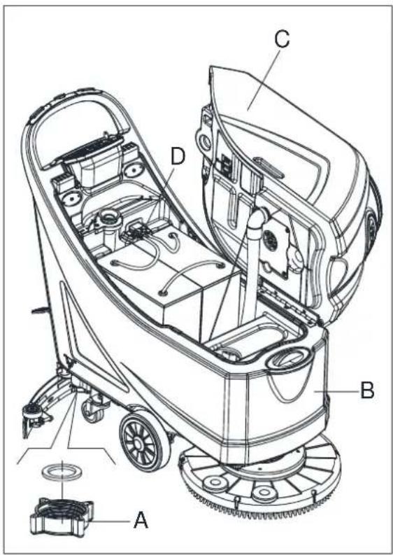
MACHINE DESCRIPTION
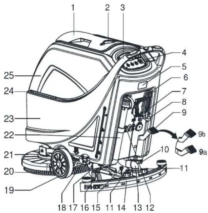
MACHINE STRUCTURE (as shown in Figure 1)
-
Recovery tank lid
-
Can holder
-
Handlebar
-
Control panel
-
Serial number plate/technical data
-
Squeegee lifting/lowering lever
-
Power supply cable holder
-
Power cable
-
Deck lifting/lowering pedal
a) Pedal position when deck is lifted
b) Pedal position when deck is lowered
-
Outlet cover
-
Squeegee knobs
- Reset label
- Squeegee vacuum hose
- Squeegee
- Squeegee balance adjusting knob
- PA Connector
- Rear steering wheels
-
Solution filter
-
Front wheels on fixed axle (A). Driving wheels (B)
- Brush/pad-holder
- Brush/pad-holder deck
- Recovery water drain hose
- Solution tank
- Hinge
- Recovery tank
- Filter support
- Filler hose holder
- Filter cover
- N/A
- Tank cover gasket
- Float ball filter
- Solenoid valve
(*): Optional
(A): Only for machine without traction
(B): Only for machine with traction
text_image
Technical diagram of a cleaning machine with numbered parts and labeled connectors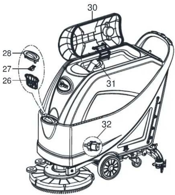
text_image
30 28 27 26 31 32Figure 1
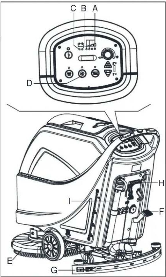
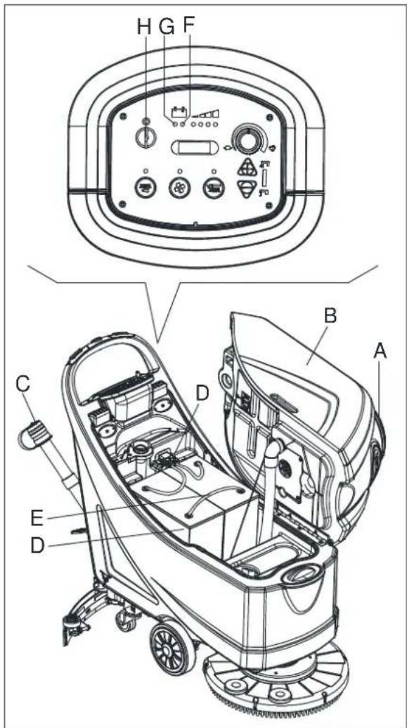
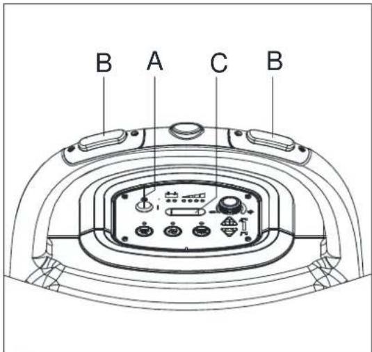
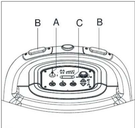
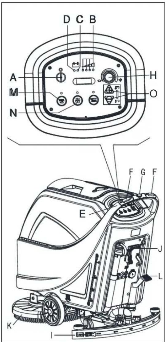
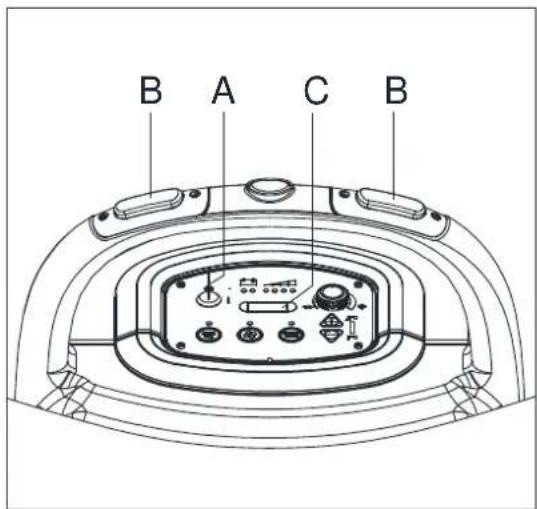
CONTROL PANEL (as shown in Figure 2)
- Machine backward switch (B)
- Safe switch
- Ignition key (0 - I)
- Discharged battery warning light (red)
- Semi-discharged battery warning light (yellow)
- Charged battery warning light (green)
- Hour meter
- Speed adjuster (B)
- Flow increase switch
- Solution flow indicator
- Flow decrease switch
- Brush/pad-holder release switch
- Vacuum system switch
- Brush/pad-holder and vacuum system switch
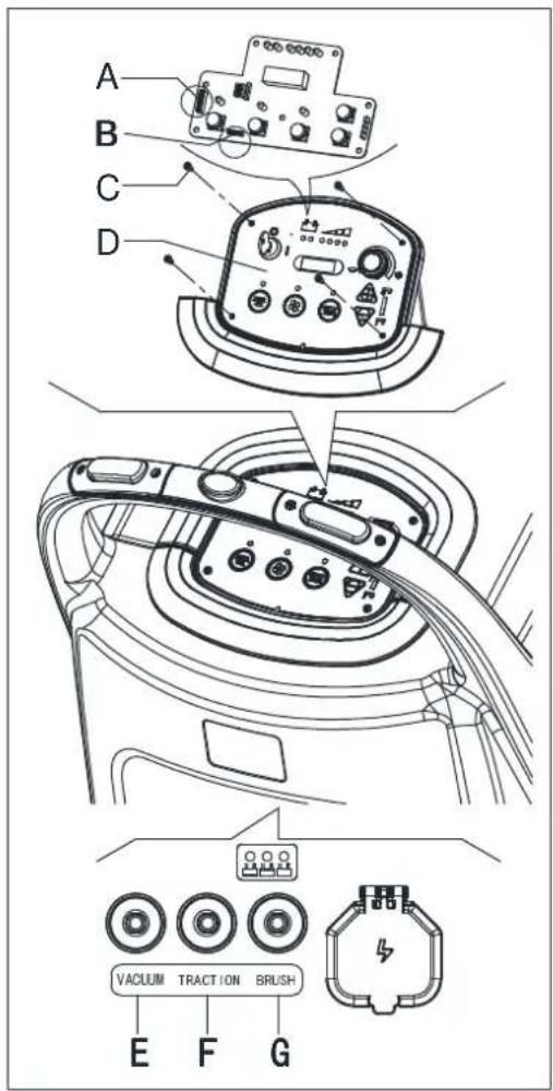
- Charging red LED
-
Charging yellow LED
-
Charging green LED
- Security cover of charging jack
- Overload protector of brush
- Overload protector of traction (B)
- Overload protector of vacuum
- Battery connector (red).
- Tank safety cable
(*): Optional
(A): Only for machine without traction
(B): Only for machine with traction
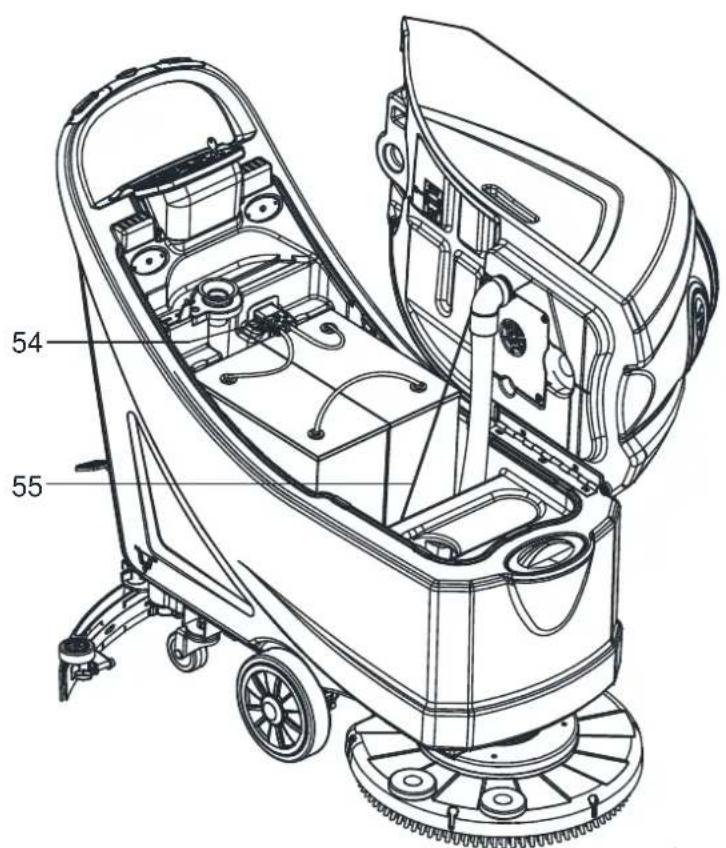
text_image
54 55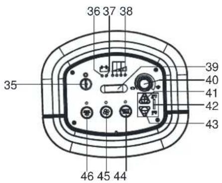
text_image
36 37 38 35 46 45 44 39 40 41 42 43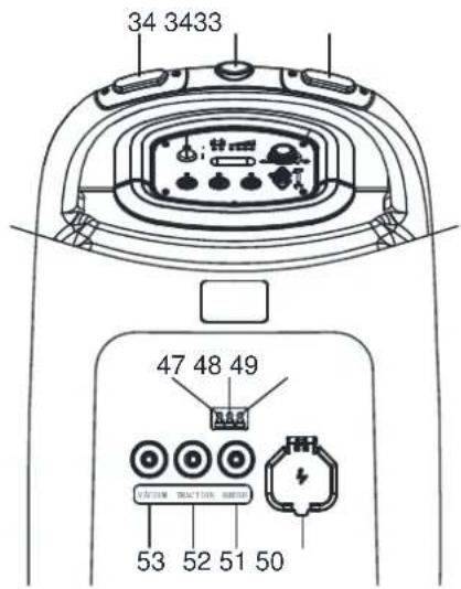
text_image
34 3433 47 48 49 53 52 51 50Figure 2
DISPLAY WINDOW OF CHARGER INDICATON LIGHT (as shown in Figure 2)
- At the beginning of charging, the red LED (47) of charger normally on. It is the first stage of charging.
- After charging some time, the red LED (47) turns off, the yellow LED (48) turns on, this is the second stage of charging.
- After charging finish, the yellow LED (48) off, the green LED (49) turns on to indicate that the battery is fully charged.

NOTE
When charging, if the yellow LED (48) of charger is on, it may be caused by: Battery and charger does not match, battery is not connected well, or output is short-circuited.
The red LED of charger flashing may be caused by charger internal short circuit.
TECHNICAL PARAMETERS
| PARAMETER TYPE USA Metric | ||||
| MODEL AS5160 AS5160T AS5160 AS5160T | ||||
| Packing dimensions (L x W x H) 54 x 24 x 48 Inches 1370 x 600 x 1220 mm | ||||
| Machine height 40 Inches 1000 mm | ||||
| Machine length 52 Inches 1310 mm | ||||
| Machine width (without squeegee) 22 Inches 550 mm | ||||
| Machine weight with empty tanks (with-out batteries) | 188 Pounds | 205 Pounds 85 Kg | 93 Kg | |
| Gross vehicle weight (GVW) | 474 Pounds | 492 Pounds | 214.8 Kg | 222.8 Kg |
| Shipping weight | 254 Pounds | 272 Pounds | 115 Kg | 123 Kg |
| Solution tank capacity | 16 Gallons | 61 Liter | ||
| Recovery tank capacity | 16 Gallons | 61 Liter | ||
| Vacuum motor power | 0.5 H.P. | 350 Watt | ||
| Vacuum capacity | 47 In. H2O | 1200 mm H2O | ||
| Climbing capacity (Max) 2% Grade | 2% | |||
| Front wheel diameter | 8 Inches | 200 mm | ||
| Rear wheel diameter | 3 Inches | 76 mm | ||
| Sound level | 69±3 dB(a) | 69±3 dB(a) | ||
| Solution/water Flow | 0 - .63 Gal./Min. | 0 - 240 CL/M | ||
| Working width | 20 Inches | 510 mm | ||
| Squeegee width | 31 Inches | 790 mm | ||
| Brush/pad diameter | 20 Inches | 510 mm | ||
| Brush motor power | 0.6 H.P. | 450 Watt | ||
| Brush speed | 150 RPM | 150 RPM | ||
| Brush/pad pressure(Max) | 60 Pounds | 50 Pounds | 27 Kg | 23 Kg |
| Drive motor power | N/A | 0.2 H.P. | N/A | 150 Watt |
| Working speed | N/A | 0-2.8 Mph | N/A | 0-4.5 Km/h |
| Voltage | 24 Volts DC | 24V DC | ||
| Battery | 105/130 Wet 105/140 AGM (Ah) | 105/130 Wet 105/140 AGM (Ah) | ||
| Battery charger | 24 Volts/ 10 Amps | 24V/ 10A | ||
| Battery compartment size (L x W x H) | 13.8 x 13.8 x 11.8 Inches | 350X350X300 mm | ||
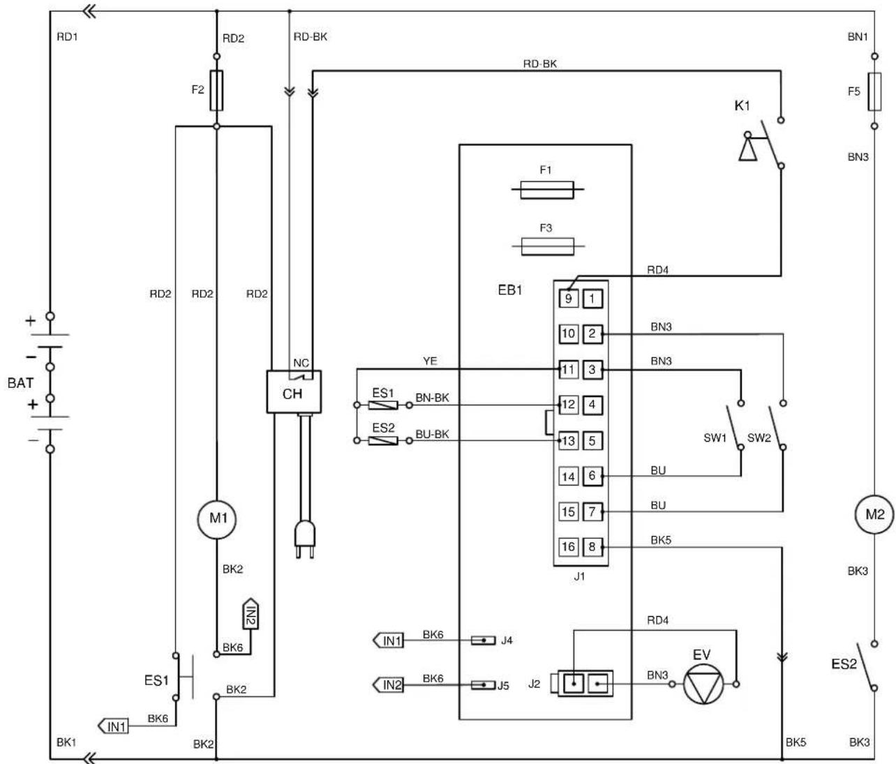
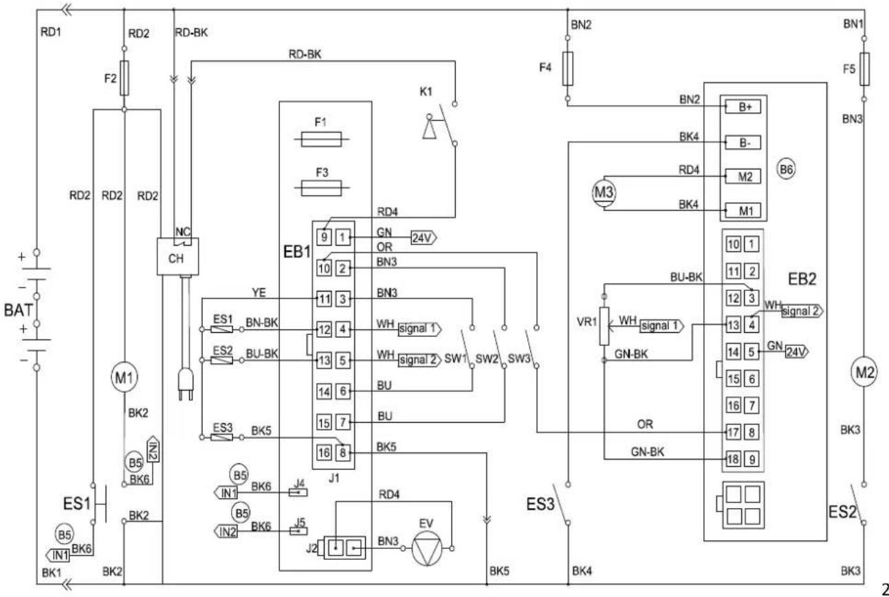
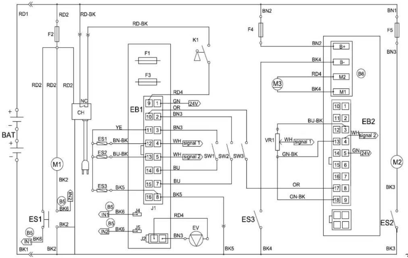
WIRING DIAGRAM (MACHINE WITHOUT TRACTION)
text_image
RD1 RD2 RD-BK RD-BK F2 F1 F3 BAT + - - - RD2 RD2 RD2 NC CH M1 BK2 ES1 BK6 BK2 IN1 BK1 BK2 RD4 EB1 9 1 10 2 11 3 12 4 13 5 14 6 15 7 16 8 J1 YE ES1 BN-BK ES2 BU-BK BN3 BN3 SW1 SW2 BU BU BK5 RD4 IN1 BK6 J4 IN2 BK6 J5 J2 BN3 EV BK5 BK3 M2 BK3 ES2 BK3| COMPONENTS WIRE ROD | |
| BAT 24V BATTERIES RD1 RED/6AWG | |
| CH BATTERY CHARGER RD2 RED/10AWG | |
| EB1 CONTROL PANEL BOARD RD4 RED/20AWG | |
| ES1 ELECTROMAGNETIC SWITCH 24V(BRUSH MOTOR) BK1 BL | |
| ES2 RELAY 24V(VACUUM MOTOR) BK2 BLACK/10AWG | |
| F1 LOW POWER CIRCUIT FUSE BK3 BLACK/12AWG | |
| F2 CIRCUIT BREAKER(BRUSH MOTOR) | |
| F3 BRUSH RELEASE FUSE | |
| F5 CIRCUIT BREAKER(VACUUM MOTOR) | |
| K1 KEY SWITCH | |
| M1 BRUSH MOTOR | |
| M2 VACUUM MOTOR | |
| EV SOLENOID VALVE | |
| SW1 SAFETY SWITCH(BRUSH) | |
| SW2 SAFETY SWITCH(BRUSH) |
| ACK/6AWG | ||
| BK5 BLACK/20AWG | ||
| BK6 BLACK/16AWG | ||
| RD-BK RED-BLACK/20AWG | ||
| BN1 BROWN/12AWG | ||
| BN3 BROWN/20AWG | ||
| BN-BK BROWN-BLACK/20AWG | ||
| BU BLUE/20AWG | ||
| BU-BK BLUE-BLACK/20AWG | ||
| YE YELLOW/20AWG | ||
| WH WHITE/20AWG | ||
WIRING DIAGRAM (MACHINE WITH TRACTION)
flowchart
graph TD
    subgraph Power Source
        RD1 --> F2
        RD2 --> RD2
        RD2 --> RD2
        RD2 --> RC
        RC --> NC
        NC --> CH
        CH --> ES1
        ES1 --> BK1
        ES1 --> BK6
        BK1 --> BK2
        BK2 --> BK6
        BK6 --> BK1
    end

    subgraph Control Circuit
        EB1 --> 9
        EB1 --> 10
        EB1 --> 11
        EB1 --> 12
        EB1 --> 13
        EB1 --> 14
        EB1 --> 15
        EB1 --> 16
        EB1 --> 17
        EB1 --> 18
        EB1 --> 19
        EB1 --> 20
        EB1 --> 21
        EB1 --> 22
        EB1 --> 23
        EB1 --> 24
        EB1 --> 25
        EB1 --> 26
        EB1 --> 27
        EB1 --> 28
        EB1 --> 29
        EB1 --> 30
        EB1 --> 31
        EB1 --> 32
        EB1 --> 33
        EB1 --> 34
        EB1 --> 35
        EB1 --> 36
        EB1 --> 37
        EB1 --> 38
        EB1 --> 39
        EB1 --> 40
        EB1 --> 41
        EB1 --> 42
        EB1 --> 43
        EB1 --> 44
        EB1 --> 45
        EB1 --> 46
        EB1 --> 47
        EB1 --> 48
        EB1 --> 49
        EB1 --> 50
    end

    subgraph Control Circuit
        ES1 --> ES2
        ES2 --> BU-BK
        BU-BK --> ES3
        ES3 --> BK5
        BK5 --> ES3

    subgraph Power Source
        ES1 --> YE
        ES1 --> YE

    subgraph Control Circuit
        EB1 --> BN3
        EB1 --> BN3

    subgraph Power Source
        EB1 --> WH_BNK_BNK_BNK_BNK_BNK_BNK_BNK_BNK_BNK_BNK_BNK_BNK_BNK_BNK_BNK_BNK_BNK_BNK_BNK_BNK_BNK_BNK_BNK_BNK_BNK_BNK_BNK_BNK_BNK_BNK_BNK_BNK_BNK_BNK_BNK_BNK_BNK_BNK_BNK_BNK_BNK_BNK_BNK_BNK_BNK_BNK_BNK_BNK_BNK_BNK_BN3
    end

    subgraph Control Circuit
        EB1 --> BN3

    subgraph Power Source
        EB1 --> WH_BNK_BNK_BNK_BNK_BNK_BNK_BNK_BNK_BNK_BNK_BNK_BNK_BNK_BNK_BNK_BNK_BNK_BNK_BNK_BNK_BNK_BNK_BNK_BNK_BNK_BNK_BNK_BNK_BNK_BN3

    subgraph Power Source
        EB1 --> WH_BNK_BNK_BNK_BNK_BNK_BNK_BNK_BNK_BNK_BNK_BNK_BNK_BNK_BN3

    subgraph Control Circuit
        EB1 --> BN3

    subgraph Power Source
        EB1 --> WH_BNK_BNK_BNK_BNK_BNK_BNK_BNK_BNK_BNK_BNK_BN3

    subgraph Power Source
        EB1 --> WH_BNK_BNK_BNK_BNK_BNK_BNK_BNK_BN3

    subgraph Control Circuit
        EB1 --> WH_BNK_BNK_BNK_BNK_BNK_BNK_BN3

    subgraph Power Source
        EB1 --> WH_BNK_BNK_BNK_BNK_BNK_BN3

    subgraph Control Circuit
        EB1 --> WH_BNK_BNK_BNK_BNK_BN3

    subgraph Power Source
        EB1 --> WH_BNK_BNK_BNK_BN3

    subgraph Control Circuit
        EB1 --> WH_BNK_BNK_BNK_BN3

    subgraph Power Source
        EB1 --> WH_BNK_BNK_BN3

    subgraph Control Circuit
        EB1 --> WH_BNK_BN3

    end

    RD1 --> RD2
    RD2 --> RD2
    RD2 --> RD-BK

    RD-BK --> RD-BK

    style Power Source fill:#f9f,stroke:#333,stroke-width:2px;
    style Control Circuit fill:#ccf,stroke:#333,stroke-width:2px
COMPONENTS WIRE ROD
| BAT | 24V BATTERIES RD1 RED/6AWG |
| CH BATTERY CHARGER RD2 RED/10AWG | |
| EB1 CONTROL PANEL BOARD RD4 RED/20AWG | |
| EB2 ELECTRONIC BOARD(TRACTION SYSTEM) BK1 BLACK/6AWG | |
| ES1 ELECTROMAGNETIC SWITCH 24V(BRUSH MOTOR) BK2 BLACK | |
| ES2 RELAY 24V(VACUUM MOTOR) BK3 BLACK/12AWG | |
| ES3 RELAY 24V(TRACTION SYSTEM) BK4 BLACK/14AWG | |
| F1 LOW POWER CIRCUIT FUSE BK5 BLACK/20AWG | |
| F2 CIRCUIT BREAKER(BRUSH MOTOR) | |
| F3 BRUSH RELEASE FUSE | |
| F4 CIRCUIT BREAKER(TRACTION SYSTEM) | |
| F5 CIRCUIT BREAKER(VACUUM MOTOR) | |
| K1 | KEY SWITCH |
| M1 BRUSH MOTOR | |
| M2 VACUUM MOTOR | |
| M3 DRIVE MOTOR | |
| EV | SOLENOID VALVE |
| SW1 | SAFETY SWITCH(BRUSH/TRACTION) |
| SW2 | SAFETY SWITCH(BRUSH/TRACTION) |
| SW3 | REVERSING SWITCH |
| VR1 | SPEED POTENTIOMETER |
| AWG | |
| BK6 BLACK/16AWG | |
| RD-BK RED-BLACK/20AWG | |
| GN GREEN/20AWG | |
| GN-BK GREEN-BLACK/20AWG | |
| BN1 BROWN/12AWG | |
| BN2 BROWN/14AWG | |
| BN3 BROWN/20AWG | |
| BN-BK BR OWN-BLACK/20AWG | |
| BU | BLUE/20AWG |
| BU-BK | BLUE-BLACK/20AWG |
| OR | ORANGE/20AWG |
| YE | YELLOW/20AWG |
| WH | WHITE/20AWG |
OPERATING GUIDE

WARNING!
On some points of the machine there are some adhesive plates indicating:
- DANGER!
- WARNING!
- CAUTION!
- CONSULTATION
While reading this Manual, the operator must pay particular attention to the symbols shown on the plates. Do not cover these plates for any reason and immediately replace them if damaged.
BATTERY CHECK/SETTING ON A NEW MACHINE

WARNING!
The electric components of the machine can be seriously damaged if the batteries are either improperly installed or connected. The batteries must be installed by qualified personnel only. Set the function electronic board and the built-in battery charger according to the type of batteries used (WET or GEL/AGM batteries). Check the batteries for damage before installation. Disconnect the battery connector and the battery charger plug. Handle the batteries with great care. Install the battery terminal protection caps supplied with the machine.

NOTE
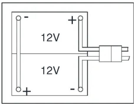
The machine requires two 12 V batteries, connected according to the diagram (Figure3).
text_image
12V 12VFigure 3
The machine can be supplied in one of the following modes:
A) Batteries (WET or GEL/ AGM) already installed and charged
- Check that the batteries are connected to the machine with the connector (54).
- Insert the ignition key (35) and turn it to "I". If the green warning light (38) turns on, the batteries are fully charged. If the yellow (37) or red warning light (36) turns on, the batteries must be charged (see the procedure in Maintenance chapter).
- Buy appropriate batteries (see the Technical Data paragraph).
- For battery choice and installation, apply to qualified battery Retailers.
- Set the machine and the battery charger according to the type of batteries (WET or GEL/ AGM), as shown in the next paragraph.
B) Without batteries
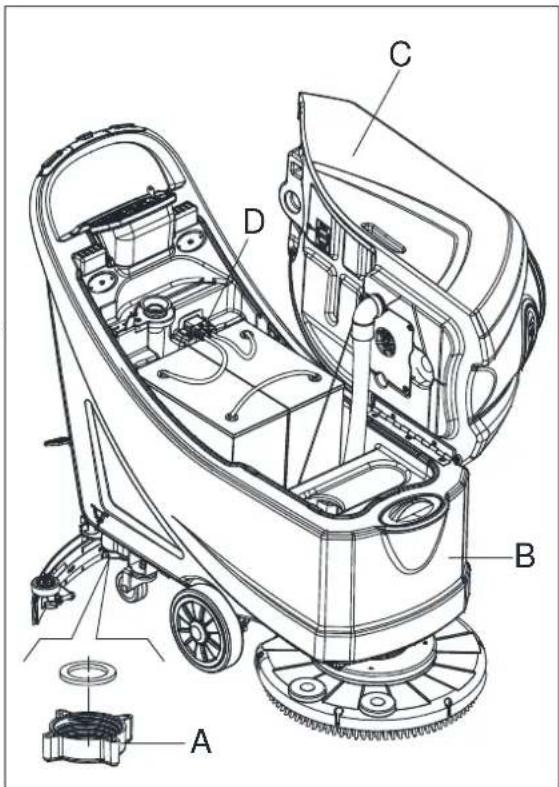
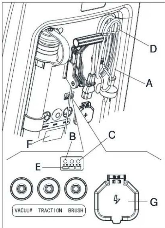
BATTERY INSTALLATION AND BATTERY TYPESETTING (WET OR GEL/ AGM)
According to the type of batteries (WET or GEL/AGM), set the machine and electronic board of the battery charger as follows:
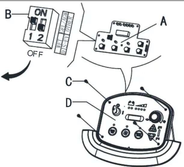
| 1 | WET BATTERIES(NOTE: Turn the DIP switch 1 and 2 both to “OFF”. ) | |
| 2 | DISCOVER EV AGM BATTERIES(NOTE: Turn the DIP switch 1 to “ON”; 2 to “OFF”. ) | |
| 3 | GENERAL GEL/AGM BATTERIES(NOTE: Turn the DIP switch 1 and 2 both to “ON”. ) |
text_image
B ON 1 2 OFF A C DFigure 4

NOTE
When install new batteries please refer to figure 4 to adjust the DIP switches. Otherwise the batteries may be damaged.
Machine setting
- Turn the ignition key (35) to “T” and in the very first seconds of machine operation pay attention to the following:
• If the first green warning light (38) is flashing, the machine is set to GEL/AGM.
• If the yellow warning light (37) is flashing, the machine is set to Discover EV AGM.
• If the red warning light (36) is flashing, the machine is set to WET.
-
If the setting need to be changed, perform the following procedure.
-
The factory setting is for discover EV AGM batteries. If the setting correspond to the battery installation, go to step6 directly. Otherwise, follow next steps4\~5.
- Remove the screws on control panel (C, Figure 4), then turn over the PCB (A Figure 4) to find the DIP switch (B, Figure 4) for setting battery type (WET or Discover EV AGM or GEL/AGM), (Refer to 1 or 2 or 3).
- If the setting complete to the battery option. Install the screws on control panel.
Battery installation
- Open the recovery tank cover (1) and check that the recovery tank (25) is empty; otherwise empty it with the drain hose.(22)
- Close the recovery tank cover (1).
- Overturn the recovery tank (25) carefully.
- The machine is supplied with cables suitable to install 2X12V batteries. Carefully put the batteries into the compartment, then install them correctly.
- Route and install the battery cable as shown in (Figure3), then carefully tighten the nut on each battery terminal.
- Place the protection cap on each terminal, then connect the battery connector (54).
- Carefully lower the recovery tank (25).
Battery charging
- Charge the batteries. (See procedures in maintenance chapter).
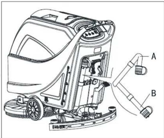
BRUSH/PAD-HOLDER INSTALLATION AND UNINSTALLATION

NOTE
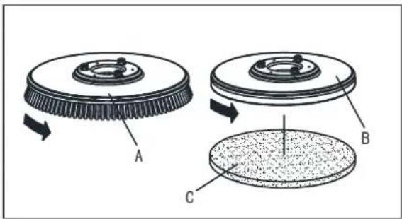
Install either the brush (A, Figure 5) or pad-holder (B and C, Figure5) according to the type of floor to be cleaned.

CAUTION!
Before installation or uninstallation of brush or pad-holder, make sure all the switches on machine are in off position and lifting up the squeegee from the floor. The operator must be equipped with suitable personnel protection devices such as gloves to reduce the risk of accidents.
Proceed as following:
-
Insert the ignition key (35) and turn it to "O".
-
Lift the deck by pressing the pedal (9).
-
If equipped, turn the speed adjuster (40) to idle by turning it counter-clockwise.
-
Place the brushes (A, Figure5) or the pad-holder (B) under the deck (21).
-
Lower the deck on the brushes/pad-holders by pressing the pedal (9).
-
Turn the ignition key (35) to "I".
-
Brush/pad-holder and vacuum system switch (46).
-
Press one of the Brush/forward gear switch (34) to engage the brush/pad-holder, then release it. If necessary, repeat the procedure until the brushes/pad-ho
-
If Step No.8 above proves to be difficult, use the manual method by turning the brush/pad-holder in the direction opposite to the normal turning direction, and it can be taken off. (as shown in Figure 5)
text_image
A B CFigure 5

WARNING!
(Only for machine with traction)Turn the speed adjuster (40) counter-clockwise to drive the machine at the minimum speed.
Slightly press the switch (34), otherwise the machine starts to move.
To engage the brush/pad-holder press the switch (34) which turns on the brush/pad-holder motor.
- To remove the brush/pad-holder lift the deck by pressing the pedal (9), then press the switch (44), the brush/pad-holder will be remove.
-
Install the squeegee and screw up the nut (H), then connect the vacuum hose (G) to the squeegee.
-
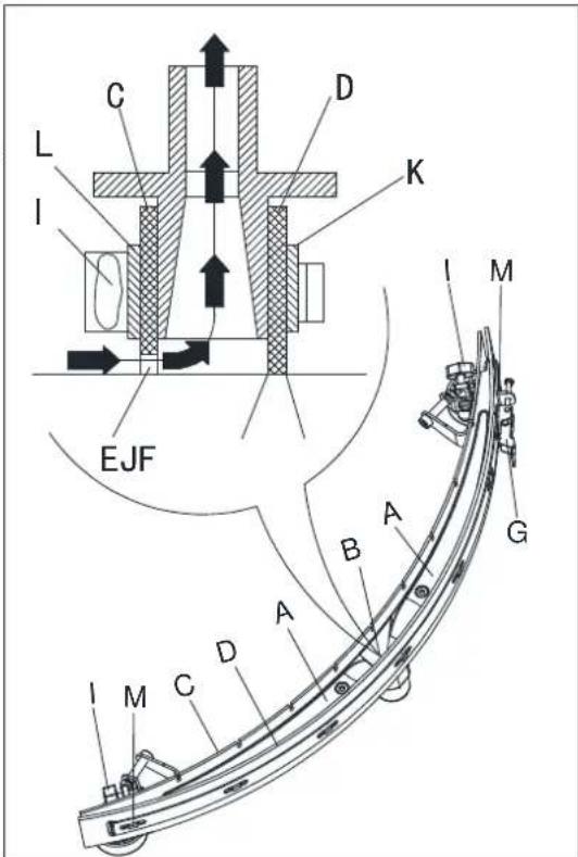
Adjust the squeegee by squeegee adjusting handle (A, Figure6).
a) If there is gap between the ground and middle section of rear squeegee blade (B), adjust the knob (A) in counterclockwise direction (F) until all section of rear squeegee blade good contact with ground, the front blade touch the ground slightly.
b) If there is gap between the ground and both end section of rear blade(C and D), adjust the knob (A) in clockwise direction (E) until all section of rear blade good contact with the ground, the front blade touch the ground slightly.
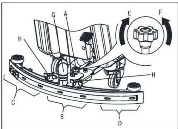
text_image
Technical diagram of a mechanical assembly with labeled components and directional arrows indicating rotation or movement.Figure 6
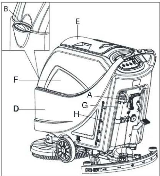
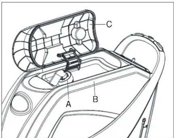
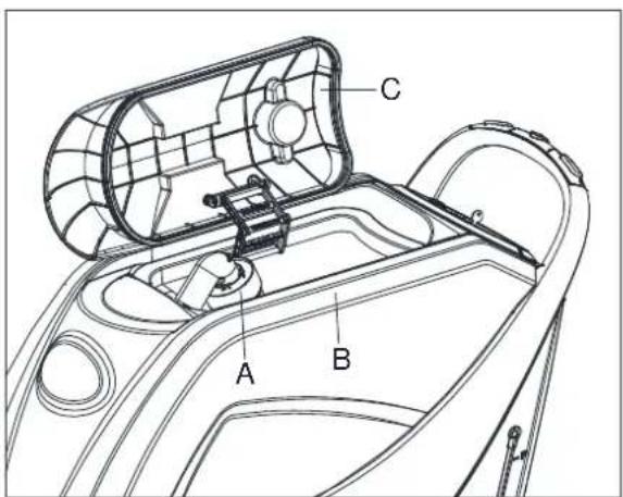
SOLUTION OR WASHING WATER TANK FILLING
- Open the water inlet cover (B, Figure 7).
-
Filling water or solution suitable for work performance through the water inlet with filter. The solution temperature must not exceed +104F (+40°C).
-
Do not overfill the tank, refer to water level indicator (H) for the water volume.

WARNING!
Use only low-foam and non-flammable detergents, intended for automatic scrubber applications.
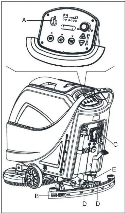
MACHINE START AND STOP
Starting the machine
- Prepare the machine as shown in the previous paragraph.
- Insert the ignition key (A, Figure8) and turn it to "I". Check that the green warning light (B) turns on (charged battery). If the yellow (C) or red warning light (D) turns on, turn the ignition key back to "0" and charge the batteries (see the procedure in Maintenance chapter).
-
Drive the machine to the working area:
-
By pushing it with the hands on the handlebar (E) (only for machine without traction).
- By pushing it with the hands on the handlebar (E) and pressing the switch (F) to move forward, or pressing the switch (F) together with the switch (G) to move backward (only for machine with traction). The forward speed can be adjusted with the adjuster (H).
- Lower the squeegee (I) with the lever (J).
- Lower the brush/pad-holder deck (K) by lifting the pedal (L).
- Press the brush/pad-holder switch (M) and the vacuum system switch (N).
- Press the washing water flow control switches (O) as necessary, depending on the type of cleaning to be performed.
- Start cleaning:
- (only for machine without traction) by pushing the machine with the hands on the handlebar (E) and pressing the switch (F).
- (only for machine with traction) by pushing the machine with the hands on the handlebar (E) and by pressing the switch (F). If necessary, the forward speed can be adjusted with the adjuster (H).

NOTE
To move the machine forward, press either the left or right switch (F) or both.
text_image
Technical diagram of a cleaning or cleaning machine with labeled parts A through H, showing internal components and component details.Figure 7
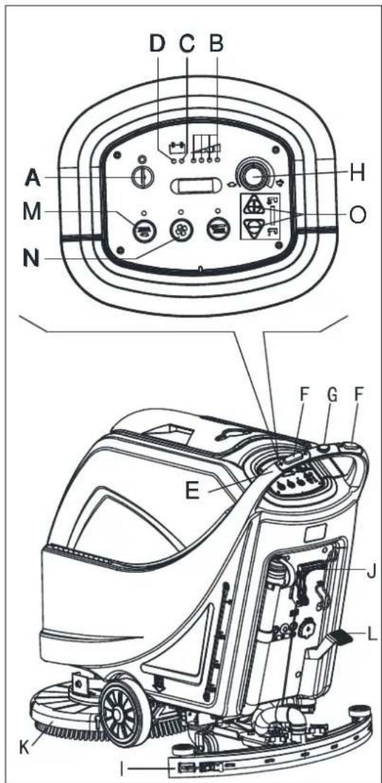
text_image
A M N D C B H O F G F E J L K IFigure 8
Stopping the machine
- Stop the machine by using the handlebar (E) (only for machine without traction). Stop the machine by releasing the switches (F) (only for machine with traction).
- Stop the brushes and the vacuum system by pressing the switch (M). The vacuum system stops after a few seconds.
- Lift the brush/pad-holder deck (K) by pressing the pedal (L).
- Lift the squeegee (I) with the lever (J).
- Turn the ignition key (A) to "0".
- Make sure that the machine cannot move independently.
MACHINE OPERATION (SCRUBBERING AND DRYING)
- Start the machine as shown in previous paragraphs.
- While keeping both hands on the handlebar press the safety switch (F, Figure8), then manoeuvre the machine and start scrubbing/drying the floor.
- If necessary, stop the machine then adjust squeegee according to section "Adjusting balance of squeegee".

NOTE
For correct scrubbing/drying of floors at the sides of the walls, Suggests to go near the walls with the right side of the machine (A and B, Figure 9) as shown in the figure.

CAUTION!
To avoid any damage to the floor surface, turn off the brushes/pad-holders when the machine stops in one place.
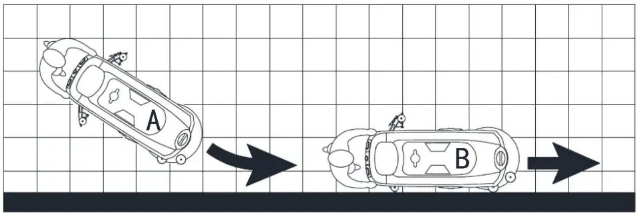
text_image
A BFigure 9
Battery discharge during operation
Until the green warning light (A, Figure10) stays on, the batteries allow the machine to work normally. When the green warning light (A) turns off, and the yellow warning light (B) turns on, it is advisable to charge the batteries, because the remaining charge will last for a few minutes (depending on battery characteristics and work to be performed). When the red warning light (C) turns on, batteries are fully discharged. After a few seconds, the brush/pad-holder is automatically tuned off, while the (only for machine with traction) drive system stay on, to finish drying the floor and drive the machine to the appointed recharging area.

CAUTION!
Do not use the machine with discharged batteries, to avoid damaging the batteries and reducing the battery life.
TANK EMPTYING
An automatic float shut-off system (A, Figure 11) blocks the vacuum system when the recovery water tank (B) is full. The vacuum system deactivation is signaled by a sudden increase in the vacuum system motor noise frequency, also the floor has not dried.

CAUTION!
If the vacuum system turns off accidentally (for example, when the float is activated because of a sudden machine movement), to resume the operation: turn off the vacuum system by pressing the switch (D, Figure 10), then open the cover (C, Figure 11) and check that the float inside the grid (A) has gone down to the water level. Then close the cover (C) and turn on the vacuum system by pressing the switch (D, Figure 10).
When the recovery water tank (B, Figure11) is full, empty it according to the following procedure.
Recovery water tank emptying
- Stop the machine.
- Lift the brush/pad-holder deck (E, Figure10) by pressing the pedal (F).
- Lift the squeegee (G) with the lever (H).
- Drive the machine to the appointed disposal area.
- Empty the recovery water tank with the hose (I). Then, rinse the tank (B, Figure11) with clean water.
text_image
C B A D I H F E GFigure 10

text_image
A B CFigure 11

CAUTION!
When draining the wastewater, the vacuum tube for waste must be folded (A, Figure 12) and lowered to a lower position (B, Figure 12), and then open the lid of the vacuum tube for waste to drain the water. Do not make the outlet of the vacuum tube for waste face upward to drain the water vertically. This is to avoid wastewater spilling onto the operator.
text_image
Technical diagram of a cleaning machine with labeled parts A and B, showing internal components and piping connections.Figure 12
- Perform steps 1 to 4.
Solution/clean water tank emptying
- Empty the solution tank with the outlet cover (A, Figure13). After working, rinse the tank with clean water.
AFTER USING THE MACHINE
After working, before leaving the machine:
- Remove the brushes/pad-holders.
- Empty the tanks (B and C, Figure13) as shown in the previous paragraph.
- Perform the daily maintenance procedures (see the Maintenance chapter).
- Store the machine in a clean and dry place, with the brushes/ pad-holders and the squeegee lifted or removed.
MACHINE LONG INACTIVITY
If the machine is not going to be used for more than 30 days, proceed as follows:
- Perform the procedures shown in After Using the machine paragraph.
- Disconnect the battery connector (54).
text_image
Technical diagram of a cleaning or cleaning machine with labeled components A, B, C, DFigure 13
FIRST PERIOD OF USE
After the first 8 hours, check the machine fastening and connecting parts for proper tightening and check the visible parts for wear and leakage.
MAINTENANCE

WARNING!
Maintenance procedures must be performed after the machine is turned off and the battery charger cable is disconnected. In addition, carefully read the safety chapters in the manual.
All scheduled or extraordinary maintenance procedures must be performed by qualified personnel or an authorized Service Center. This manual only describes the general and common maintenance procedures.
For other maintenance procedures that are not in below maintenance schedule table, please refer to the Service Manual that can be consulted at any our company Service Center.
SCHEDULED MAINTENANCE TABLE

CAUTION!
The procedure marked with (1) must be performed when the machine is used after 9 hours for the first time. The procedure marked with (2) must be done by Service Center that qualified by our company.
| Procedure Daily, after each use | Weekly | semiannually | Yearly |
| Battery charging | |||
| Squeegee cleaning | |||
| Brush/Pad-holder cleaning | |||
| Tank cleaning | |||
| Tank sealing strip inspection | |||
| Float ball filter cleaning | |||
| Squeegee blade check and replacement | |||
| Cleaning water filter cleaning | |||
| Suction filter cleaning | |||
| WET battery fluid level check | |||
| Screw and nut tightness inspection | (1) | ||
| Brush/Pad-holder carbon brush check or replacement | (2) | ||
| Suction motor carbon brush check or replacement | (2) | ||
| Drive system motor carbon brush check or replacement (only for machine with traction) | (2) |
BATTERY CHARGING

NOTE
Charge the batteries when the yellow (F, Figure 14) or red warning light (G) turns on, or when finishing cleaning.

CAUTION!
Keeping the batteries charged make their life last longer.

CAUTION!
When the batteries are discharged, charge them as soon as possible, as that condition makes their life shorter. Check for battery charge at least once a week.

WARNING!
WET battery charging produces highly explosive hydrogen gas. Charge the batteries in well-ventilated areas and away from naked flames. Do not smoke while charging the batteries. Keep the tank open while charging the batteries.

WARNING!
Pay careful attention when charging the batteries as there may be battery fluid leakages. The battery fluid is corrosive. If it comes in contact with skin or eyes, rinse thoroughly with water and consult a physician.
text_image
H G F B A C D E DFigure 14
Preliminary procedures
- Open the cover (A, Figure14) and check that the recovery water tank (B) is empty, otherwise empty it with the drain hose (C).
- Drive the machine on a level floor.
- Turn the ignition key (H) to "0".
- Carefully lift the tank (B).
-
For WET batteries only:
-
Check the level of electrolyte inside the batteries (D); if necessary, top up through the caps (E).
• Leave all the battery caps (E) open for next charging.
• If necessary, clean the upper surface of the batteries (D). -
Charge the batteries according to the following procedure.
Battery charging with battery charger installed on the machine
-
Connect the battery charger cable (A, Figure15) to the electrical mains (G) (the electrical mains voltage and frequency must be compatible with the battery charger values shown on the machine serial number plate (F). When the battery charger is connected to the electrical mains, all machine functions are automatically cut off. If the red warning light (B) on the battery charger control panel stays on, the battery charger is charging the batteries.
-
When the green warning light (C) turns on, the battery charging is completed.
-
When the battery charging is completed, disconnect the battery charger cable (A) from the electrical mains (G) and wind it round its housing (D).
-
Carefully lower the tank.

NOTE
For further information about the operation of the battery charger (E, Figure 15), see the relevant Manual.
text_image
D A F B C E VACUUM TRACTION BRUSH GFigure 15
BRUSH/PAD CLEANING

CAUTION!
It is advisable to use protective gloves when cleaning the brush/pad because there may be sharp debris.
- Remove the brush/pad from the machine, as shown in the Use chapter.
- Clean and wash the brush/pad with water and detergent.
- Check that the brushes/pads are in working condition and not excessively worn; if necessary replace them.
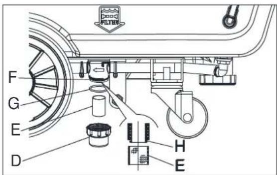
SOLUTION FILTER CLEANING
- Drive the machine on a level floor.
- Ensure that the machine is off and the ignition key (35) has been removed.
- Emptying the solution tank (Advice).
- Remove the transparent cover (D, Figure16), then remove the filter strainer (E). Clean and install them on the support (F).

NOTE
The filter strainer (E) must be correctly positioned on the housing (H) of the support (F).
text_image
F G E D H EFigure 16
SQUEEGEE CLEANING

NOTE
The squeegee must be clean and its blades must be in good conditions in order to get a good drying.

CAUTION!
It is advisable to wear protective gloves when cleaning the squeegee because there may be sharp debris.
- Drive the machine on a level floor.
- Turn the ignition key (A, Figure17) to "0".
- Lower the squeegee (B) with the lever (C).
- Loosen the knobs (D) and remove the squeegee (B).
- Disconnect the vacuum hose (E) from the squeegee.
-
Clean the steel or the aluminum squeegee (Figure18). Clean the compartments (A) and the hole (B) especially. Check the front blade (C) and the rear blade (D) for integrity, cuts and tears; if necessary replace them (see the procedure in the following paragraph).
-
Assemble the squeegee in the reverse order of disassembly.
text_image
Technical diagram of a cleaning or cleaning machine with labeled components A, B, C, D, and EFigure 17
text_image
A B C DFigure 18
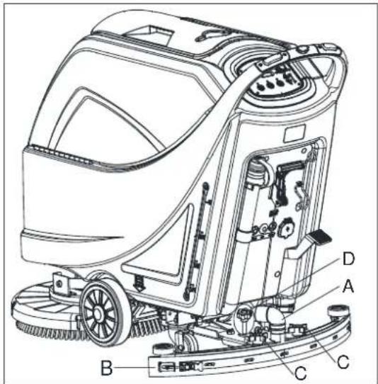
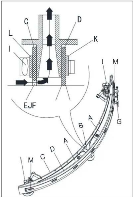
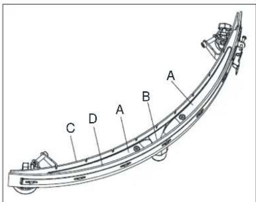
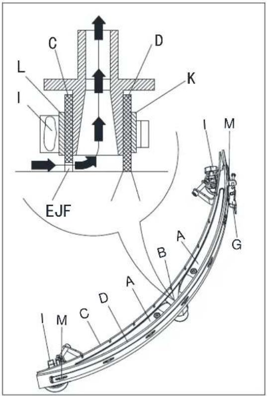
SQUEEGEE BLADE CHECK AND REPLACEMENT
-
Clean the steel or the aluminum squeegee, as shown in the previous paragraph.
-
Check that the edges (E, Figure20) of the front blade (C) and the edges (F) of the rear blade (D) lay down on the same level, along their length; if necessary adjust their height according to the following procedure:
- Remove the tie rod (G), disengage the fasteners (M) and adjust the rear blade (D), then engage the fasteners (M) and install the tie rod (G).
- Loosen the knobs (I) and adjust the front blade (C), then tighten the knobs.
- Check the front blade (C) and rear blade (D) for wear, cuts and tears; if necessary replace them according to the following procedure. Check that the front corner (J) of the rear blade (D) is not worn; if necessary, overturn the blade to replace the worn corner with an integral one. If the other corners are worn too, replace the blade according to the following procedure:
- Remove the tie rod (G), disengage the fasteners (M) and remove the retaining strip (K), then replace/overturn the rear blade (D). Assemble the blade in the reverse order of disassembly.
- Unscrew the knobs (I) and remove the retaining strip (L), then replace the front blade (C). Assemble the blade in the reverse order of disassembly. After the blade replacement (or overturning), adjust the height as shown in the previous step.
-
Connect the vacuum hose (A, Figure19) to the squeegee.
-
Install the squeegee (B) and screw down the knobs (C).
-
If necessary, adjust the squeegee balance adjusting knob (D).
text_image
Technical diagram of a cleaning or cleaning machine with labeled parts A, B, C, DFigure 19
text_image
C L I D K EJF I M B A G A M C DFigure 20
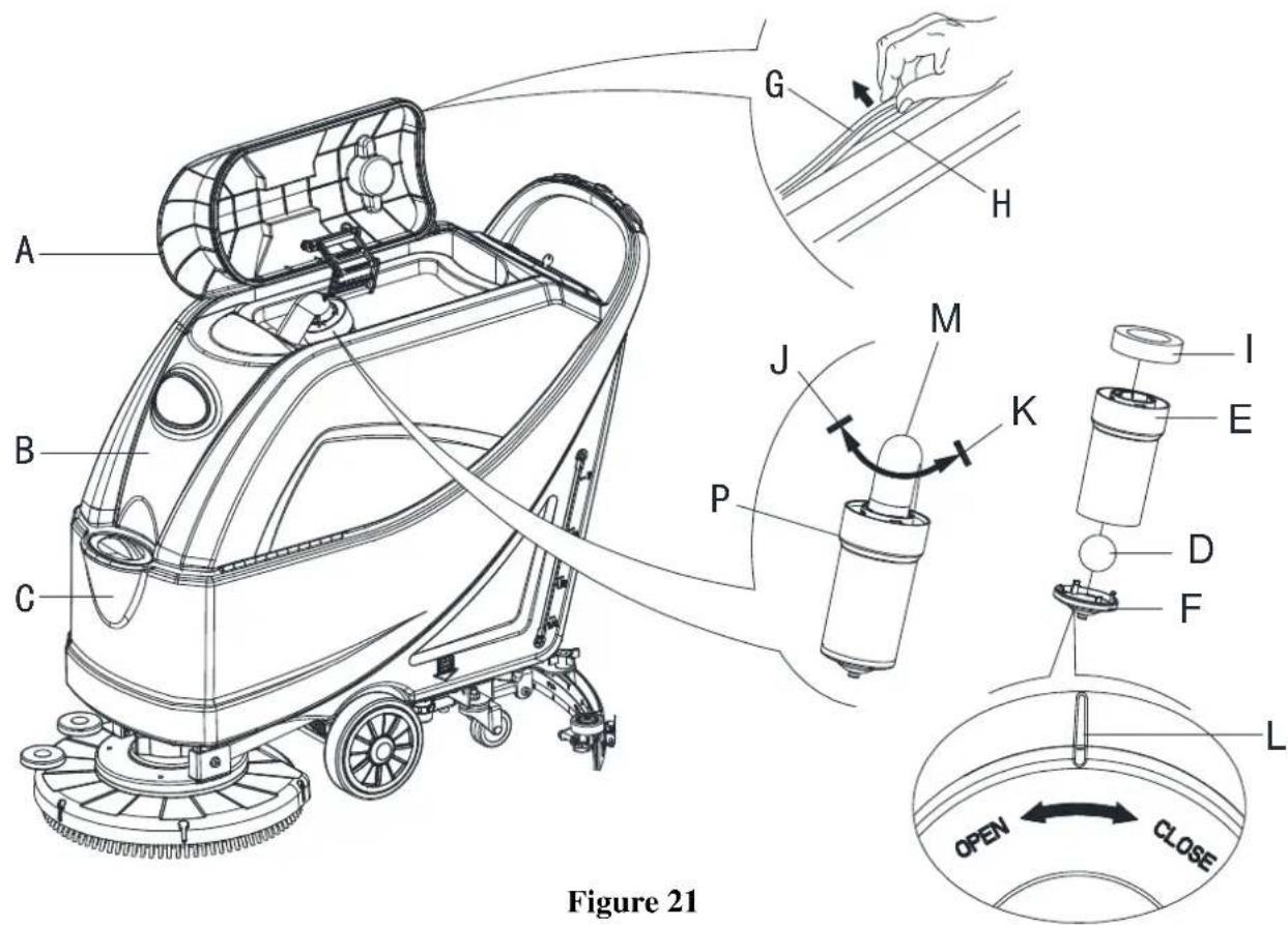
TANK AND VACUUM GRID WITH FLOAT CLEANING, AND COVER GASKET CHECK
- Drive the machine on a level floor.
- Ensure that the machine is off and the ignition key (54) has been removed.
- Turn the recovery tank lid (A, Figure21) 90 degree position where it can be took off from the tank, and then take down the float ball filter (P) from the tank.
- Clean the recovery tank lid (A), recovery tank (B), clean water tank(C) and the float ball filter support frame (E). Empty the recovery tank with the drain hose (B, Figure23).
- If necessary, follow the symbols "OPEN" and "CLOSE" as shown in (Figure21) to open the bottom cover (F) of float ball filter and then clean the float ball (D), filter support frame (E) and filter sponge (I). After cleaning, fix the float ball (D) into the filter support frame (E) and then align the mark groove (L) of the bottom cap (F) of the float ball filter with the mark groove (L) of the float filter support frame (E). Screw the bottom cap of the float ball filter tight, and fix the filter sponge (I) onto the float filter support frame (E). Finally, connect it to the sewage suction hose (M).
- Inspect the integrity of the tank sealing strip.

NOTE
Tank sealing strip (G) makes to produce the vacuum inside the tank when suction motor works. The tank must be sealed can effectively absorb the water from the ground to recovery tank.
- Check whether the contact surface of sealing strip (G) is integrity and sealing is sufficient. If necessary, take the sealing strip of the tank out of the groove (H) and replace it. Assembly the new sealing strip as shown in (Figure21), the joint should be back in the middle area.
- Close the recovery tank lid (A).
text_image
Figure 21 A B C G H J M K P I E D F L OPEN CLOSEMACHINE WORKING HOUR CHECK
- Turn the ignition key (A, Figure22) to "I".
- Press the switch (B), the hour meter (C) begins to work and it at the same time shows the total number of working hours (scrubbing/drying) performed by the machine.
- Release the switch (B).
- Turn the ignition key (A) to "0".
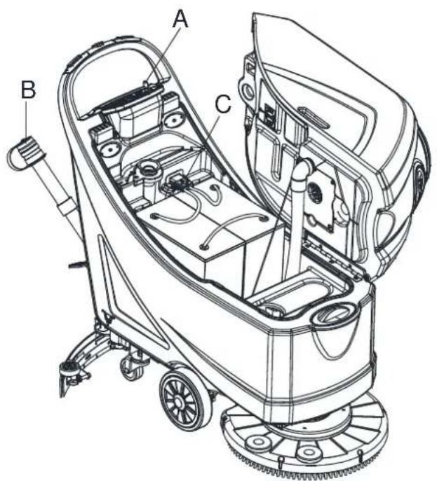
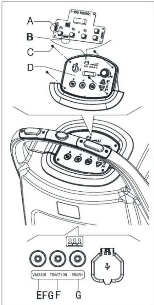
FUSE CHECK/REPLACEMENT
- Turn the ignition key (A, Figure22) to "0".
- Disconnect the power supply cable(C, Figure23) from the electrical mains.
-
Remove the screws(C .Figure24) on control panel (D), then turn over the PCB to find the fuse (A, B, Figure 24).
-
Check/replace the following fuses:
A) F1 fuse, low power circuit fuse:(5A)
B) F3 fuse, Brush release fuse: (20A) - Perform steps 1 to 3 in the reverse order.
- Check/press down or replace the following breakers:
E) F5breaker, vacuum motor circuit breaker: (30A)
F) F4 breaker, drive system circuit breaker: (12A) (*)
G) F2breaker, brush motor circuit breaker: (30A)
(*): Only for machine with traction
text_image
Technical diagram of a cleaning or cleaning machine with labeled components A, B, and CFigure 23
text_image
B A C BFigure 22
text_image
A B C D VACUUM TRACTION BRUSH E F GFigure 24
ACCESSORIES/OPTIONS
In addition to the standard components, the machine can be equipped with the following accessories/options, according to the machine specific use:
For further information concerning the above-mentioned optional accessories, contact an authorized Retailer.
ACCESSORIES/OPTIONS
See "Parts List" section
- GEL/AGM batteries
- Pads of different materials
TROUBLESHOOTING
| Trouble Probable | causes Remedy | |
| The motors do not work; no warning light turns on. | The battery connector is disconnected. Connect the battery connector. | |
| The batteries are completely discharged. Charge the batteries. | ||
| The machine does not move (Only for machine with traction) | The machine has been turned on by using the ignition key and by keeping one of the switches pressed. | Turn the ignition key to “0”, then try to start the machine again without pressing the switches. |
| The 3 battery charge indicators are flashing simultaneously. | Brush motor overload. Use less aggressive brushes | |
| Foreign materials (tangled threads, etc.) which may prevent the brush from rotating. | Clean the brush hub. | |
| The brushes do not work, the red warning light is on. | The batteries are discharged. | Charge the batteries. |
| The recovery water vacuuming is insufficient. | The recovery water tank is full. | Empty the tank. |
| The hose is disconnected from the squeegee. | Connect. | |
| The vacuum grid is clogged or the float is stuck closed. | Clean the grid or check the float. | |
| The squeegee is dirty or the squeegee blades are worn or damaged. | Clean and check the squeegee. | |
| The tank cover is not properly closed, or the gasket is damaged, or the Bend tube is clogged. | Close the cover correctly, or replace the gasket or clean the Bend tube. | |
| The recovery water tank is dirty. | Clean. | |
| The solution flow to the brushes is insufficient. | The solution/clean water filter is dirty. Clean the filter. | |
| The squeegee leaves marks on the floor. | There are debris under the squeegee blades. | Remove the debris. |
| The squeegee blades are worn, chipped or torn. | Replace the blades. | |
| The squeegee has not been adjusted with the knob. | Adjust. | |

NOTE
Machine with battery charger installed, cannot operate if the charger is not on board. In case of battery charger malfunction, contact an authorized Service Center.
For further information refer to the Service Manual, available at any Service Center.
SCRAPPING
Scrap the machine by the qualified waste treatment institution.
Before the machine is scrapped, please take away and segregate below subassembly that relevant laws and regulations request must be disposed in appropriate way.
- Battery
- Brush/Pad-holder
- lastic hose and plastic parts
- Electrical and electronic components (*)
(*) Please contact our company service center for any destroy of electrical and electronic components.
TABLE DES MATIÈRES
INTRODUCTION....27
BUT ET CONTENU DU GUIDE 27
COMMENT CONSERVER CE GUIDE....27
DÉCLARATION DE CONFORMITÉ....27
ACCESSOIRES ET ENTRETIEN....27
CHANGEMENT ET AMÉLIORATION....27
CHAMP D'APPLICATION 27
DONNÉES D'IDENTIFICATION DE LA MACHINE....27
TRANSPORT ET DÉBALLAGE....28
SÉCURITÉ 28
SYMBOLES VISIBLES SUR LA MACHINE....28
SYMBOLES QUI APPARAISSENT SUR LE MANUEL D'UTILISATION 28
CONSIGNES GÉNÉRALES DE SÉCURITÉ 29
DESCRIPTION DE LA MACHINE....31
STRUCTURE DE LA MACHINE....31
PANNEAU DE COMMANDE....32
FENÊTRE D'AFFICHAGE DU VOYANT DU CHARGEUR.... 32
PARAMÈTRES TECHNIQUES....33
SCHÉMA DE CÂBLAGE 34
GUIDE D'UTILISATION....36
VÉRIFICATION/RÉGLAGE DE LA BATTERIE SUR UNE NOUVELLE MACHINE 36
INSTALLATION DES BATTERIES ET RÉGLAGE DU TYPE DE BATTERIE (AVEC ENTRETIEN OU GEL/AGM)....37
INSTALLATION ET DÉSINSTALLATION DE LA BROSSE / DU SUPPORT DE DISQUE .... 38
AJUSTEMENT DE L'ÉQUILIBRE DE L'EMBOUCHURE 38
REMLISSAGE DU RÉSERVOIR AVEC UNE SOLUTION OU DE L'EAU 39
DÉMARRAGE/ARRÊT DE LA MACHINE....39
FONCTIONNEMENT DE LA MACHINE (LAVAGE ET SÉCHAGE) 40
VIDANGE DU RÉSERVOIR 41
APRÈS UTILISATION DE LA MACHINE....42
LONGUE INACTIVITÉ DE LA MACHINE 42
PREMIÈRE PÉRIODE D'UTILISATION....42
ENTRETIEN 43
CALENDRIER D'ENTRETIEN PROGRAMME....43
CHARGEMENT DES BATTERIES 44
NETTOYAGE DE LA BROSSE/DU DISQUE....45
NETTOYAGE DU FILTRE DE SOLUTION....45
NETTOYAGE DE L'EMBOUCHURE 46
VÉRIFICATION ET REMPLACEMENT DE LA LAMELLE DE L'EMBOUCHURE 47
NETTOYAGE DU RÉSERVOIR ET DE LA GRILLE D'ASPIRATION AVEC LE FLOTTEUR, VÉRIFICATION DU JOINT DE COUVERCLE....48
VÉRIFICATION DES HEURES DE TRAVAIL DE LA MACHINE 49
VÉRIFICATION/REEMPLACEMENT DU FUSIBLE....49
ACCESSOIRES/OPTIONS....50
DÉPANNAGE 50
RECYCLAGE 50
INTRODUCTION

MISE EN GARDE!
DÉCLARATION DE CONFORMITÉ
SCHÉMA DE CÂBLAGE (MACHINE AVEC TRACTION)
flowchart
graph TD
    subgraph Power Source
        RD1 --> F2
        RD2 --> RD2
        RD2 --> RD2
        RD2 --> RD2
        RD2 --> RD2
        RD2 --> RD2
        RD2 --> RD2
        RD2 --> RD2
        RD2 --> RD2
        RD2 --> RD2
        RD2 --> RD2
        RD2 --> RD2
        RD2 --> RD2
        RD2 --> RD2
        RD2 --> RD2
        RD2 --> RD2

    subgraph Control Circuit
        ES1 --> BK1
        ES1 --> BK6
        ES1 --> BK2
        ES1 --> BK6
        ES1 --> BK1
        ES1 --> BK6
        ES1 --> BK2
        ES1 --> BK6
        ES1 --> BK1
        ES1 --> BK6
        ES1 --> BK2
        ES1 --> BK6
        ES1 --> BK1
        ES1 --> BK6
        ES1 --> BK2
        ES1 --> BK6
        ES1 --> BK1
        ES1 --> BK6
    end

    subgraph Power Supply
        ED1["EB1"] --> YE
        ED1 --> BN-BK1["ES1"]
        ED1 --> BN-BK2["ES2"]
        ED1 --> BU-BK1["ES2"]
        ED1 --> BU-BK2["ES3"]
        ED1 --> BK5["ES3"]
        ED1 --> BK6["BN-BK"]
        ED1 --> BK6["BN-BK"]
        ED1 --> BK5["BN-BK"]
        ED1 --> BK5["BN-BK"]
        ED1 --> BK5["BN-BK"]
        ED1 --> BK5["BN-BK"]
        ED1 --> BK5["BN-BK"]
    end

    subgraph Control Circuit
        EB2["EB2"] --> BS6["BS6"]
        EB2 --> BS3["BS3"]
        EB2 --> BS4["BS4"]
        EB2 --> BS5["BS5"]
        EB2 --> BS6["BS6"]
        EB2 --> BS7["BS7"]
        EB2 --> BS8["BS8"]
        EB2 --> BS9["BS9"]
    end

    subgraph Power Supply
        BS6 --> B6["BB6"]
        BS3 --> BS4["BB4"]
        BS4 --> BS5["BB5"]
        BS5 --> BS6["BB6"]
        BS6 --> BS7["BB7"]
        BS7 --> BS8["BB8"]
        BS8 --> BS9["BB9"]
    end

    subgraph Control Circuit
        BS6 --> BM3["M3"]
        BS3 --> BM4["M2"]
        BS4 --> BM5["M1"]
    end

    style Power Supply fill:#f9f,stroke:#333,stroke-width:2px
    style Control Circuit fill:#ccf,stroke:#333,stroke-width:2px
| COMPOSANTS FIL MACHINE | |||
| BAT BATTERIES DE 24V RD1 ROUGE/6AWG | |||
| CH CHARGEUR DE BATTERIES RD2 ROUGE/10AWG | |||
| EB1 PANNEAU DE COMMANDE RD4 ROUGE/20AWG | |||
| EB2 CIRCUIT ÉLECTRONIQUE (SYSTÈME DE TRACTION) BK1 NOIRE/6AWG | |||
| ES1 COMMUTATEUR ÉLECTROMAGNÉTIQUE DE 24V (MOTEUR DE LA BROSSE) | BK2 NOIR/10AWG | ||
| ES2 RELAIS DE 24V (MOTEUR DE L'ASPIRATEUR) | BK3 NOIR/12AWG | ||
| ES3 RELAIS DE 24V (SYSTÈME DE TRACTION) | BK4 NOIR/14AWG | ||
| F1 FUSIBLE DU FAIBLE CIRCUIT ÉLECTRIQUE | BK5 NOIR/20AWG | ||
| F2 DISJONCTEUR (MOTEUR DE LA BROSSE) | BK6 NOIR/16AWG | ||
| F3 FUSIBLE À RELÂCHEMENT DE LA BROSSE | RD-BK | ROUGE-NOIR/20AWG | |
| F4 DISJONCTEUR (SYSTÈME DE TRACTION) | GN | VERT/20AWG | |
| F5 DISJONCTEUR (MOTEUR DE L'ASPIRATEUR) | GN-BK | VERT-NOIR/20AWG | |
| C1 CLÉ DE CONTACT | BN1 MARRON/12AWG | ||
| M1 MOTEUR DE LA BROSSE | BN2 NOIR/14AWG | ||
| M2 MOTEUR DE L'ASPIRATEUR | BN3 MARRON/20AWG | ||
| M3 MOTEUR D'ENTRAÎNEMENT | BN-BK MARRON-NOIR/20AWG | ||
| EV ÉLECTROVANNE | BU | BLEU/20AWG | |
| SW1 COMMUTATEUR DE SÉCURITÉ (BROSSE/TRACTION) | BU-BK | BLEU-NOIR/20AWG | |
| SW2 COMMUTATEUR DE SÉCURITÉ (BROSSE/TRACTION) | OU | ORANGE/20AWG | |
| SW3 CONTACTEUR-INVERSEUR YE JAUNE/20AWG | |||
| VR1 POTENTIOMÈTRE DE VITESSE | WH | BLANC/20AWG | |
GUIDE D'UTILISATION

AVERTISSEMENT!
text_image
Technical diagram of a mechanical assembly with labeled components and directional arrows indicating rotation or movement.Figure 6
REMLISSAGE DU RÉSERVOIR AVEC UNE SOLUTION OU DE L'EAU
text_image
Technical diagram of a cleaning or cleaning machine with labeled parts A through H, showing internal components and assembly details.Figure 72

text_image
D C B A H M O N F G F E J L K IFigure 82
Arrêt de la machine
text_image
C B A D I H F E GFigure 10
text_image
A B CFigure 112

MISE EN GARDE !
text_image
Technical diagram of a cleaning or cleaning machine with labeled parts A and BFigure 12
text_image
Technical diagram of a cleaning or cleaning machine with labeled components A, B, C, DFigure 13
ENTRETIEN

ATTENTION!
text_image
H G F B A C D E DFigure 14
text_image
F G E D H EFigure 162
NETTOYAGE DE L'EMBOUCHURE

REMARQUE
text_image
Technical diagram of a cleaning or cleaning machine with labeled parts A, B, C, DFigure 19
text_image
C L I D K EJF I M A B G A M C DFigure 20
NETTOYAGE DU RÉSERVOIR ET DE LA GRILLE D'ASPIRATION AVEC LE FLOTTEUR, VÉRIFICATION DU JOINT DE COUVERCLE
text_image
A B C G H J M P K I E D F L OPEN CLOSEFigure 21
VÉRIFICATION DES HEURES DE TRAVAIL DE LA MACHINE
VÉRIFICATION/REEMPLACEMENT DU FU- SIBLE
text_image
Technical diagram of a cleaning or cleaning machine with labeled components A, B, and CFigure 232
text_image
B A C BFigure 22

text_image
A B C D VACUUM TRACTION BRUSH EFG F GFigure 242
MANUEL UTILISATEUR FRANÇAIS
ACCESSOIRES/OPTIONS
text_image
Technical diagram of a cleaning or cleaning device with numbered parts labeled 1 through 25.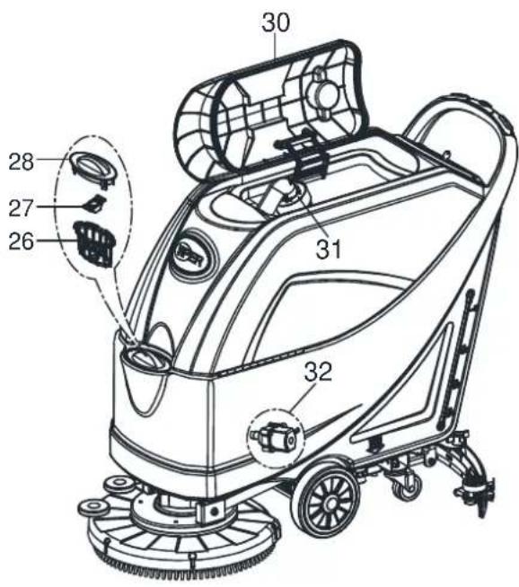
text_image
30 28 27 26 31 32Figura 1
text_image
Technical diagram of a mechanical assembly with labeled parts and directional arrows indicating rotational or mechanical motion.Figura 6
text_image
Technical diagram of a cleaning or cleaning machine with labeled parts A through H, showing internal components and assembly details.Figura 7
text_image
D C B A H M O N F G F E J L K IFigura 8
Parar la máquina
text_image
C B A D I H F E GFigura 10
text_image
A B CFigura 11
natural_image
Technical line drawing of a cleaning or cleaning machine with labeled parts A and B (no text or symbols beyond labels)Figura 12
text_image
Technical diagram of a cleaning or cleaning machine with labeled components A, B, C, and DFigura 13
MANTENIMIENTO

¡ADVERTENCIA!
text_image
H G F B A C D E DFigura 14
text_image
F G E D A C B H EFigura 16
text_image
Technical diagram of a cleaning or cleaning machine with labeled components A, B, C, D, and EFigura 17
text_image
A B C DFigura 18
text_image
Technical diagram of a cleaning or cleaning machine with labeled parts A, B, C, DFigura 19
text_image
C L I D K EJF M A B G I M C D AFigura 20
text_image
A B C G H J M K P I E D F L OPEN CLOSEFigura 21
REGISTRO DE LAS HORAS FUNCIONAMIENTO DE LA MÁQUINA
text_image
Technical diagram of a cleaning or cleaning machine with labeled parts A, B, and CFigura 23 Figura 24
text_image
B A C BFigura 22
text_image
A B C D VACUUM TRACTION BRUSH EFG F GACCESORIOS/OPCIONES
CHASSIS ASSEMBLY....86
WHEELS ASSEMBLY 88
SOLUTION ASSEMBLY....90
BRUSH ASSEMBLY....92
SQUEEGEE ASSEMBLY....94
WEAR AND TEAR PARTS....96
* = Optional
# = Modified item No. or New item No.
GENERAL VIEW
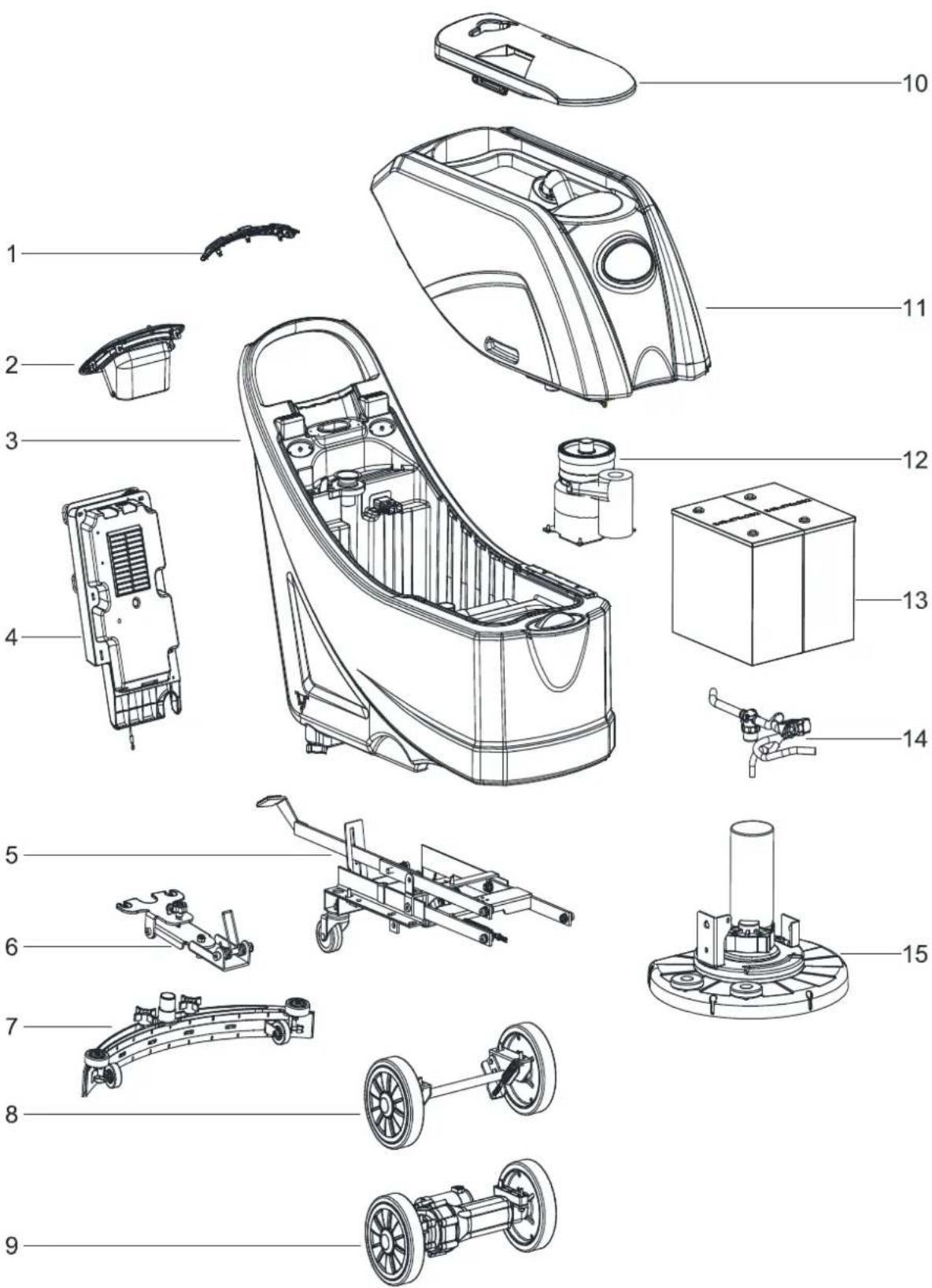
text_image
Exploded view diagram of a car interior with numbered parts for identificationGENERAL VIEW
| Item | Description | Qty |
| 1A | SAFETY SWITCH ASSEMBLY WITHOUT TRACTION | 1 |
| 1B | SAFETY SWITCH ASSEMBLY WITH TRACTION 1 | |
| 2 | CONTROL PANEL ASSEMBLY | 1 |
| 3 | SOLUTION TANK ASSEMBLY | 1 |
| 4 | CONTROL BOX ASSEMBLY | 1 |
| 5 | CHASSIS ASSEMBLY | 1 |
| 6 | SQUEEGEE HOLDER ASSEMBLY | 1 |
| 7 | 20 INCH SQUEEGEE ASSEMBLY | 1 |
| 8A | WHEEL ASSEMBLY WITHOUT TRACTION 1 | |
| 9B | WHEEL ASSEMBLY WITH TRACTION | 1 |
| 10 | RECOVERY TANK LID ASSEMBLY | 1 |
| 11 | RECOVERY TANK ASSEMBLY | 1 |
| 12 | VACUUM MOTOR ASSEMBLY | 1 |
| 13 | BATTERIES | 1 |
| 14 | SOLUTION SYSTEM ASSEMBLY | 1 |
| 15 | BRUSH DECK ASSEMBLY | 1 |
A: ONLY FOR MACHINE WITHOUT TRACTION
B : ONLY FOR MACHINE WITH TRACTION
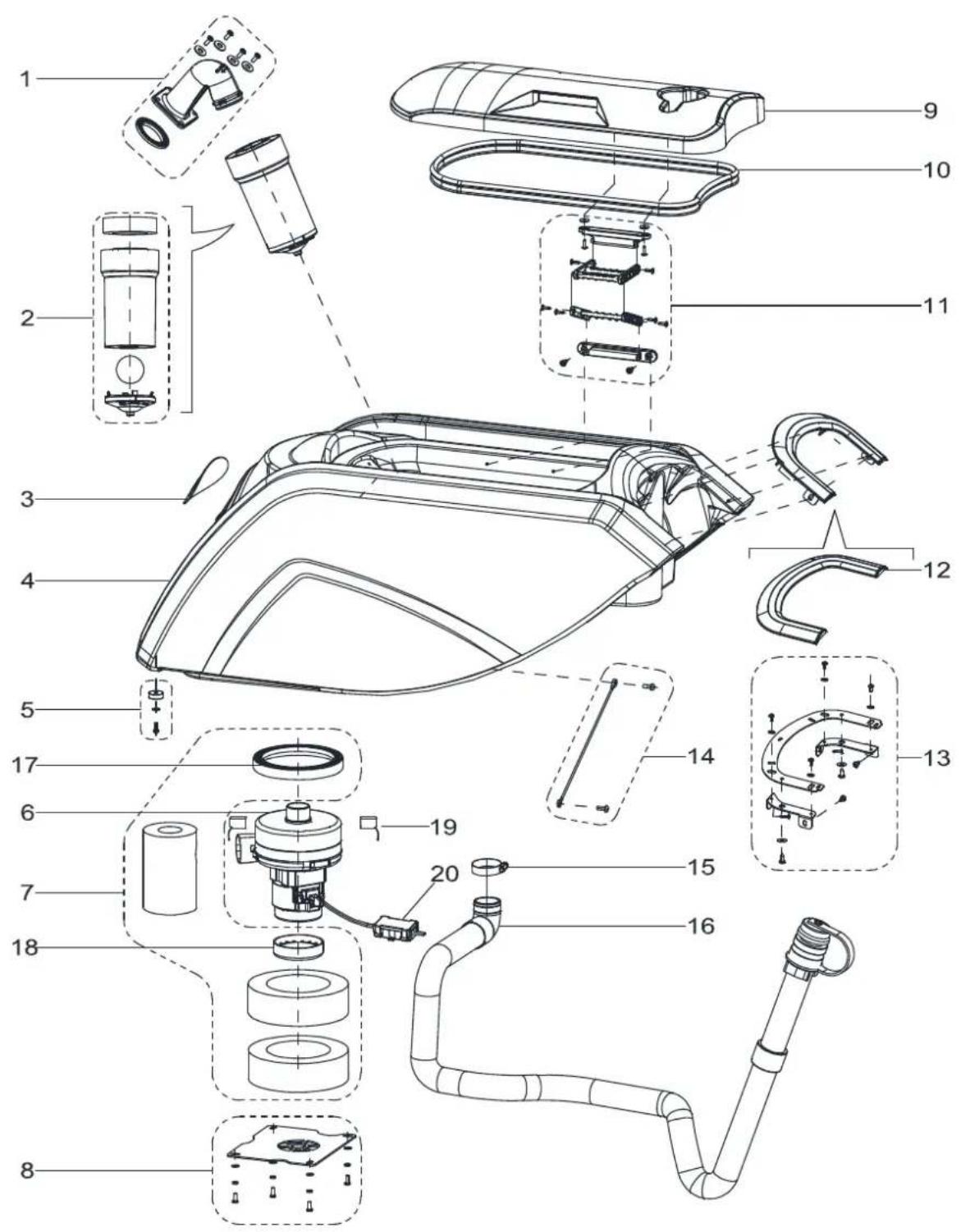
SOLUTION TANK ASSEMBLY
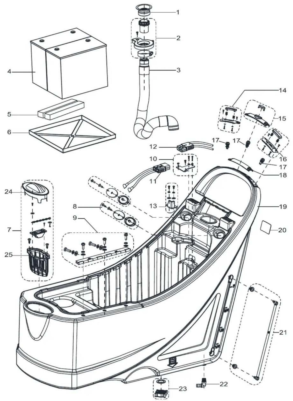
text_image
Exploded view diagram of a car interior with numbered parts for identificationSOLUTION TANK ASSEMBLY
| Item Part No. Description Qty | |||
| 1 | VS10603 DRAIN HOSE GASKET 1 | ||
| 2 | VS10101 SUCTION CONNECTER FRAME KIT 1 | ||
| 3 | VS10601 SUCTION HOSE 1 | ||
| 4 | N/A | BATTERY 12V 105~130Ah C20 WET /105~140Ah C20 AGM | 2 |
| 5 | VF90533 BATTERY SPACER PANEL 2 | ||
| 6 | VS10329 TRAY BATTERY 1 | ||
| 7 | VS10102 FILTER COVER KIT 1 | ||
| 8 | VF90265 SEAL PLATE KIT 2 | ||
| 9 | VS10103 HINGEHKIT 1 | ||
| 10 | VS10104 CHARGE PULG BRACKET KIT | 1 | |
| 11 | VS10206 BATTERY CONNECTIONS | 1 | |
| 12A | VS10217 HARNESS CONNECTER WITHOUT TRACTION | 1 | |
| 12B | VS10207 HARNESS CONNECTER WITH TRACTION | 1 | |
| 13 | VS10105 FIXED BLOCK KIT | 1 | |
| 14 | VS10106 SAFETY SWITCH RIGHT KIT | 1 | |
| 15B | VS11101 FRONT BACK SWITCH KIT | 1 | |
| 16 | VS10108 SAFETY SWITCH LEFT KIT | 1 | |
| 17 | VS10202 SWITCH | 3 | |
| 18A | VS10316 MIDDLE HANDLE COVER | 1 | |
| 19 | VS10303 SOLUTION TANK N | 1 | |
| 20 | N/A | SERIAL NUMBER LABEL | 1 |
| 21 | VS10109 WATER LEVEL PIPE KIT | 1 | |
| 22 | VF81403P | UNION ELBOW | 1 |
| 23 | VF90536 OUTLET COVER KIT T | 1 | |
| 24 | VS10312 FILTER COVER | 1 | |
| 25 | VS10313 FILTER SUPPORT | 1 | |
A: ONLY FOR MACHINE WITHOUT TRACTION
B : ONLY FOR MACHINE WITH TRACTION
RECOVERY TANK ASSEMBLY
text_image
Exploded view diagram of a washing machine with numbered parts for identificationRECOVERY TANK ASSEMBLY
| Item Part No. Description Qty | |||
| 1 | VS10110 ELBOW ADAPTOR KIT 1 | ||
| 2 | VF90534 FLOAT KIT 1 | ||
| 3 | N/A LOGO LABEL 1 | ||
| 4 | VS10302 RECOVERY TANK 1 | ||
| 5 | VS10111 RUBBER GASKET KIT 1 | ||
| 6 | VF90520 VACUUM MOTOR 1 | ||
| 7 | VS10112 GASKET VACUUM MOTOR KIT 1 | ||
| 8 | VS10113 VACUUM MOTOR COVER KIT 1 | ||
| 9 | VS10301 RECOVERY TANK LID 1 | ||
| 10 | VF90504 GASKET A 1 | ||
| 11 | VS10114 CONNECTION FRAME KIT 1 | ||
| 12 | VS10309 DECORATIVE PANEL 1 | ||
| 13 | VS10115 DECORATIVE PANEL BRACKET KIT 1 | ||
| 14 | VS10116 RECOVERY TANK CABLE KIT 1 | ||
| 15 | VA20304 CLAMP 1 | ||
| 16 | VS10602 DRAIN HOSE O 1 | ||
| 17 | VA80770 SUCTION UP GASKET 1 | ||
| 18 | VF90523 TOP GASKET OF SUCTION MOTOR 1 | ||
| 19 | VF90522 CARBON BRUSH KIT 2 | ||
| 20 | VR27100 WATERPROOF CASE 1 | ||
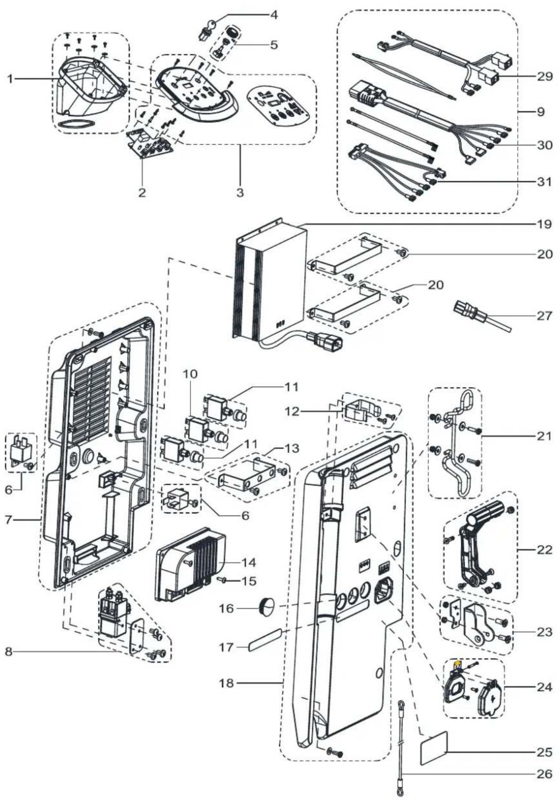
CONTROL SYSTEM AND ELECTRICAL SYSTEM
text_image
Exploded view diagram of a device with numbered parts, showing internal components and assembly relationships.CONTROL SYSTEM AND ELECTRICAL SYSTEM
| Item Part No. Description Qty | |||
| 1 | VS10117 PCB BOX KIT 1 | ||
| 2 | VS10250 CONTROL PANEL BOARD 1 | ||
| 3A | VS10118 CONTROL PANEL WITHOUT TRACTION 1 | ||
| 3B | VS11102 CONTROL PANEL WITH TRACTION 1 | ||
| 4 | 9100001354 KEY SWITCH 1 | ||
| 5B | VS10120 ADJUST SPEED KNOB KIT 1 | ||
| 6 | VS10230 RELAY KIT 2 | ||
| 7 | VS10121 CONTROL BOX BOTTOM KIT 1 | ||
| 8 | VS10231 ELECTROM MAGNETIC SWITCH KIT 1 | ||
| 9A | VS10234 HARNESS MACHINE KIT WITHOUT TRACTION 1 | 1 | |
| 9B | VS11203 HARNES S MACHINE KIT WITH TRACTION 1 | ||
| 10B | VS11201 CIRCUIT BREAKER KIT WITH TRACTION 1 | ||
| 11 | VS10232 CIRCUIT BREAKER KIT 2 | ||
| 12 | VF90275 CLAMP DRAIN HOSE KIT 1 | 1 | |
| 13 | VS10122 FIX BRACKET KIT 1 | ||
| 14B | VS10209 ELECTRONIC BOARD WITH TRACTION SYSTEM 1 | ||
| 15 | VA80758 SCREW PA4x16 4 2 | ||
| 16A | VF85128 CAP BLACK 1 | 1 | |
| 17A | VS10002 RESET LABEL WITHOUT TRACTION 1 | ||
| 17B | VS11002 RESET LABEL WITH TRACTION 1 | ||
| 18 | VS10124 CONTROL BOX COVER KIT 1 | ||
| 19 | VS10240 CHARGER 24V 10A 0 1 | ||
| 19^* | VS10260 CHARGER 24V 13A 1 | ||
| 20 | VS10125 CHARGER FIX BRACKET KIT 2 | ||
| 21 | VF90280 CABLE SUPPORT KIT 1 | 1 | |
| 22 | VF90277 HANDLE LIFT KIT 1 | 1 | |
| 23 | VF90276 HAND BRACKET KIT 1 | 1 | |
| 24 | VS10126 CHARGER SOKET KIT 1 | ||
| 25 | N/A | ||
| 26 | VS10502 CABLE SQUEEGEE LIFT E 1 | ||
| 27 | VF89724 BATTERY CHARGING CABLE US 1 | 1 | |
| 28 | N/A | ||
A: ONLY FOR MACHINE WITHOUT TRACTION
B : ONLY FOR MACHINE WITH TRACTION
CONTROL SYSTEM AND ELECTRICAL SYSTEM
| 29 | VS10212 HARNESS BRUSH METER 1 | ||
| 30A | VS10217 HARNESS CONNECTER WITHOUT TRACTION 1 | ||
| 30B | VS10207 HARNESS CONNECTER WITH TRACTION 1 | ||
| 31A | VS10218 | HARNESS CONTROL CIRCUIT WITHOUT TRACTION | 1 |
| 31B | VS10208 | HARNESS CONTROL CIRCUIT WITH TRACTION 1 | |
A: ONLY FOR MACHINE WITHOUT TRACTION
B : ONLY FOR MACHINE WITH TRACTION
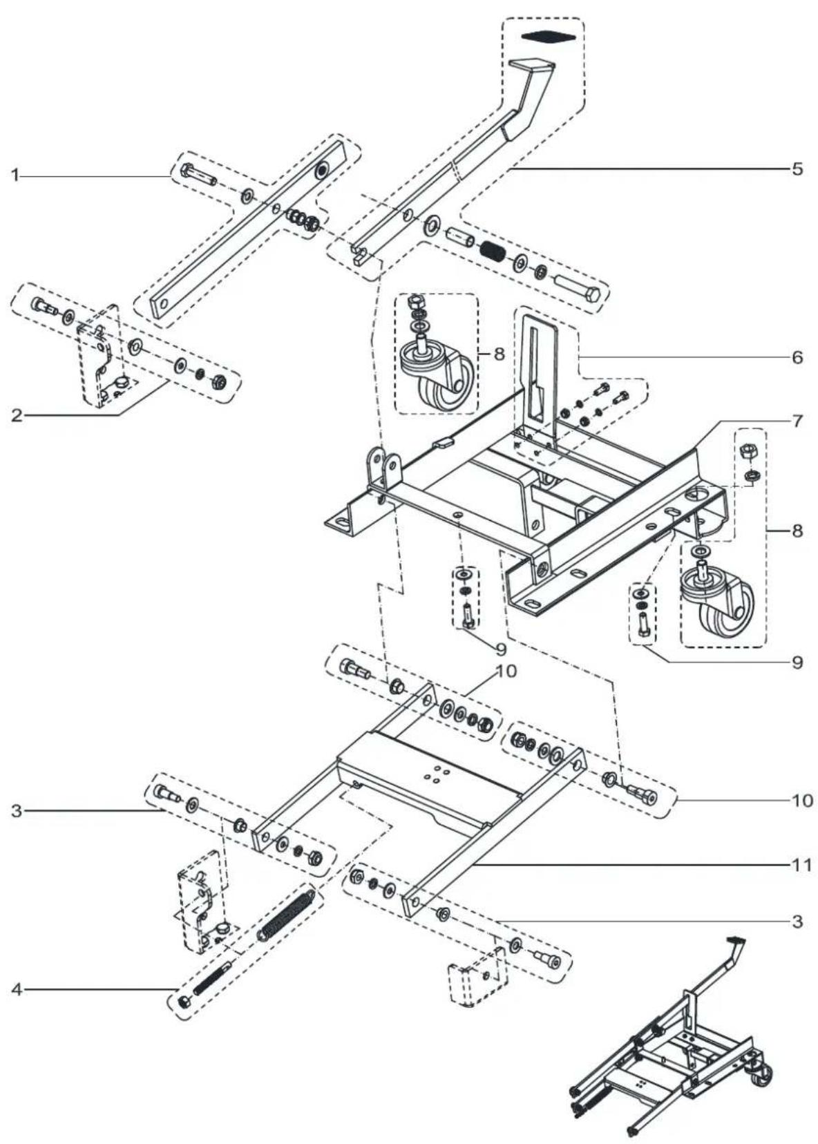
CHASSIS ASSEMBLY
text_image
Exploded view diagram of a mechanical assembly with numbered parts for identificationCHASSIS ASSEMBLY
| Item Part No. Description Qty | |||
| 1 | VS10138 FRONT PEDAL BRUSH LIFTING KIT 1 | ||
| 2 | VS10134 SCREW KIT-1 1 | ||
| 3 | VS10136 SCREW KIT-3 2 | ||
| 4 | VS10139 SPRING KIT 1 | ||
| 5 | VS10140 BACK PEDAL BRUSH LIFTING KIT 1 | ||
| 6 | VS10141 PEDAL SUPPORT KIT 1 | ||
| 7 | VS10406 CHASSIS 1 | ||
| 8 | VS10142 3 INCH CASTER KIT 2 | ||
| 9 | VS10135 SCREW KIT-2 1 | ||
| 10 | VS10137 SCREW KITG4 2 | ||
| 11 | VS10404 BRUSH LIFTING SUPPORT 1 | ||
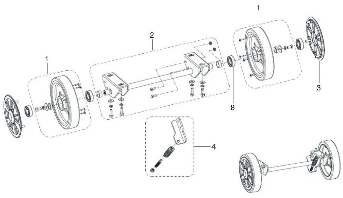
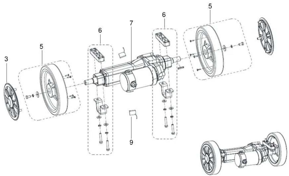
WHEEL ASSEMBLY (WITHOUT TRACTION)
text_image
Exploded view diagram of a mechanical assembly with numbered components and exploded viewsWHEEL ASSEMBLY (WITH TRACTION)
text_image
Technical diagram of a mechanical assembly with numbered components, showing exploded and assembled views of a motor or gear system.WHEELS ASSEMBLY
| Item Part No. Description Qty | |||
| 1 | VS10143 8 INCH | WHEEL WITHOUT TRACTION KIT 2 | |
| 2 | VS10144 WHEEL | SHAFT FIXED PLATE KIT 1 | |
| 3 | VS10330 WHEEL | -COVER 4 | |
| 4 | VS10145 SPRING | KIT 1 | |
| 5 | VS11103 8 INCH | WHEEL WITH TRACTION KIT 2 | |
| 6 | VS10147 TRACTION | MOUNT KIT 2 | |
| 7 | VS11702 MOTOR | TRACTION 1 | |
| 8 | VF14075 BEARING | 6004RS 4 | |
| 9 | VS11703 CARBON | BRUSH KIT 2 | |
SOLUTION ASSEMBLY
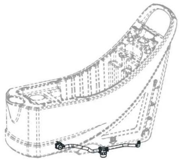
natural_image
Technical line drawing of a mechanical component with internal cavities and mounting holes (no text or symbols)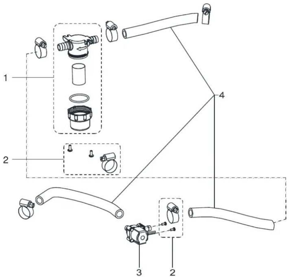
text_image
Technical diagram of a mechanical assembly with labeled parts and exploded viewsSOLUTION ASSEMBLY
| Item Part No. Description Qty | |||
| 1 | VF90621 FILTER KIT 1 | ||
| 2 | VS10148 SCREW AND CLAMP KIT 1 | ||
| 3 | VF90282 SOLENOID VALVE 1 | ||
| 4 | VS10149 TUBE KIT 1 | ||
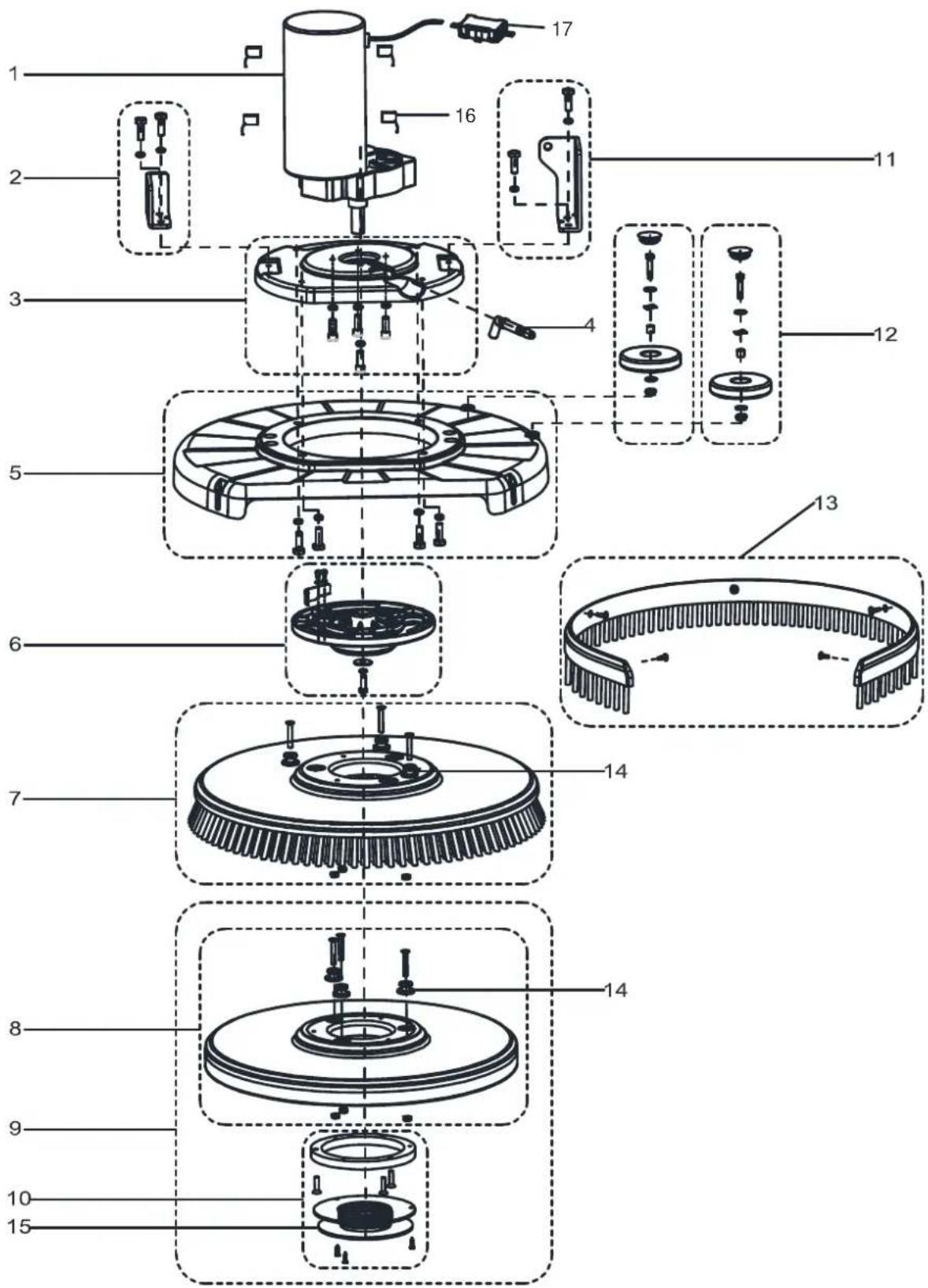
BRUSH ASSEMBLY
text_image
Exploded view diagram of a mechanical assembly with numbered parts for identificationBRUSH ASSEMBLY
| Item Part No. Description Qty | |||
| 1 | VS10702 BRUSH MOTOR KIT 1 | ||
| 2 | VS10132 SHORT CONNECTION PLATE KIT 1 | ||
| 3 | VS10128 MOTOR FIXING PLATE KIT 1 | ||
| 4 | VS10337 ELBOW 1 | ||
| 5 | VS10129 BRUSH DECK KIT 1 | ||
| 6 | VS10130 PLATE DRIVE KIT 1 | ||
| 7* | VF90417 20 INCH BRUSH 1 | ||
| 8 | VF90416 20 INCH PAD 1 | ||
| 9 | VF90454 20 INCH PAD WITH RETAINER 1 | ||
| 10 | VS10131 RETAINER PAD KIT 1 | ||
| 11 | VS10127 LONG CONNECTION PLATE KIT 1 | ||
| 12 | VS10133 BUMPER ROLLER KIT 2 | ||
| 13 | VS10151 SKIRT KIT T 1 | ||
| 14 | VF90469 STUD 3 | 3 | |
| 15 | VF99003A RETAINER PAD 1 | 1 | |
| 16 | VF89116 CARBON BRUSH KIT 4 | ||
| 17 | VR27100 WATERPROOF CASE 1 | 1 | |
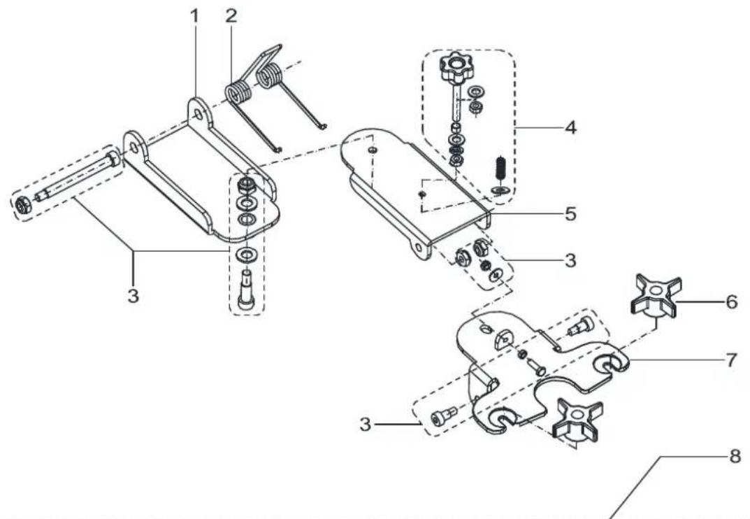
SQUEEGEE ASSEMBLY
text_image
Technical diagram of a mechanical assembly with numbered components for identification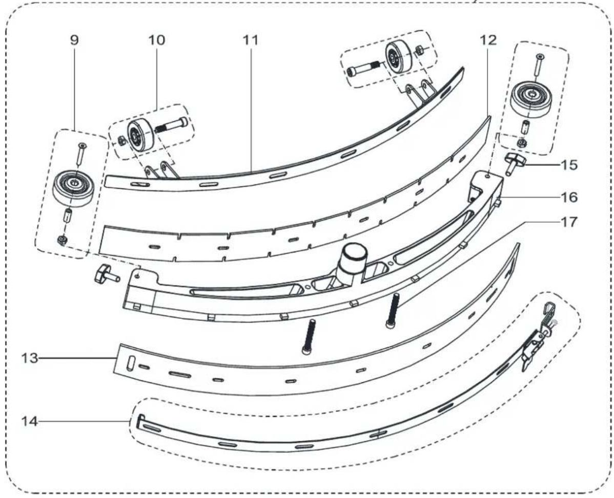
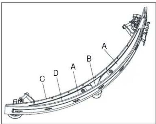
text_image
Technical diagram of a curved mechanical component with numbered parts, likely for assembly or manufacturing purposes.SQUEEGEE ASSEMBLY
| Item Part No. Description Qty | |||
| 1 | VS10401 FRONT-SQUEEGEE-SUPPORT 1 | ||
| 2 | VF82172 | SPRING 70° | 1 |
| 3 | VS13711 HARDWARE SQUEEGEE SUPPORT KIT 1 | ||
| 4 | VF90141 | HAND WHEEL KIT 1 | |
| 5 | VF90110 BACK-SQUEEGEE-SUPPORT 1 | ||
| 6 | VF81210 KNOB 2 | ||
| 7 | VF90109 SQUEEGEE-SUPPORT 1 | ||
| 8 | VF90135 20 INCH SQUEEGEE KIT 1 | ||
| 9 | VF90137 BUMPER ROLLER KIT 2 | ||
| 10 | VF90136 SQUEEGEE ROLL WHEEL KIT 2 | ||
| 11 | VF90118 | 20 INCH STRAP, SQUEEGEE FRONT | 1 |
| 12 | VF90119 20 INCH BLADEFRONT NR 1 | ||
| 12* | VF90148 20 INCH BLADEFRONT PU 1 | ||
| 13 | VF90120 20 INCH BLADE REAR NR 1 | ||
| 13* | VF90149 20 INCH BLADE REAR PU 1 | ||
| 14 | VF90139 20 INCH STRAP T , SQUEEGEE BACK KIT 1 | ||
| 15 | VF85420 WING NUT M8x30 x 2 | ||
| 16 | VF90117 SQUEEGEE 20 INCH I 1 | ||
| 17 | VF90127 SQUEEGEE SCREW M8x65 W 2 | ||
WEAR AND TEAR PARTS
| Item Part No. Description Qty | |||
| 1 | VS10603 DRAIN HOSE GASKET 1 | ||
| 2 | VS10601 SUCTION HOSE 1 | ||
| 3 | VS10102 FILTER COVER KIT 1 | ||
| 4 | VS10202 SWITCH 3 | ||
| 5 | VS10109 WATER LEVEL PIPE KIT 1 | ||
| 6 | VF90536 OUTLET COVER KIT 1 | ||
| 7 | VS10110 ELBOW ADAPTOR KIT 1 | ||
| 8 | VF90534 FLOAT KIT 1 | ||
| 9 | VF90520 VACUUM MOTOR 1 | ||
| 10 | VF90504 GASKETA 1 | ||
| 11 | VS10114 CONNECTION FRAME KIT 1 | ||
| 12 | VS10602 DRAIN HOSE 1 | ||
| 13 | VS10250 CONTROL PANEL BOARD 1 | ||
| 14 | 9100001354 KEY SWITCH | 1 | |
| 15 | VS10230 RELAY KIT K 2 | ||
| 16 | VS10231 ELECTROMAGNETIC SWITCH KIT 1 | ||
| 17A | VS10234 HARNESS MACHINE KIT WITHOUT TRACTION 1 | ||
| 17B | VS11203 HARNESS MACHINE KIT WITH TRACTION 1 | ||
| 18B | VS11201 CIRCUIT BREAKER KIT WITH TRACTION 1 | ||
| 19 | VS10232 CIRCUIT BREAKER KIT 1 | ||
| 20B | VS10209 ELECTRONIC BOARDBWITH TRACTION SYSTEM 1 | ||
| 21 | VS10240 CHARGER 24V 10A 1 1 | ||
| 22 | VS10502 CABLE SQUEEGEE LIFT E 1 | ||
| 23 | VS10142 3 INCH CASTER KIT K 2 | ||
| 24A | VS10143 8 INCH WHEEL WITHOUT TRACTION KIT 2 | ||
| 25B | VS11103 8 INCH WHEEL WITH TRACTION KIT 2 | ||
| 26B | VS11702 MOTOR TRACTION 1 1 | ||
| 27 | VF90621 FILTER KIT 1 | ||
| 28 | VF90282 SOLENOID VALVE 1 | ||
| 29 | VS10702 BRUSH MOTOR KIT 1 | ||
| 30 | VS10337 ELBOW 1 | ||
| 31 | VF90417 20 INCH BRUSH 1 | ||
| 32 | VF90454 20 INCH PAD WITH RETAINER 1 1 | ||
| 33 | VS10133 BUMPER ROLLER KIT 2 | ||
A : ONLY FOR MACHINE WITHOUT TRACTION
B: ONLY FOR MACHINE WITH TRACTION
WEAR AND TEAR PARTS
| 34 | VF90141 | HAND WHEEL KIT 1 | |
| 35 | VF81210 KNOB 2 | ||
| 36 | VF90137 BUMPER ROLLER KIT 2 | ||
| 37 | VF90136 SQUEE GEE ROLL WHEEL KIT 2 | ||
| 38 | VF90119 20 INCH BLADE FRONT NR 1 | ||
| 39 | VF90120 20 INCH BLADE REAR NR 1 | ||
| 40 | VF85420 WING NUT M8x30 2 |
VIPER
Nilfisk Inc.
9435 Winnetka Avenue North
Minneapolis, MN 55445
www.usviper.com