VHC110 - Compressor NILFISK - Free user manual and instructions
Find the device manual for free VHC110 NILFISK in PDF.
| Product type | Compressed air vacuum cleaner |
| Brand | Nilfisk |
| Model | VHC110 |
| Dimensions (L × W × H) | 570 × 560 × 1015 mm |
| Weight | 37 kg |
| Power source | Compressed air |
| Max supply pressure | 6 bars |
| Nominal air consumption (at 6 bars) | 630 NL/min |
| Tank capacity | 37 L |
| Max air flow (3 m hose, ∅ 50 mm) | 115 m³/h |
| Max suction (at 6 bars) | 340 mbar |
| Primary filter area | 1.60 m² |
| Absolute filter area (HEPA H14) | 1.60 m² |
| Absolute filter efficiency (MPPS) | 99.995% (H14) |
| Suction inlet diameter | 50 mm |
| Permitted hose diameters | 40 / 50 mm |
| Sound pressure level (Lpf) | 71 dB(A) |
| Vibrations (ah) | ≤ 2.5 m/s² |
| Intended use | Commercial (hotels, schools, hospitals, factories, etc.) |
| Suction types | Dry and liquid substances (with mechanical stop) |
| Filter cleaning system | Manual (shaker) |
| Safety devices | Emergency stop, vacuum gauge, mechanical liquid stop |
| Routine maintenance | Filter cleaning, tank draining, bag/filter replacement |
| Operating temperature | -10 °C to +40 °C |
| Operating humidity | ≤ 85% |
Frequently Asked Questions - VHC110 NILFISK
User questions about VHC110 NILFISK
0 question about this device. Answer the ones you know or ask your own.
Ask a new question about this device
Download the instructions for your Compressor in PDF format for free! Find your manual VHC110 - NILFISK and take your electronic device back in hand. On this page are published all the documents necessary for the use of your device. VHC110 by NILFISK.
USER MANUAL VHC110 NILFISK
natural_image
Line drawing of a vacuum cleaner with wheels and control panel (no text or symbols)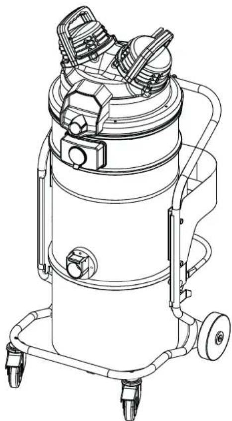
natural_image
Technical line drawing of a vacuum cleaner with attached gauges and wheels (no text or symbols)Translation of the original instructions
Table of contents
Instructions for use....2
Operator's safety 2
General information for using the machine 2
Proper uses 2
Improper Use....2
Testing and guarantee.... 3
How to request assistance .... 3
Exclusion of liability 3
Versions and variations 3
General recommendations....3
Residual Risks....4
EC Declaration of conformity....4
Description of the machine ....5
Machine Parts and Labels....5
Optional kits....5
Accessories 5
Packing and unpacking 5
Unpacking, moving, use and storage 5
Setting to work - connection to the pneumatic system 6
Supply pressure adjustment....6
Dry applications....7
Vacuuming of liquids 7
Technical data 8
ATEX Variant Technical Data....9
Dimensions....9
Controls and indicators.... 10
Inspections prior to starting 10
Starting and stopping 10
Emergency stopping.... 10
Operation....10
Maintenance, cleaning and decontamination....11
Filter cleaning....11
Container and dust bag cleaning.... 12
Dust bag replacement 12
Primary and absolute filter replacement.... 13
Installation, cleaning and replacement of the separator (optional).... 14
Tightness inspection.... 15
Recommended spare parts ....16
Troubleshooting....17
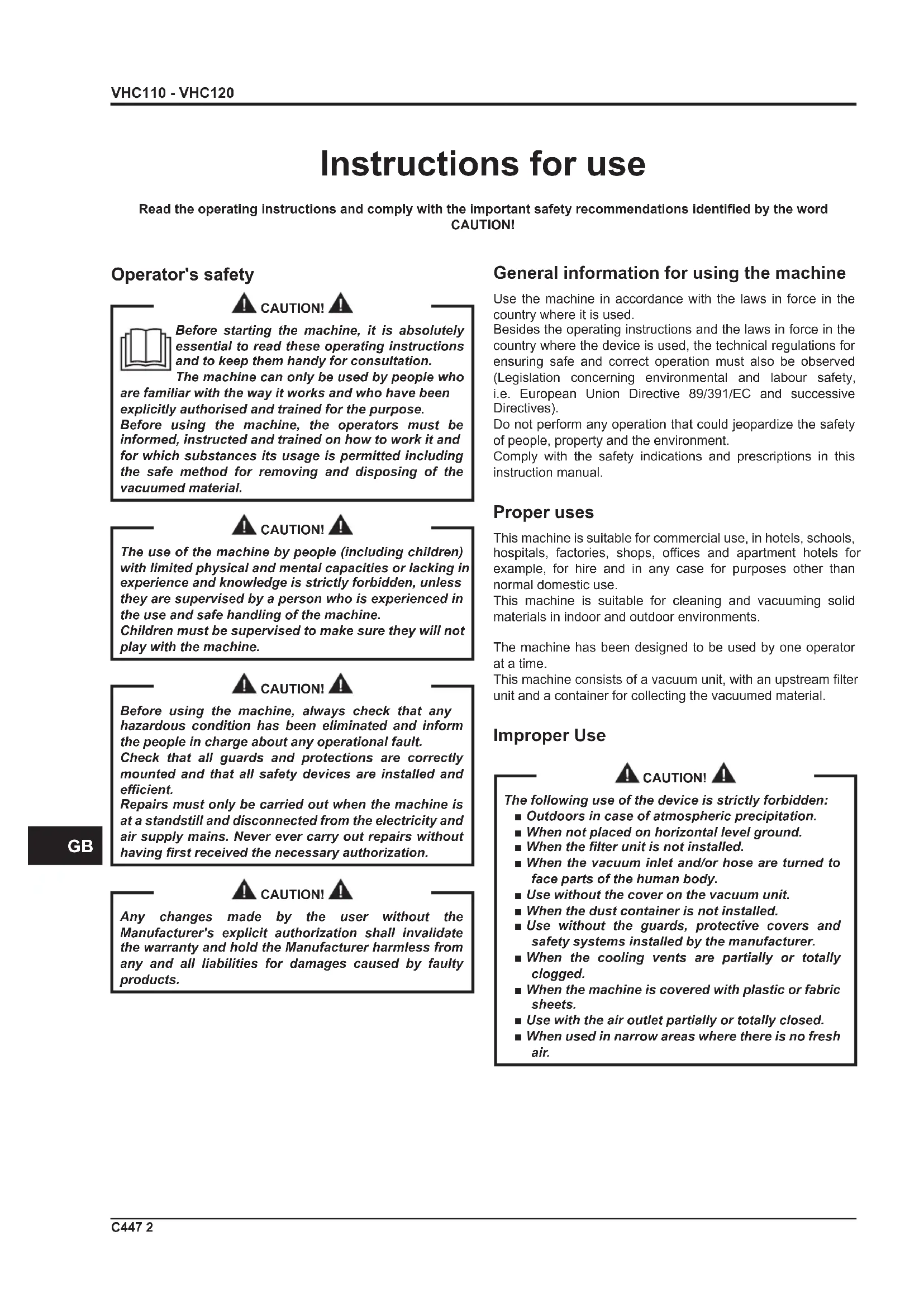
Instructions for use
Read the operating instructions and comply with the important safety recommendations identified by the word CAUTION!
Operator's safety

CAUTION!


Before starting the machine, it is absolutely essential to read these operating instructions and to keep them handy for consultation.
The machine can only be used by people who are familiar with the way it works and who have been explicitly authorised and trained for the purpose.
Before using the machine, the operators must be informed, instructed and trained on how to work it and for which substances its usage is permitted including the safe method for removing and disposing of the vacuumed material.

CAUTION!

The use of the machine by people (including children) with limited physical and mental capacities or lacking in experience and knowledge is strictly forbidden, unless they are supervised by a person who is experienced in the use and safe handling of the machine.
Children must be supervised to make sure they will not play with the machine.

CAUTION!

Before using the machine, always check that any hazardous condition has been eliminated and inform the people in charge about any operational fault.
Check that all guards and protections are correctly mounted and that all safety devices are installed and efficient.
Repairs must only be carried out when the machine is at a standstill and disconnected from the electricity and air supply mains. Never ever carry out repairs without having first received the necessary authorization.

CAUTION!

Any changes made by the user without the Manufacturer's explicit authorization shall invalidate the warranty and hold the Manufacturer harmless from any and all liabilities for damages caused by faulty products.
General information for using the machine
Use the machine in accordance with the laws in force in the country where it is used.
Besides the operating instructions and the laws in force in the country where the device is used, the technical regulations for ensuring safe and correct operation must also be observed (Legislation concerning environmental and labour safety, i.e. European Union Directive 89/391/EC and successive Directives).
Do not perform any operation that could jeopardize the safety of people, property and the environment.
Comply with the safety indications and prescriptions in this instruction manual.
Proper uses
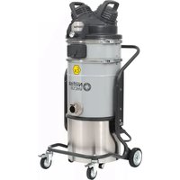
This machine is suitable for commercial use, in hotels, schools, hospitals, factories, shops, offices and apartment hotels for example, for hire and in any case for purposes other than normal domestic use.
This machine is suitable for cleaning and vacuuming solid materials in indoor and outdoor environments.
The machine has been designed to be used by one operator at a time.
This machine consists of a vacuum unit, with an upstream filter unit and a container for collecting the vacuumed material.
Improper Use

CAUTION!

The following use of the device is strictly forbidden:
■ Outdoors in case of atmospheric precipitation.
■ When not placed on horizontal level ground.
■ When the filter unit is not installed.
■ When the vacuum inlet and/or hose are turned to face parts of the human body.
■ Use without the cover on the vacuum unit.
■ When the dust container is not installed.
■ Use without the guards, protective covers and safety systems installed by the manufacturer.
■ When the cooling vents are partially or totally clogged.
■ When the machine is covered with plastic or fabric sheets.
■ Use with the air outlet partially or totally closed.
■ When used in narrow areas where there is no fresh air.
CAUTION!
The following use of the device is strictly forbidden:
■ When the cable or plug is damaged. If appliance is not working as it should, has been dropped, damaged, left outdoors or dropped into water, return it to an authorized service center.
■ Vacuuming liquids with machine not equipped with specific original stopping systems.
- Do not pull or carry by the cord, use the power cord as a handle, do not close a door on cord, or pull cord around sharp edges or corners. Do not run the appliance over the cord. Keep cord away from heated surfaces.
■ Vacuuming the following materials:
- Burning materials (embers, hot ashes, lit cigarettes, etc.).
- Naked flames.
- Combustible gas.
- Flammable liquids, aggressive fuels (gasoline, solvents, acids, alkaline solutions, etc.).
- Explosive dust/substances and/or ones liable to ignite in a spontaneous way (such as magnesium or aluminium dusts, etc.).
Note: Fraudulent use is not admitted.
Testing and guarantee
■ Testing
Each machine is subjected to a final test involving its operation and performances. This guarantees maximum efficiency during the work the machine must carry out.
■ Warranty
The guarantee clauses are specified in the sales contract.
How to request assistance
In the event of faults or malfunctions requiring the intervention of specialized technicians, contact the Manufacturer or your nearest After-Sales Service Centre.
Exclusion of liability
The machine was delivered to the user according to the conditions valid at the time of purchase.
For no reason what so ever shall the user be authorized to tamper with the machine.
Contact your nearest After-Sales Service Centre in the event of faults.
All attempts by the user or by unauthorized personnel to demount, modify or, more generally, tamper with any part of the machine shall void the guarantee and relieve the manufacturer of all responsibility for damage to either persons or property caused by such action.
The manufacturer shall also be relieved of liability in the following cases:
■ Incorrect installation.
■ Improper use of the machine by inadequately trained personnel.
■ Utilization contrary to the provisions in force in the country of use.
■ Incorrect or insufficient maintenance.
■ Use of non-genuine spares or use of spares that are not specifically made for the model in question.
■ Total or partial failure to comply with the instructions.
■ Failure to forward the warranty certificate.
■ Exceptional environmental events
Versions and variations
ATEX variations (Z21 - Z1)
[ NOTE ]
Refer to the manufacturer's sales network for these versions.
For ATEX devices see the instructions for "ATEX" use.
The manufacturer produces machines suitable to be used in potentially explosive atmospheres. These variants are manufactured according to directives and standards in force. The relevant additional instructions are supplied together with the machine.
HEPA variations (AU)
This machine can be equipped with a filter (HEPA). The procedures for servicing and emptying the machine including removing the dust container, must only be performed by authorized personnel wearing protective clothing. Do not use without the complete filter system in place.
General recommendations
CAUTION!
If an emergency situation occurs:
■ for example, accident - fault - filter breakage - fire - etc.
Disconnect the machine from the power supply and ask for assistance from qualified personnel.
In case the user comes into contact with the vacuumed product, check the cautions shown on the safety technical sheet of the product, which must be made available from the employer.
[ NOTE ]
Check the place of work and substances tolerated for the machine suitable for liquids.
CAUTION!
The machines must not be used or stored outdoors, or in damp places.
Only versions with the level sensor can be used for liquids, if not, they can only be used to vacuum dry materials.

CAUTION!

Version for liquids.
If foam or liquid leaks out of the machine, turn it off immediately and contact qualified personnel for assistance.
[ NOTE ]
These devices must not be used in corrosive environment.
Residual Risks
After carefully considering the risks that are present in all machine operating phases, necessary measures were adopted in order to eliminate the risks for the operators, as far as possible, and/or limit or reduce the risks deriving from hazards that cannot be completely eliminated at the source.
During operations and/or maintenance, operators are exposed to certain residual risks which, due to the nature of the operations themselves, cannot be completely eliminated. Therefore the installer is responsible for providing additional information and/or hazard signals based on the location of machine installation and the material that is handled.
EC Declaration of conformity
Every machine comes with a EC Declaration of conformity. See fac-simile in fig. 17.
[ NOTE ]
The Declaration of conformity is an important document and should be kept in a safe place to be presented to the Authorities on request.
Description of the machine
Machine Parts and Labels
Figure 1
- Identification plate:
Model code, serial number, EC marking, year of manufacture, weight (kg)
- Dust container
- Dust container release lever
- Vacuum inlet
- Castor brake lever
- Handle
- Closing band lever
- Warning plate
Draws the operator's attention to the fact that the filter must only be shaken when the vacuum cleaner is turned OFF (see also par. "Primary filter shaker").
- Pneumatic system connection fitting.
This machine creates a strong air flow which is drawn in through the vacuum inlet and blows out through the outlet.
Before turning on the machine, fit the vacuum hose into the inlet and then fit the required tool on to the end part (refer to the manufacturer's accessory catalogue or Service Centre).
The diameters of the authorized hoses are indicated in the Technical data table.
The machine is equipped with a primary filter which enables it to be used for the majority of applications.
In addition to the primary filter that retains the most common dust, a secondary filter (absolute filter) can be installed.
Figure 2
Appliances intended for use in atmospheres classified as explosive are constructed in accordance with 2014/34/EU Directive (ATEX):
- ATEX label
Optional kits
Various optional kits are available for converting the machine.
On request, the machine can be supplied with optional kits already installed. However, they can also be installed at a later date.
Please contact the sales network for further details.
Instructions describing how to fit the optional kits and the relative operation and maintenance manuals are supplied together with the optional kits.

CAUTION!

Use only supplied and authorised genuine spare parts.
Accessories
Various accessories are available; refer to the manufacturer's accessory catalogue.

CAUTION!

Use only genuine accessories supplied and authorised by the manufacturer.
Packing and unpacking
All the dispatched equipment has been thoroughly checked before being delivered to the haulage contractor.
On arrival, check the machine to see that it has not been damaged during transport. In case of damage, immediately lodge a complaint with the haulage contractor.
Dispose of the packing materials in compliance with the laws in force.
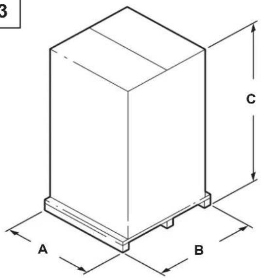
Figure 3
| Model A (mm) | B (mm) C | (mm) kg (*) | ||
| VHC110 - VHC120 7 | 00 790 1500 | 55 |
(*) Weight with packing
Unpacking, moving, use and storage
To unpack the vacuum unit, remove the retainers with a hammer and a screwdriver.
Also remove the fastening devices placed by the manufacturer when packing, by using suitable tools.
Release the wheel brakes and remove the machine from the supporting platform, by using a ramp that can provide adequate capacity, and by driving the vacuum cleaner by the handle.
Operate on flat, horizontal surfaces.
The load-bearing capacity of the surface the machine is placed on must be suitable for bearing its weight.
If the device is to work in a fixed position, allow wide space around the device in order to ensure freedom of the movement and allow the maintenance staff to operate with ease.

CAUTION!

The manufacturer shall not be liable for any damages caused to the machine during lifting, when the lifting equipment supplied by the manufacturer is not used.

CAUTION!

When several supporting platforms are provided, the supporting platform to which the machine is anchored must be handled with a forklift truck that can provide adequate capacity. Then unpack the machine by laying it down on a flat and horizontal surface that can provide adequate capacity for the vacuum cleaner weight.
Setting to work - connection to the pneumatic system

CAUTION!

■ Make sure there is no evident sign of damage to the machine before starting work.
■ Before connecting the machine to the pneumatic supply, make sure the network supplies condensate-free air at the pressure indicated in this manual (see technical data).
■ Regularly check there are no signs of damage, excessive wear, cracks or ageing on the connecting hose.

CAUTION!

When the device is operating, do not:
■ Crush, pull, damage or tread on the connecting hose.
■ Only replace the supply hose with one of the same type as the original.
Those responsible for plant safety must ensure that:
■ Prevent any improper use or manoeuvre.
■ Make sure that the safety devices are not removed or tampered with.
■ Check that all maintenance operations are regularly performed;
■ Make sure that no machine part (couplings, holes, etc.) is modified to attach additional devices;
■ Make sure that only original Nilfisk spare parts are used.
NOTE
The user shall be responsible for ensuring that installation complies with the all relevant local provisions. The equipment must be installed by qualified technicians who have read and understood the instructions herein.

CAUTION!

The air plant must have a filter/reducer since the air that reaches the solenoid valves must be filtered. The air pressure must be between a maximum 6 bar and a minimum 4 bar.
Supply pressure adjustment
The machine is equipped with a pressure governor only in case the pressure governor optional has been purchased.

CAUTION!

If the adjustment procedure below is not properly respected in each step or if the knob is forced excessively in the direction of the maximum pressure (clockwise), there is a risk of damage to the device and the operator's safety can be compromised.
- Adjust the pressure as required, according to the compressor performances.
- In order to ensure proper performance of the machine, check that the supply piping diameter is adequate, that is to say not less than a nominal diameter of 14 mm.
- Connect the machine to the air supply, then open the on/off valve.
For models equipped with pressure regulator
-
Adjust the supply air pressure as follows:
-
Turn the pressure regulator knob in the direction of the minimum pressure (counter-clockwise) up to the limit switch (regulator closed)
- Turn the air regulator knob in the direction of the maximum pressure (clockwise) until it reaches the desired pressure, and check that it remains stable for at least 3 minutes; press the knob to lock it.
NOTE
If the clockwise rotation reaches the end of the stroke without having reached the desired pressure, and the conditions in point 1 and 2 are met, set a lower supply pressure (see table 1) and repeat the procedure starting from step "a".
| Pressure (Bar) | Consumption (NL/min) | Capacity ( m^3/h ) | Vacuum (mbar) |
| VHC110 | |||
| 4 450 110 | 250 | ||
| 5 540 115 | 320 | ||
| 6 630 115 | 340 | ||
| VHC120 | |||
| 4 900 | 180 | 235 | |
| 5 | 1080 | 200 | 300 |
| 6 | 1260 | 200 | 320 |
With vacuum hose length: 3m , diameter: 50~mm
Dry applications
[ NOTE ]
The supplied filters and the bag (if applicable) must be installed correctly.
![NILFISK VHC110 - [ NOTE ] - 1](/content/2026/04/638455/images/c9f9be9dc2fbabba606cfc08510135ad600f83102771eb3bf546f56e25acf5f1.jpg)
Comply with the safety regulations governing the vacuumed materials.
Vacuuming of liquids

Comply with the safety regulations governing the vacuumed materials.
■ Make sure the liquid stop device is working correctly before vacuuming liquids.
■ In case of foam, immediately stop working, turn off the machine and empty the container.
■ Regularly clean the liquid level limiting device and check to make sure that there are no signs of damage.
■ Dirty liquid vacuumed by the machine must be considered conductive.
Do not use the machine if the liquid mechanical stop is not installed! If it's used without the float, the machine may be seriously damaged.
When vacuuming a mix of water and air, take care to avoid overloading the motor of the vacuum unit.
The machine vacuums liquids and deposits them into the container.
When the machine vacuums liquids it must be equipped with liquid mechanical stop.
The liquid mechanical stop does not automatically stop the vacuum. When the liquid container is full, switch off the machine and empty the liquid container.
Technical data
| Parameter | Units of measurement | VHC110 VHC120 | |
| Maximum supply pressure (****) bar 6 | |||
| Air consumption (***) (****) NL/min | 630 1.260 | ||
| Compressed air junction mm 14 19 | |||
| Max vacuum (***(****) mBar | 340 320 | ||
| Maximum air flow rate without hose and reductions (***) (****) | m^3/h 130 | 225 | |
| Maximum air flow rate (3 m ∅ 50 mm hose) (***) (****) | m^3/h 115 | 200 | |
| Sound pressure level (Lpf) (EN60335-2-69) (*) | dB(A) 71 | 72 | |
| Vibration, ah (**) | m/s^2 | ≤2,5 | |
| Container capacity | L | 37 | |
| Vacuum inlet (diameter) | mm | 50 | |
| Allowed hoses | mm | 40 / 50 | |
| Primary filter surface | m^2 | 1,60 | |
| Upstream absolute filter surface m | ^2 | 1,60 | |
| Absolute filter efficiency according to MPPS method (EN 1822) | % | 99,995 (H14) | |
(*) Measurement uncertainty KpA < 1.5 dB(A). Noise emission values obtained according to EN-60335-2-69
(**) Total value of vibration output to the operator arm and hand
(***) With supply pressure of 6 bar
(****) See paragraph "Adjusting the supply pressure"
ATEX Variant Technical Data
| Parameter | Units of measurement | VHC110 Z1 VHC120 Z1 | |
| Maximum supply pressure (****) bar 6 | |||
| Air consumption (***) (****) NL/min | 630 1.260 | ||
| Compressed air junction mm | 14 | 19 | |
| Max vacuum (***(****) | mBar | 340 | 320 |
| Maximum air flow rate without hose and reductions (***) (****) | m^3/h | 130 | 225 |
| Maximum air flow rate (3 m ∅ 50 mm hose) (***) (****) | m^3/h | 115 | 200 |
| Sound pressure level (Lpf) (EN60335-2-69) (*) | dB(A) | 71 | 72 |
| Vibration, ah (**) | m/s^2 | ≤2,5 | |
| Container capacity | L | 37 | |
| Vacuum inlet (diameter) | mm | 50 | |
| Allowed hoses | mm | 40 / 50 | |
| Primary filter surface | m^2 | 1,60 | |
| Upstream absolute filter surface m | ^2 | 1,60 | |
| Absolute filter efficiency according to MPPS method (EN 1822) | % | 99,995 (H14) | |
(*) Measurement uncertainty KpA < 1.5 dB(A). Noise emission values obtained according to EN-60335-2-69
(**) Total value of vibration output to the operator arm and hand
(***) With supply pressure of 6 bar
(****) See paragraph "Adjusting the supply pressure"
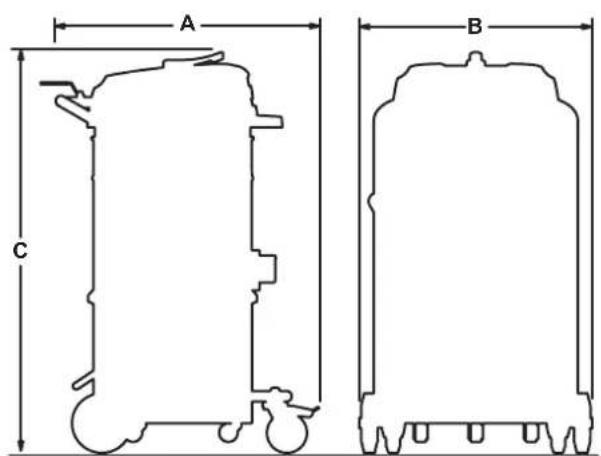
Dimensions
Figure 4
| Model | VHC110VHC120 | VHC110 Z1VHC120 Z1 |
| A (mm) 570 | ||
| B (mm) 560 | ||
| C (mm) 1015 1240 | ||
| Weight (kg) 37 | ||
[ NOTE ]
■ Storage conditions:
Temperature: -10^ ÷ +40^
Humidity: ≤ 85%
■ Operating conditions:
Maximum altitude: 800 m
(Up to 2,000 m with reduced performances)
Temperature: -10^ ÷ +40^
Humidity: ≤ 85%
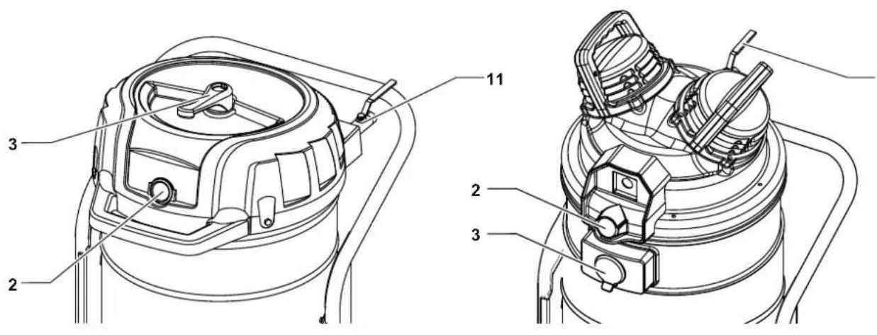
Controls and indicators
Figure 5
- On/Off valve
- Pressure regulator
- Filter cleaning system
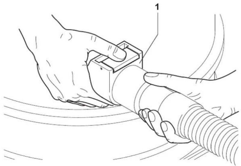
Inspections prior to starting
Figure 6
Before starting, check that:
■ The filters are installed.
■ The closing band is properly tightened.
■ The vacuum hose and tools have been correctly fitted into the vacuum inlet (1).
■ In case of liquid application, the liquid mechanical stop is properly installed inside the liquid container:
■ The bag or safety container is installed, if applicable.

CAUTION!

Do not use the device if the filters are faulty.
Starting and stopping
Figure 5

CAUTION!

Before starting the machine, lock the castor brakes
■ Open the valve (1) to start vacuuming.
■ Close the valve (1) to stop vacuuming.
Machines equipped with system for vacuuming liquids
■ When the container is full, the liquid mechanical stop turns off the vacuuming; the vacuum unit remains on.
■ Do not let the vacuum unit running, after the liquid stop has been activated. Turn it off.
Emergency stopping
Close the on/off valve. The machine stops.
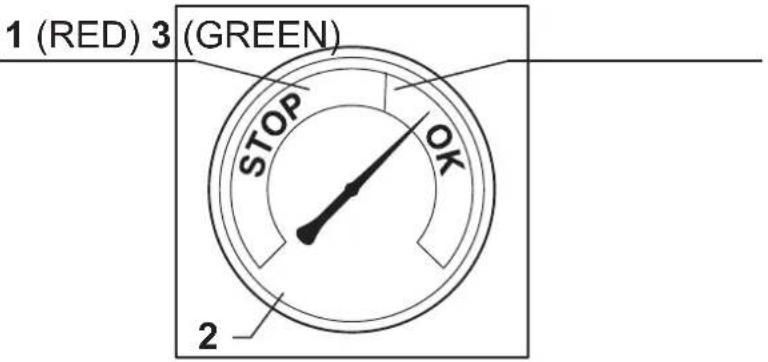
Operation
Figure 7
Vacuum gauge (2): green zone (3), red zone (1)
When using the machine, check the flow control:
■ when the machine is operating, the pointer of the vacuum gauge must remain in the green zone (3) to ensure that the speed of the intake air does not drop below the safety value of 20 m/sec;
■ If the pointer is in the red zone (1) it means that the speed of the air in the vacuum hose is less than 20 m/s, and that the machine is not operating in optimal conditions. Shake or replace the filter.
■ during normal operation conditions, close the vacuum hose, the pointer of the vacuum gauge must switch from the green zone (3) to the red zone (1).

CAUTION!

The air speed in the vacuum hose must not be less than 20 m/s. Condition indicated by the vacuum gauge pointer in the green zone (3).

CAUTION!

All machines can be used only with hoses whose diameters comply with the specifications in the "Technical Data" table.

CAUTION!

Consult the "Troubleshooting" chapter if faults occur.
At the end of a cleaning session
■ Close the on/off valve to stop vacuuming.
■ Wind up the connection cable.
■ Empty the container and clean the vacuum cleaner as described in the “Maintenance, cleaning and decontamination” paragraph.
■ Wash the container with clean water if aggressive substances have been vacuumed.
■ Store the machine in a dry place, out of reach of unauthorised people.
■ Lock the castor brakes.
■ During transport and when not using the machine, close the vacuum inlet with the relevant plug (if equipped).
Maintenance, cleaning and decontamination
CAUTION!
Disconnect the machine from its power source before cleaning, servicing, replacing parts or converting it to obtain another version/variant.
- Carry out only the maintenance operations described in this manual.
■ Use only original spare parts.
■ Do not modify the machine in any way.
Failure to comply with these instructions could jeopardize your safety. Moreover, such action would immediately void the EC declaration of conformity/ incorporation issued with the machine.
CAUTION!
For maintenance procedures not described in this manual, please contact the manufacturer's technical support or sales network.
CAUTION!
To guarantee the safety level of the machine, only original spare parts supplied by the manufacturer should be used.
CAUTION!
The precautions described below must be taken during all maintenance operations, including cleaning and replacing the primary and absolute filters.
■ To allow the user to carry out the maintenance operations, the machine must be disassembled, cleaned and overhauled as far as is reasonably possible, without causing hazards for the maintenance staff or other people. The suitable precautions include decontamination before disassembling the machine, adequate filtered ventilation of the exhaust air from the room in which it is disassembled, cleaning of the maintenance area, and suitable personal protection.
■ The external parts of the machine must be decontaminated by cleaning and vacuuming methods, dedusted or treated with sealant before being taken out of a hazardous zone.
■ All parts of the machine must be considered as contaminated when they are removed from the hazardous zone and appropriate actions must be taken to prevent dust from dispersing.
■ When maintenance or repair procedure are carried out, all the contaminated elements that cannot be properly cleaned, must be eliminated. These elements must be disposed of in sealed bags in accordance with applicable regulations and local laws on the disposal of such material. This procedure must also be followed for filter disposal (primary and absolute filters).
■ Compartments that are not dust-tight must be opened with suitable tools (screwdrivers, wrenches, etc.) and thoroughly cleaned.
■ A check must be carried out by the manufacturer or the personnel of the same at least once a year. For example: Check the air filters to find out whether the air-tightness of the machine has been impaired in any way and make sure that the electric control panel operates correctly.
Filter cleaning
Primary filter cleaning with manual system (VHC110 - VHC120)
Figure 5
According to the quantity of vacuumed material, if the vacuum gauge pointer (2, Fig. 7) goes from the green zone (3, Fig. 7) to the red zone (1, Fig. 7), shake the primary filter by turning the lever (3, Fig. 5) clockwise/counter-clockwise for at least 5 complete cycles.
CAUTION!
Stop the machine before using the filter shaker. Do not shake the filter with the machine functioning, as this could damage the filter.
Wait before restarting the machine, to allow the dust to settle. Replace the filter element if the indicator is red, even after the filter has been shaken (see "Primary and absolute filters disassembly and replacement").
[ NOTE ]
If the indicator is still in the red area. The vacuum hose or one of the accessories may be clogged, and not the filter. Clean these parts if this is the case.
Primary filter cleaning with manual system (VHC110 Z1 - VHC120 Z1)
Figure 5
According to the quantity of vacuumed material, if the vacuum gauge pointer (2, Fig. 7) goes from the green zone (3, Fig. 7) to the red zone (1, Fig. 7), clean the primary filter by closing the inlet (4, Fig. 1) and by opening the PullClean system flap (3, Fig. 5), repeat the procedure 3 or 4 times, for 1 or 2 seconds each time.
CAUTION!
Perform this procedure with the vacuum cleaner running
Replace the filter element if the indicator is red, even after the filter has been shaken (see "Primary and absolute filters disassembly and replacement").
[ NOTE ]
If the indicator is still in the red area. The vacuum hose or one of the accessories may be clogged, and not the filter. Clean these parts if this is the case.
Container and dust bag cleaning
Emptying the container

CAUTION!

Before proceeding with these operations, turn off the machine and remove the plug from the power socket. Check the machine filtration class.
Before emptying the container it is advisable to clean the filter (see "Cleaning the primary filter" paragraph).
Figure 1
■ Release the dust container (2) with the lever (3), then remove and empty it.
■ Clean the machine as described in the “Maintenance, cleaning and decontamination” paragraph.
■ Wash the container with clean water if aggressive substances have been vacuumed.
■ Make sure the gasket is in perfect condition and correctly positioned.
■ Place the container back in position and secure it again.
[ NOTE ]
After the cleaning session, leave the machine running for at least 60 seconds before turning it off. Avoid switching on/off too frequently.
Emptying of the liquid container

CAUTION!

Before proceeding with these operations, turn off the machine and remove the plug from the power socket. Check the machine filtration class.
Before emptying the container it is advisable to clean the filter (see "Cleaning the primary filter" paragraph).
Figure 1
■ Release the container (2) with the lever (3) and remove it, then remove the liquid stop device and empty it.
- Clean the machine as described in the “Maintenance, cleaning and decontamination” paragraph.
■ Wash the container with clean water if aggressive substances have been vacuumed.
■ Make sure the gasket is in perfect condition and correctly positioned.
■ Place the container back in position and secure it again.
[ NOTE ]
After the cleaning session, leave the machine running for at least 60 seconds before turning it off. Avoid switching on/off too frequently.
[ NOTE ]
The filter element will be wet after liquids have been vacuumed.
A wet filter element can quickly become clogged if the machine is then used to vacuum dry substances.
For this reason, make sure that the filter element is dry or replace it with another one before using the machine for dry materials.
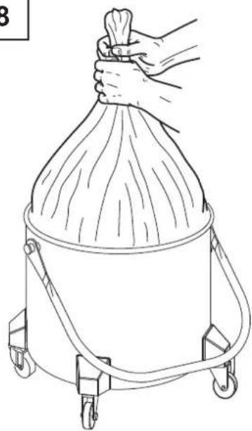
Dust Bag
Figure 8
The machine can be equipped with dust collection bag. In this case, the machine must be equipped with optional accessories (depressor and grid). If the bag is not installed or is installed improperly, it could create health risks for people exposed.
Paper Bag and Safe Bag for dust collection
Figure 9
The machine can be equipped with dust collection bag. In this case, the machine must be equipped with a specific container and a cap on the side. If the bag is not properly installed, it could create health risks for people exposed.
[ NOTE ]
The safe bag system is suitable to collect toxic dust to ensure that the user does not come into contact with the product.
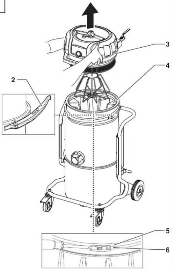
Longopac ^® bag for dust collection
Figure 10
The machine can be equipped with dust collection bag. In this case, the material is discharged by gravity when the vacuuming stops. The Longopac® bag can be cut, sealed or closed to the size required. If the bag is not properly installed, it could create health risks for people exposed.
Dust bag replacement

CAUTION!

■ Before proceeding with these operations, turn off the machine and remove the plug from the power socket.
■ These operations can only be carried out by trained and qualified personnel who must wear adequate clothing, in compliance with the laws in force.
In case of hazardous and/or harmful dust, use only the bags recommended by the manufacturer (see "Recommended spare parts").
■ The bag must only be disposed of by qualified personnel and in compliance with the laws in force.
■ Use only original Nilfisk bags.
■ Only use bags suitable for the machine class you are using.

CAUTION!

Take care not to raise dust during this operation. Wear a P3 mask and other protective clothing plus protective gloves (PPE) suited to the hazardous nature of the dust collected, refer to the laws in force.
How to replace the Dust Bag
Figure 8
■ Close the inlet by using the relevant cap (if equipped).
■ Release the dust container.
■ Remove the dust bag and close it with a clamp, if necessary.
■ Place a new bag, taking care to wrap it around the outer wall of the dust container.
■ Set the dust container into the machine again.
How to replace the Paper Bag
Figure 9
■ Close the inlet by using the relevant cap (if equipped).
■ Release the dust container.
■ Remove the bag and close it with the relevant cap (1) as shown in the figure.
■ Insert a new bag, making sure the bag inlet is sealed.
■ Set the dust container into the machine again.
How to replace the Safe Bag
Figure 9
■ Remove and put the vacuum hose in a safe and dust-free place.
■ Close the inlet by using the relevant cap (if equipped).
■ Release the dust container.
■ Close the Safe Bag by pulling the "guillotine" seal (2).
■ Close the plastic bag hermetically using the relevant band (3).
■ Use the sticky tape (4) to close the bottom of the plastic bag.
■ Remove the relevant connection (5) of the bag from the vacuum inlet.
■ Insert a new safe bag, making sure the vacuum inlet is well connected to the bag attachment, to grant the sealing.
■ Wrap the plastic bag around the dust container external wall.
■ Place the dust container in the vacuum cleaner.
How to replace the Longopac®
Figure 10
■ Turn the bag full of dust (1) on itself to obtain a section of coiled bags to be tightened with two clamps (2).
■ Place the two clamps at a distance of 50 mm between them, then with a pair of scissors cut between the two clamps.
■ Remove the bag full of dust (1) and place the new section of Longopac® (3).
Primary and absolute filter replacement

CAUTION!

When the machine is used to vacuum hazardous substances, the filters become contaminated, therefore:
■ Work with care and avoid spilling the vacuumed dust and/or material;
■ place the disassembled and/or replaced filter in a sealed plastic bag;
■ close the bag hermetically;
■ dispose of the filter in accordance with the laws in force.

CAUTION!

Filter replacement is a serious matter. The filter must be replaced with one of identical characteristics, filtering surface and category.
Otherwise the machine will not operate correctly.
Before proceeding with these operations, turn off the machine and remove the plug from the power socket.

CAUTION!

Before performing these operations, clean the filter as described in the "Maintenance, cleaning and decontamination" paragraph.

CAUTION!

Take care not to raise dust during this operation. Wear a P3 mask and other protective clothing plus protective gloves (PPE) suited to the hazardous nature of the dust collected, refer to the laws in force.

CAUTION!

Reassemble with care to avoid trapping your hands between the vacuum unit and the container. Use gloves that provide protection against mechanical risks (EN 388) with a level of protection CAT. II.

CAUTION!

Do not use the Class H filter again after having removed it from the machine.
GB
Primary filter replacement, for machines equipped with manual cleaning system (VHC110 - VHC120)
Figure 11
■ Release the closing band (2).
■ Remove the deck (3) together with the cage, taking care not lift the primary filter (4).
■ Remove and dispose of the filter according to the laws in force.
■ Reset the vacuum cleaner by inserting a new filter and fastening it on the ring (5) with the metal clamp (6).
■ Install the deck and the cage in the primary filter by taking care that there is one spoke of the cage every two pockets of the star filter.
■ Check the correct position of the filter shaker lever (1).
■ Tighten the closing band (2).
Primary filter replacement, for machines equipped with manual cleaning system (VHC110 Z1 - VHC120 Z1)
Figure 11
■ Release the closing band (2).
■ Remove the head (3).
■ Remove and dispose of the primary filter (4) according to the laws in force.
■ Reset the vacuum cleaner by inserting a new filter and fastening it on the ring (5) with the metal clamp (6).
■ Insert the deck.
■ Tighten the closing band (2).
Upstream absolute filter replacement (VHC110 - VHC120)
Figure 12
■ Remove the cover (2) from the filter shaker lever and unscrew the nut (3).
■ Remove the filter shaker lever (4) from the cage stem.
[ NOTE ]
If the removal of the filter shaker lever is difficult, beat the cage stem slightly from the top using an awl and a hammer as shown in the figure.
![NILFISK VHC110 - [ NOTE ] - 1](/content/2026/04/638455/images/07aab360dee7616e45ae481bbd46a3b793cf57367ee5e8d96c39796ba7ff6057.jpg)
CAUTION!

Do not apply excessive force on the deck cover.
■ Release the closing band (5).
■ Remove the deck (6) from the cage stem (7), but do not lift the primary filter (8).
■ Tilt the deck (6) and lay it on a suitable surface, in order to not ruin the plastic.
■ Unscrew the ring nut (9).
■ Remove the disc (10), the iron-rubber washer (11) and the absolute filter (12).
■ Place absolute filter (12) in a plastic bag, close the bag hermetically and dispose of the filter in accordance with the laws in force.
■ Insert a new absolute filter (12) with the same filtering characteristics as the removed one.
■ Install the iron-rubber washer (11) and the disc (10), then tighten the ring nut (9).
■ Reinstall the deck (6) by inserting it on the cage stem (7).
■ Reinstall the filter shaker lever (4) by inserting it into the cage stem (7) and turning it properly.
■ Lock the lever with the nut (3), then reinstall the cover (2).
■ Fasten the closing band (5).
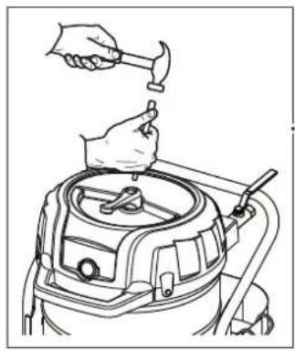
Upstream absolute filter replacement (VHC110 Z1 - VHC120 Z1)
Figure 13
■ Release the closing band (2).
■ Remove the deck (3) overturn it, and lay it on a suitable surface, to avoid any damage.
■ Unscrew the ring nut (6).
■ Remove the disc (7), the iron-rubber washer (8) and the absolute filter (9).
■ Place absolute filter (9) in a plastic bag, close the bag hermetically and dispose of the filter in accordance with the laws in force.
- Insert a new absolute filter (9) with the same filtering characteristics as the removed one.
■ Install the iron-rubber washer (8) and the disc (7), then tighten the ring nut (6).
■ Reinstall the deck (3) and close the closing band (2).
■ Release the stop (1), unscrew the filter shaker knob (2).
■ Release the closing band (3).
■ Lift the cap (4).
■ Unscrew the ring nut (5), and remove the disc (6).
■ Remove old absolute filter (7) and put it in a plastic bag, close the plastic bag hermetically and dispose of it in accordance with the laws in force.
■ Assemble new absolute filter (7), taking care not to damage it. Assemble the components in the reverse order of disassembly.
Installation, cleaning and replacement of the separator (optional)
Figure 14
[ NOTE ]
Instructions describing how to fit the optional kits and the relative operation and maintenance manuals are supplied together with the optional kits.
[ NOTE ]
If there is only a dust deposit on the separator (4) allow the dust to drop through the central hole.
The separator (4) should first be disassembled in order to be perfectly cleaned:
■ Release the closing hooks (1) of the cover (2) and remove the cover.
■ Remove the filter.
■ Unscrew the two screws (3) and remove it from the container.
■ Replace the part if it is excessively worn.
■ Reinstall the separator (4).
■ Lock it and fix it by means of the two screws (3).
■ Fit the filter back in place, close the cover (2) and lock it by means of the two the closing hooks (1).
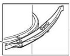
Tightness inspection
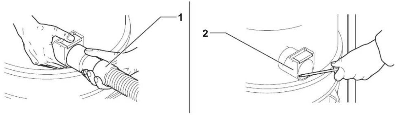
Hoses check
Figure 15
Make sure that connecting hoses (1) are in a good condition and correctly fixed.
If the hoses are damaged, broken or badly connected to the unions, they must be replaced.
When sticky materials are treated, check for possible clogging along the hose, in the inlet and on the baffle plate inside the filtering chamber.
To clean, scrape the inlet (2) from the outside to remove deposits.
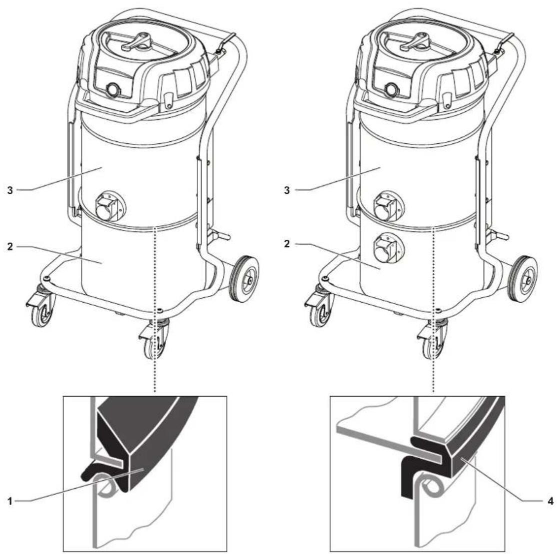
Filtering chamber gasket check for machines equipped with dust container
Figure 16
If the gasket (1) between the container and the filtering chamber (3) fails to guarantee sealing:
■ Loosen the four screws (2) that lock the filtering chamber (3) against the vacuum cleaner structure.
■ Allow the filtering chamber (3) to lower down and tighten the screws (2) once it has reached the sealing position.
If an optimal seal is not yet obtained or if there are tears, cracks, etc., the gasket must be replaced.
Recommended spare parts
The following is a list of spare parts that should be kept ready at hand in order to speed up maintenance operations.
Refer to the manufacturer's spare parts catalogue when ordering spare parts.
| Name | Model | ||
| VHC110VHC120 | VHC110 Z1VHC120 Z1 | ||
 | Star fi Iter kit 4081701390 4081701208 | ||
| Star fi Iter kit (FM) 4081701393 4081701218 | |||
| Star fi Iter kit (FP) 4081701423 4081701417 | |||
| Star fi Iter kit (FN) 4081701392 - | |||
 | Filter ring gasket Z8 17025 | ||
 | Filter chamber gasket 4081100183 | ||
 | Filter clamp 4084001291 | ||
 | Upstream absolute fi Iter 4081701384 | ||
 | Paper Bag (DS - 5 pcs) 81584000 | ||
 | Longopac 4084000956 4084001470 | ||
 | Plastic Bag (PBS) Z8 40099 | Z01769505 | |
 | Safe Bag (SBS) | 4084001468 | |
| Safe Bag (SOBS - 5 pcs) | 4089101052 | ||
Troubleshooting
| Problem Cause Remedy | ||
| The machine is unable to collect the material | Clogged primary filter | Use the filter shaker (models with manual filter shaker). Replace it if this is not sufficient. |
| Clogged vacuum hose | Check the vacuum hose and clean it. | |
| Insufficient airflow | Increase air supply pressure. Check the pressure supplied by the pneumatic network is sufficient. | |
| The machine produces a more acute noise The liquid mechanical stop has activated Emptying of the liquid container. | ||
| Dust leaks from the machine | The filter is torn Replace it with another of identical type. | |
| Inadequate filter | Replace it with another of a suitable category and check. | |
| Electrostatic current on the machine Missing or inefficient grounding | Check all ground connections. In particular on the vacuum inlet fitting; replace the hose with an antistatic hose. | |
GB
Page left intentionally blank
text_image
No.16 Air purifier No.16 Air purifier (PAN) No.16 Air purifier (PAN) Type: No.16 Air purifier 1 2 3 4 5 6 7 8 9 Nillisk © No.16 Air purifier © No.16 Air purifier (PAN) © No.16 Air purifier (PAN)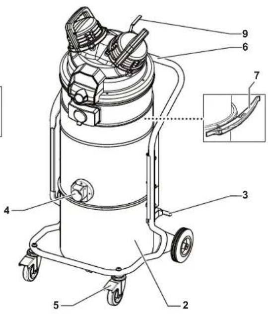
text_image
Technical diagram of a vacuum cleaner with numbered parts and an inset close-up view highlighting internal structure.2
text_image
1 Exx3
text_image
3 A B C4
text_image
A B C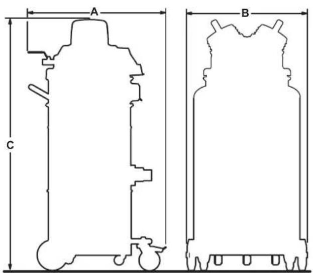
text_image
A B C5
text_image
Technical diagram of a mechanical device with numbered components, showing front and side views with labeled parts 1, 2, and 3.6
natural_image
Line drawing of hands operating a cable or hose assembly (no text or symbols present)7
text_image
1 (RED) 3 (GREEN) STOP OK 28
natural_image
Line drawing of a hand holding a cylindrical container with four wheels (no text or symbols)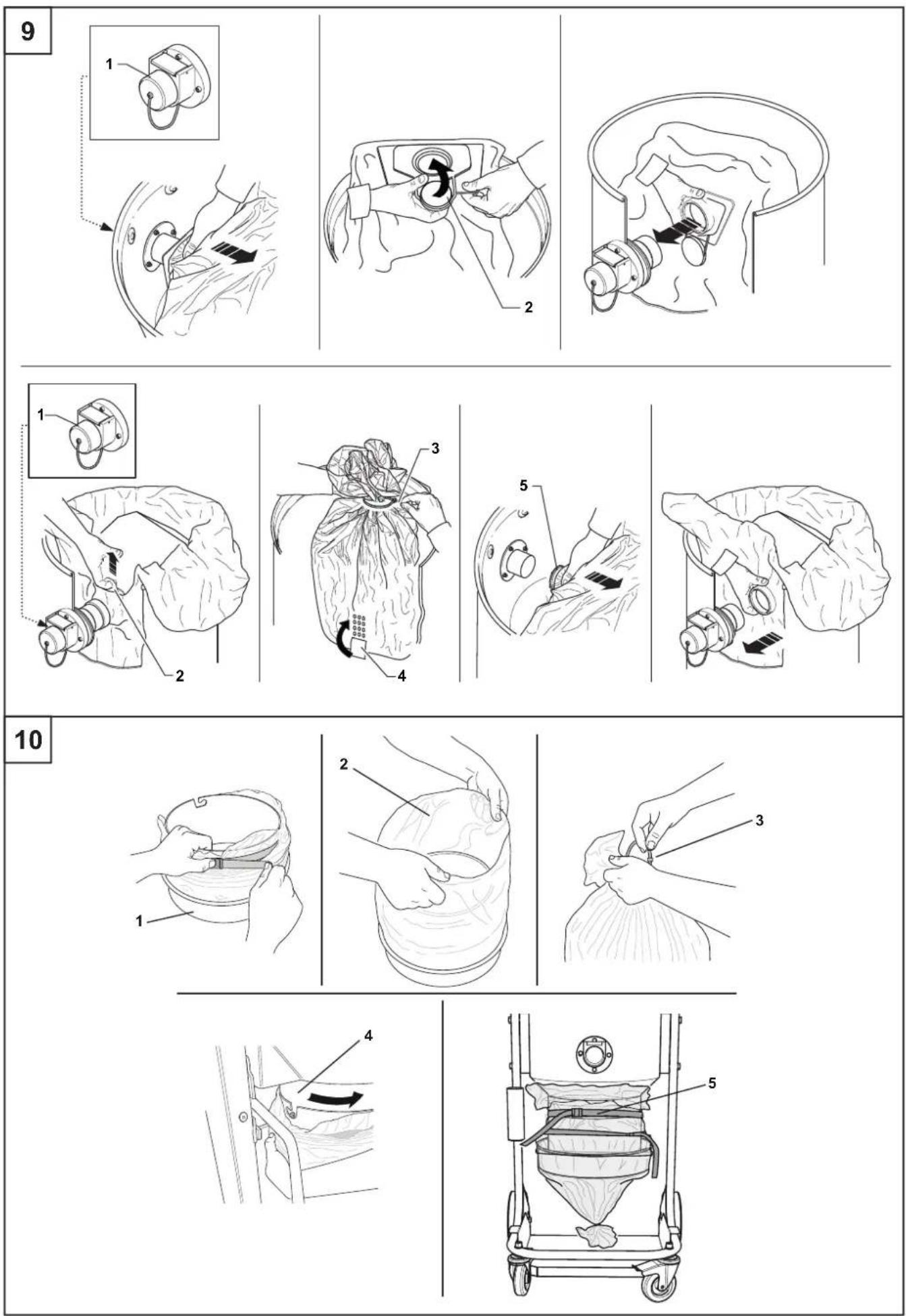
11
text_image
Technical diagram of a cleaning or cleaning machine with numbered components and an inset showing a close-up detail.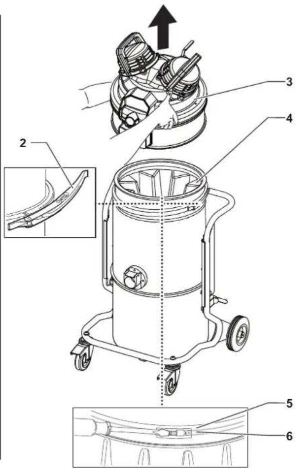
text_image
Technical diagram of a cleaning or repair device with numbered parts and an inset view showing a component detail.12
natural_image
Line drawing of a hand using a hammer to press down a mechanical component (no text or symbols)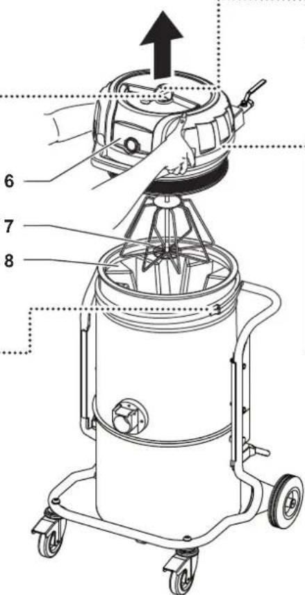
text_image
Technical diagram of a vacuum cleaner with numbered parts and directional arrow indicating operation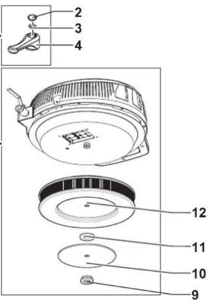
text_image
2 3 4 12 11 10 95
natural_image
Technical line drawing of a curved mechanical component with mounting holes (no text or symbols)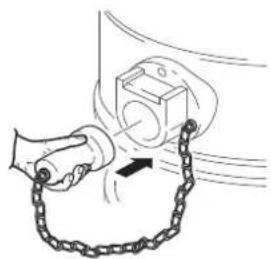
natural_image
Illustration of a hand holding a chain attached to a wall-mounted device (no text or symbols)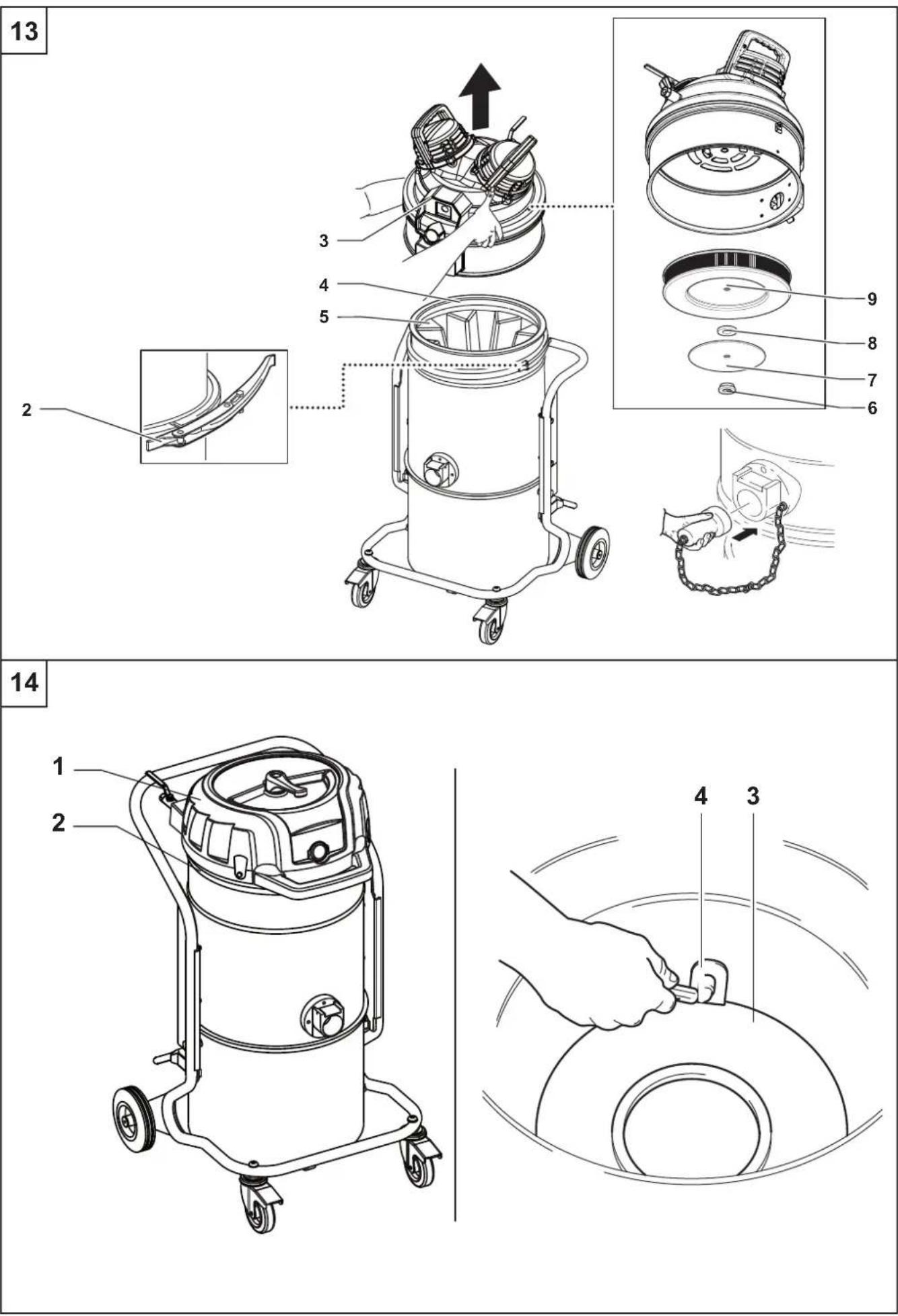
15
text_image
Technical diagram showing two-step installation of a cable or wire, labeled with component number 1 and component 2.16
text_image
Technical diagram of a vacuum cleaner with labeled parts and cross-sectional views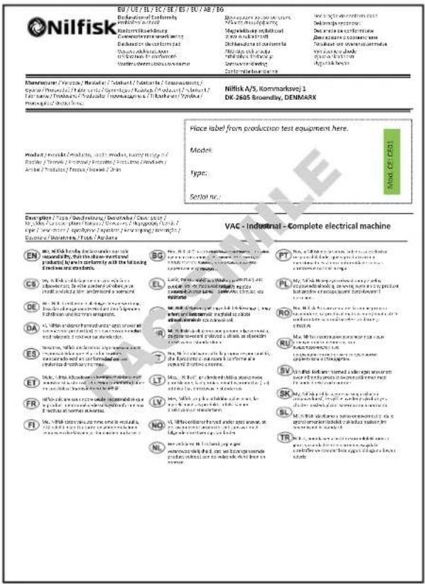
text_image
EU / US / BL / FC / SE / ES / EU / AB / SO Nillfisk Deferencation Conformity Industries used Reformations Deferencation Processing Deferencation decontaminated Deferencation in the process Deferencation in the process Deferencation in the process Deferencation in the process Deferencation in the process Deferencation in the process Deferencation in the process Deferencation in the process Deferencation in the process Deferencation in the process Deferencation in the process Deferencation in the process Deferencation in the process Deferenzen 100% Deferenzen 100% Deferenzen 100% Deferenzen 100% Deferenzen 100% Deferenzen 100% Deferenzen 100% Deferenzen 100% Deferenzen 100% Deferenzen 100% Deferenzen 100% Deferenzen 100% DE EN M. M. M. M. M. M. M. M. M. M. M. M. M. M. M. M. M. M. M. M. M. M. M. M. M. M. M. M. M. M. M. M. M. M. M. M. M. M. M. M. M. M. M. M. M. M. M. M. M. M. M. N. M. M. M. M. M. M. M. M. M. M. M. M. M. M. M. M. M. M. M. M. M. M. M. M. M. M. M. M. M. M. M. M. M. M. M. M. M. M. M. M. M. M. M. M. M. CE M. C. C. C. C. C. C. C. C. C. C. C. C. C. C. C. C. C. C. DA M. D. D. D. D. D. D. D. D. D. D. D. D. D. D. ES M. E. TE M.C. FR M. NI EN M.C. DE M.C. DE DE DE DE DE DE DE DE DE DE DE DE DE DE DE DE DE DE DE DE DE DE DE DE DE DE DE DE DE DE DE DE DE DE DE DE DE DE DE DE DE DE DE DE DE DE DE DE DE DE DE