Polo 2.0 - Heating Enders - Free user manual and instructions
Find the device manual for free Polo 2.0 Enders in PDF.
User questions about Polo 2.0 Enders
0 question about this device. Answer the ones you know or ask your own.
Ask a new question about this device
Download the instructions for your Heating in PDF format for free! Find your manual Polo 2.0 - Enders and take your electronic device back in hand. On this page are published all the documents necessary for the use of your device. Polo 2.0 by Enders.
USER MANUAL Polo 2.0 Enders
natural_image
Exterior view of a stainless steel industrial gas stove with mesh insulation and ventilation slots (no text or symbols visible)
Art.-№ 546023
| CZ | NÁVOD K MONTÁŽI A POUŽITÍ | 2 |
| DE | AUFBAU-/BEDIENUNGSANLEITUNG | 10 |
| FR | MANUEL D'INSTALLATION ET D'UTILISATION | 18 |
| GB | ASSEMBLY AND INSTRUCTION MANUAL | 26 |
| HR | MONTAŽA I UPUTE ZA UPORABU | 34 |
OBSAH STRANA
- CO BUDETE POTŘEBOVAT 2
- DŮLEŽITÉ BEZPEČNOSTNÍ POKYNY 3
- PŘIPOJENÍ PŘÍSTROJE K PLYNOVÉ LÁHVI 4
- UVEDENÍ DO PROVOZU A POUŽÍVÁNÍ 5
- VYPNUTÍ 6
- POKYNY K USCHOVÁVÁNÍ 7
- EKOLOGICKÉ INFORMACE A ZPŮSOB NAKLÁDÁNÍ S ODPADY
-
PORUCHY A JEJICH ODSTRAŇOVÁNÍ 7
-
TECHNICKÉ PARAMETRY 8
- ZÁRUKA A VSIESRU 8
- VÝROBCE 8
- OBSAH DOÁDVKY 9
- JEDNOTLIVÉ MONTÁŽNÍ KROKY 42
1. CO BUDETE POTŘEBOVAT

text_image
Exploded view diagram of a washing machine with numbered parts for identificationINHALT SEITE
text_image
Exploded view diagram of a washing machine with numbered parts for identificationCONTENU PAGE
- CE DONTO UVS VAEZ BESOIN 18
- CONSIGNES IMOPRTANTES DE SÉCURITÉ 19
- RACCORDEMENT DE L'APPAREIL À LA BOUTEILLE DE GAZ 20
- MISE EN MARCHE ET UTILISATION 21
- MISE À'A RLRÊT 22
- CONSIGNES D'ENTREOPSAGE 23
-
INSTRUCTIONS RELATIVES À LA PROTECTION DE L'ENVIRONNEMENT 23 ET À LA MISE AU REBUT
-
PANNES ET USOTILON 23
- CARACTÉRISTIQUES TECHNIQUES 24
- GARANTIE ET DE VICSEER 24
- FABRICANT 24
- COMPOSITION DUO LICS 25
- LES DIFFÉRENTES ÉTAPES DE MONTAGE 42
1. CE DONT VOUS AVEZ BESOIN

text_image
Exploded view diagram of a washing machine with numbered parts for identificationCONTENT PAGE
- WHAT OYU NEED 26
- IMPORTANT SAFEYT INOFRMATION 27
- CONNECTING THE DEVICE TO THE GAS CANISTER 28
- START UP AND USE 29
- TURNING OFF 30
- STORAGE TIPS 31
- ENVIRONMENTAL NOTES AND DISPOSAL MEASURES 31
-
MALFUNCTIONS AND SOLUTIONS 31
-
TECHNICAL DEATILS 32
- WARRANTY AND VSIECRE 32
- MANUFACTURER 32
- INCLUDED IN DELIYVER 33
- THE INDIVIDUAL CONSTRUCTION STEPS 42
1. WHAT YOU NEED

Please store this instruction manual in a safe place for future use. Please read the instruction manual carefully before using the patio heater. Please pay particular attention to the safety instructions. The materials and construction methods used in this device have been chosen to ensure against malfunctions when used properly. Please note - there is a separate book of instructions enclosed for the gas pressure regulator!

CAUTION: In order to prevent injury we recommend wearing safety gloves during assembly! During assembly, get help from a second person.


2. IMPORTANT SAFETY INFORMATION

CAUTION: Only use outdoors or in well-ventilated rooms.
(The definitio of a well-ventilated room is that at least 25% of the surrounding area is open. The surrounding area is the sum of all wall surfaces.)
INTENDED USE:
The patio heater may only be used for heating purposes. The device must be installed according to these instructions.
GENERAL SAFETY NOTES:
- Keep children away from the patio heater during assembly (risk of swallowing small parts) and during use (risk of burning) as well as when it is in storage.
The plastic bag from the packaging material can pose a risk of suffocation if it is put over the head. - Keep the liquid gas bottle in a well ventilated area above the ground.
Do not use the patio heater in flats, houses, cellars, office buildings and other similar spaces.
The device must be placed on a solid, level surface. - Keep all liquid gas canisters out of direct sunlight.
The area of use must have a volume of 20 m³ per 1kW of installed nominal thermal load of the patio heater and it must also be well ventilated (roofed terrace, beer tents etc).
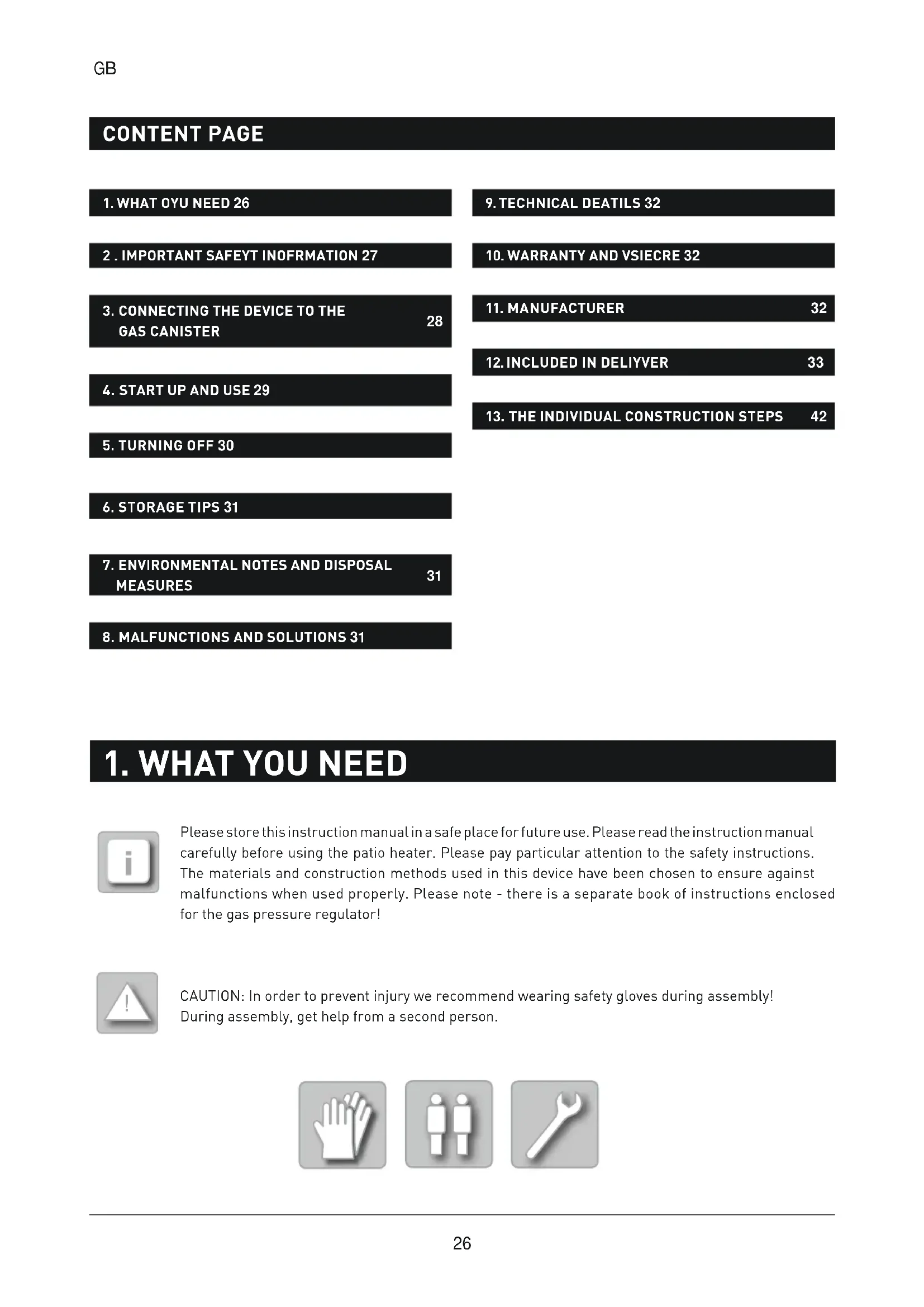
When in use, the device must be placed at a safe distance from combustible materials. The distance between the heat source and the combustible materials must not be less than 2 m in the direction of radiation. Distance in other directions to combustible materials must not be less than 1 m. - Secure the device against falling over or switch it off in high winds.
Check that the sealants on the regulator valve are in place and undamaged before every start up. Do not use any additional sealants.
The patio heater may only be operated using an intermediary pressure regulator with an acceptable exit pressure (see device rating plate and factory settings).
Check the sealant properties of all connections immediately after assembly. Use a foaming agent (e.g. Gas Control Sprayor suds) for this purpose.
The gas hose must not be bent.
■ Never move the device when it is switched on (risk of burning).
Before moving the patio heater to a different location it must be turned off and the gas canister must be removed from the canister holder.
The ventilation holes on the container sleeve of the canister must not be covered. It is possible that gas could leak out and collect in the holder which creates a risk of explosion.
When the device is turned on, the gas canister should always be placed in the designated container sleeve
text_image
Ceiling 1 m Wall 1 mGB
In order to prevent injury from sharp edges we recommend wearing safety gloves during assembly.
■ Only use the gas types and canisters recommended by the manufacturer!
■ Repairs and maintenance of gas-related parts are only to be carried out by authorised specialists.
In case of malfunction, the regulator valve should be closed.
The gas hose should be inspected for damage at least once a month and each time the canister is changed.
The gas hose and pressure regulator should be inspected every five years by an authorised specialist. After 10 years you have to replace the gas hose and pressure regulator by an authorised specialist!
If the gas hose is damaged, it must be replaced by a hose of the same quality and length.
In the event of a gas leakage, the device should not be used. If it is in use, the gas supply must be blocked. Before it is used again, the device must be thoroughly checked and any damaged parts replaced. Any loose connections must be tightened.
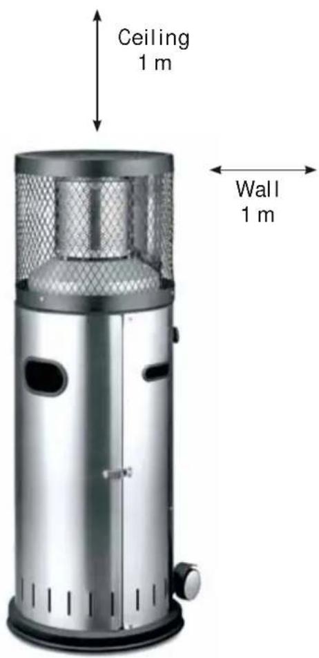
3. CONNECTING THE DEVICE TO THE GAS CANISTER
THE FOLLOWING PARTS ARE NECESSARY TO CONNECT THE APPLIANCE TO THE GAS BOTTLE:
■ commercial propane/butane gas – liquid gas canister
■ fi ed-value approved pressure regulator, 1.5 kg/h, suitable for the gas canister, operating pressure 30 mbar
■ approved 0.4 m hose
■ approved leakage locating spray or foaming agent (e.g. Gas Control Spray or suds).
| A Union nut |
| B Regulator valve |
| C Canister valve |
| D Hose (EN 16436, ∅ 8 mm) |
| E Gas supply |
| Y Gripper clamp |
| Z Gas pressure regulator (EN 16129) |
text_image
Illustration 2. A B C D E Y ZGas bottle: max. 59 cm x ∅ 30 cm
CONNECTING THE GAS CANISTER:

CAUTION: The device must not be used without gas pressure regulator (or one of a similar type). Details regarding country-specifi gas pressure regulators can be found on the type label of the patio heater.
- Check that all sealants are intact before turning on the device.
- Connect the pressure regulator with the regulator valve. Please refer to the separate book of instructions enclosed for the gas pressure regulator.
- Connect the hose to the gas supply of the pressure regulator using the gripper clamp.
- Check that all connection points are leak-proof when the regulator valve is open. For this purpose an approved leakage locating spray or foaming agent (e.g. Gas Control Sprayor suds) is recommended. Apply this to the hose junctions. The sealant properties are ensured if no bubbles appear.

CAUTION: Never check the sealant properties using a naked flam as this could ignite any leaking gas!
CAUTION: The gas canister should only be replaced in a well-ventilated room, away from naked flame (e.g. candles, cigarettes, other devices with naked flames)
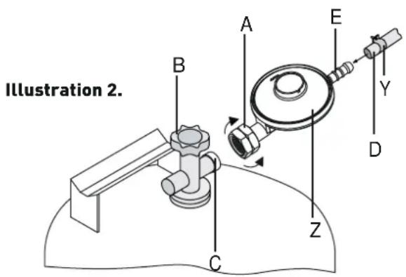
4. START UP AND USE

CAUTION: When starting and stopping the device can be slight explosion at the burner. This is not a failure of the Product and is not cause for alarm. Always keep a safe distance to the burner.
- Open the regulator valve.
- Press the regulator button (F) until the small flam symbol appears and at the same time continuously press the piezo-ignition button (G). After successful ignition, keep the regulator button pressed for another 10 seconds. This brings the burner up to the necessary operating temperature.
- n the rare case that the heater does not ignite after the piezo-ignition button has been pressed 4 or 5 times, repeat the procedure after 2 minutes.

NOTE: It is possible to ignite the device using other primers (matches, fi e sticks) which are ignited through the burner base openings.
5. TURNING OFF
- To switch of the device, close the regulator valve.
text_image
G F6. STORAGE TIPS
Turn the patio heater off and leave it to cool. Close the regulator valve. Remove the pressure regulator with the gas hose from the gas canister. Always check that the sealants are intact.

CAUTION: If you discover or suspect any damage when checking for leaks please contact your operating or fillin station.
CAUTION: Keep the liquid gas bottle in a well ventilated area above the ground..

Store the patio heater in a dry place.
7. ENVIRONMENTAL NOTES AND DISPOSAL MEASURES
To dispose of the patio heater disassemble it.
Separate the parts for recycling including metals, plastic, packaging and the entire burner.
8. MALFUNCTIONS AND SOLUTIONS
PROBLEM:
The patio heater does not ignite.
SOLUTION:
The patio heater contains a tilt prevention device, making possible to encapsulate the gas feed can in a globe during transportation. In order to activate the gas feed, shake the burner head lightly to propel the globe back to its original position and ensure a proper supply of gas.
9. TECHNICAL DETAILS
This device is authorised and approved in DIN EN 14543:2017.
MODEL: POLO 2.0
MANUFACTURER PART NO.: 546023
GAS TYPE: Propan / Butan (G31/G30)
NOMINAL THERMAL STRESS (HS): max. 6 kW
CONSUMPTION: max. 437 g/h
HEIGHT: approx. 115 cm
Countries Category mbar Identification of the injector (mm)
| GB | I3+ | 28-30/37 | ∅ 1,25 |
10. WARRANTY AND SERVICE
We offer a 2 year warranty on the operational function of the device. The warranty is contingent upon proper use of the device and official proof of purchase including the date the device was bought. We reserve the right to make technical and colour-related changes.
The warranty is void after the expiration of the warranty period or immediately if independent changes to the device were performed. Components that have been sealed by the manufacturer or its representative must not manipulations are performed!
If, despite our quality control measures, your product should become damaged please contact Enders directly and do NOT bring it back to the retailer. This enables us to process your inquiry quickly.
SERVIS: www.enders-germany.com
11. MANUFACTURER
Enders Colsman AG
Brauck 1
D-58791 Werdohl
12. INCLUDED IN DELIVERY

Remove the protective foil from all parts fi st! Initially, only fi the screws loosely and then tighten them following complete assembly.
text_image
Exploded view diagram of a washing machine with numbered parts for identificationSADRŽAJ STR.
- ŠTO VAM JE POTREBNO 34
- VAŽNE NAPOMENE U VEZI SIGURNOSTI 35
- PRIKLJUČIVANJE UREĐAJA NA PLINSKU BOCU 36
- STAVLJANJE U POGON I UPOTREBA 37
- ISKLJUČIVANJE 38
- UPUTE ZA ČUVANJE UREĐAJA 39
-
UPOZORENJA VEZANA UZ OKOLIŠ I MJERE ZBRINJAVANJA 39
-
KVAROVI I POMOĆ 39
9.TEHNIČKI PODACI 40 - JAMSTVO/SERVIS 40
- PROIZVOĐAČ 40
- OPSEG ISPORUKE 41
- KORACI SASTAVLJANJA 42
1. ŠTO VAM JE POTREBNO

Spremite ove upute za slučaj da Vam zatrebaju u budućnosti.
text_image
Exploded view diagram of a washing machine with numbered parts for identification13. JEDNOTLIVÉ MONTÁŽNÍ KROKY/AUFBAUSCHRITTE/ LES DIFFÉRENTES ÉTAPES DU MONTAGE/CONSTRUCTION STEPS/KORACI SASTAVLJANJA
text_image
4 1 8 1 9 1
text_image
20 Ø 5,3 2 23 M5 2 26 M5 x 12 2
text_image
Technical diagram of a mechanical assembly with numbered components for identification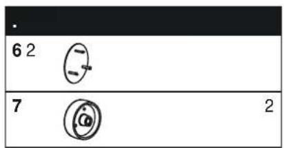
text_image
6 2 7 2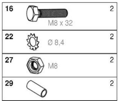
text_image
16 M8 x 32 2 22 Ø 8,4 27 M8 2 29 2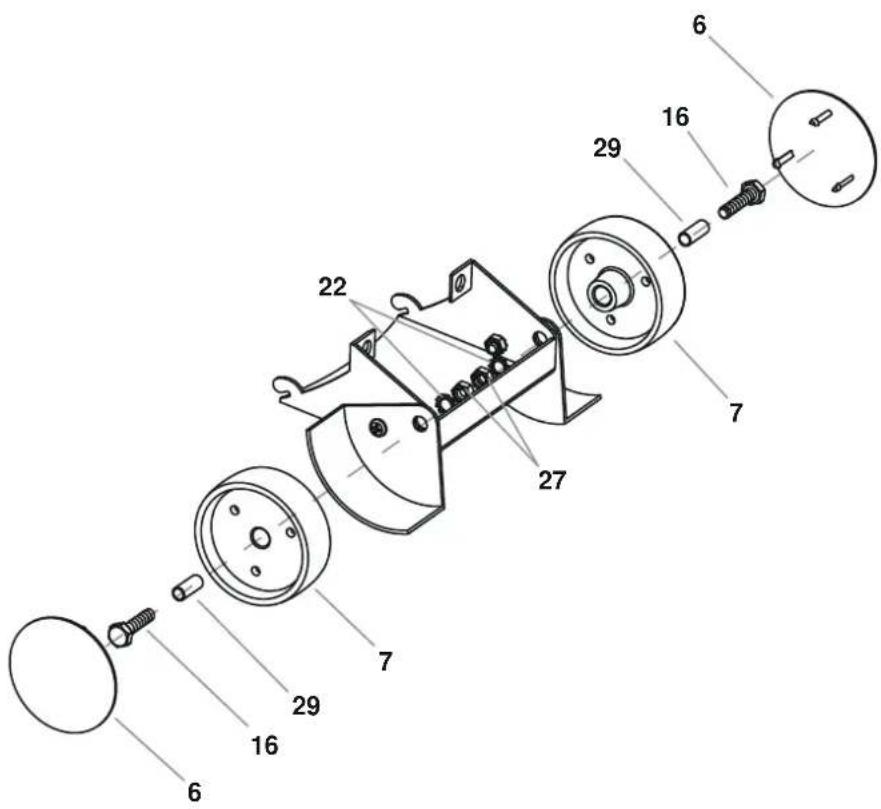
text_image
Exploded view diagram of a mechanical assembly with numbered parts for identification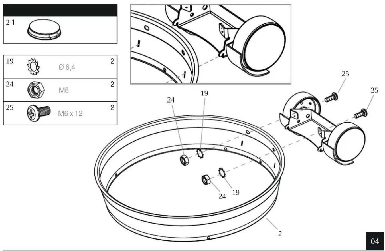
04
text_image
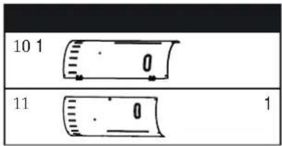
10 1 11 1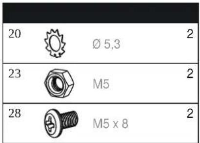
text_image
20 Ø 5,3 2 23 M5 2 28 M5 x 8 2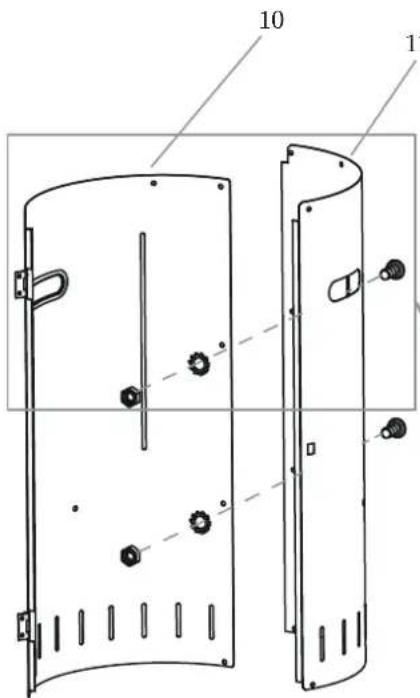
text_image
Technical diagram of a door panel with labeled parts and bolted features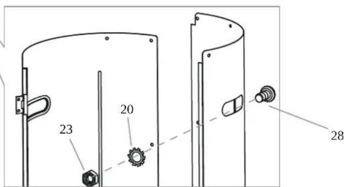
text_image
23 20 28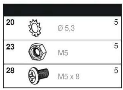
text_image
20 Ø 5,3 5 23 M5 5 28 M5 x 8 5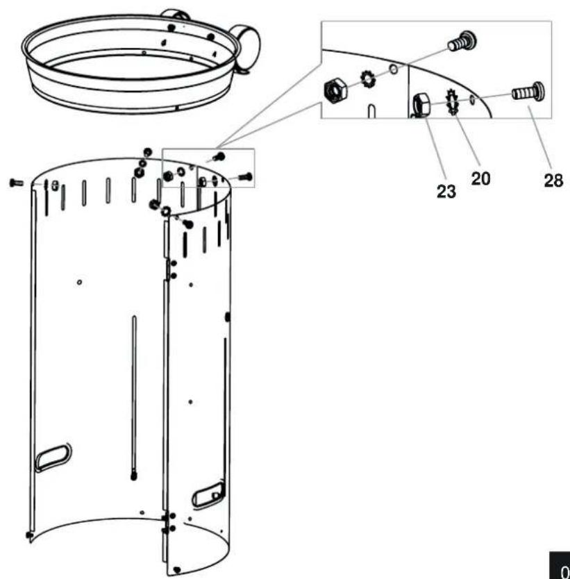
text_image
Technical diagram of a cylindrical device with labeled parts and exploded view, showing internal components and assembly details.06
text_image
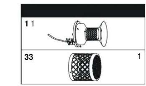
1 1 33 1
text_image
-18 33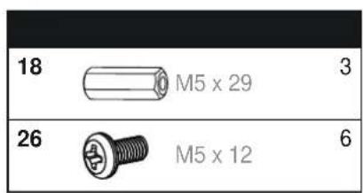
text_image
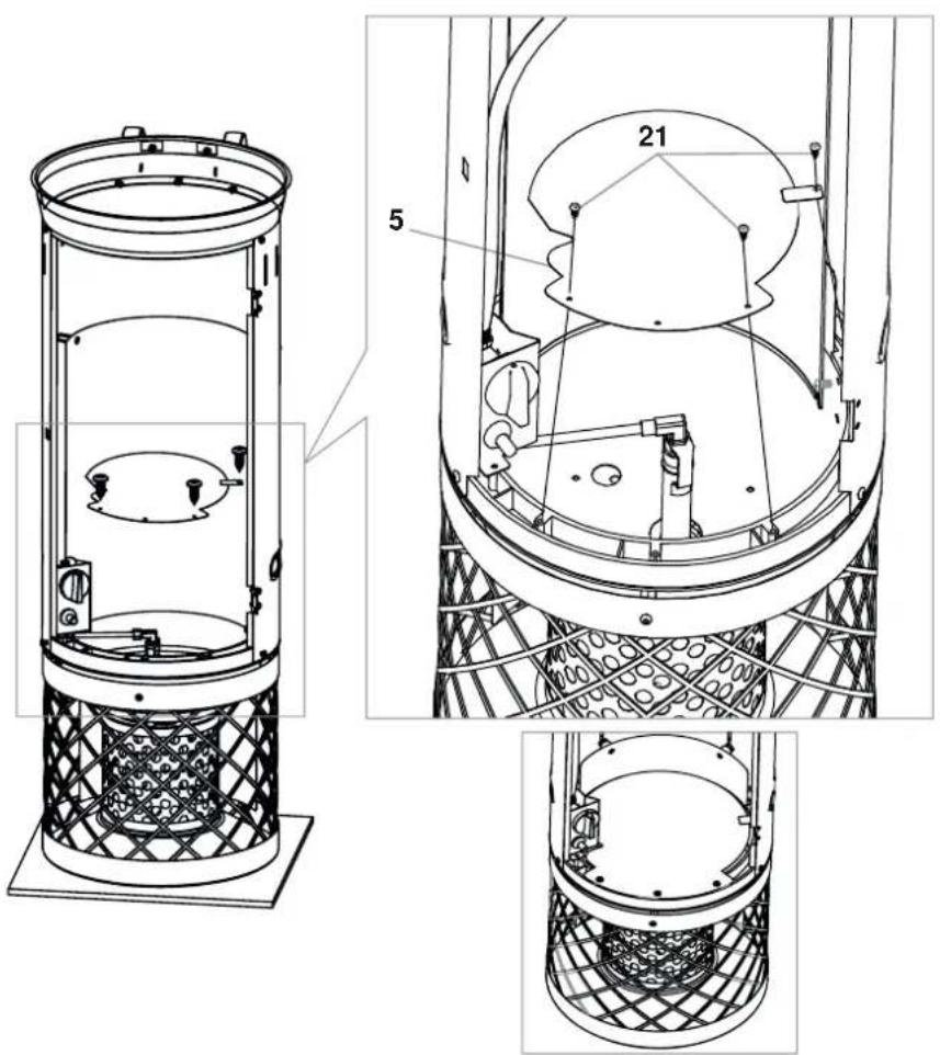
18 M5 x 29 3 26 M5 x 12 6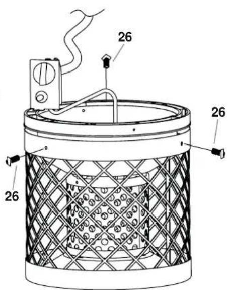
text_image
26 26 26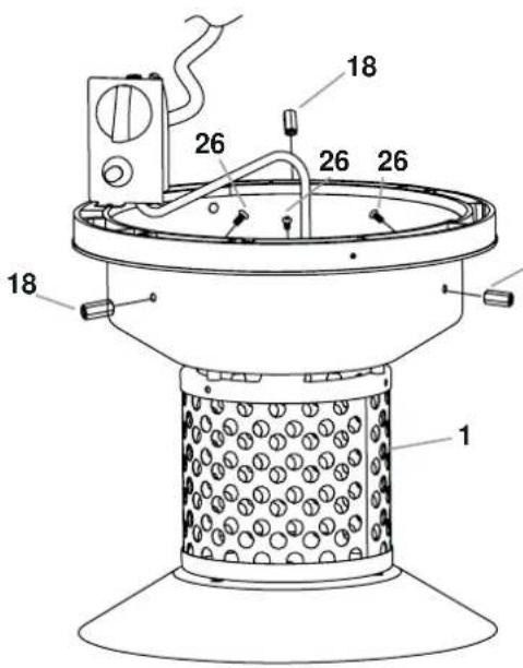
text_image
1 26 18 26 26 18 1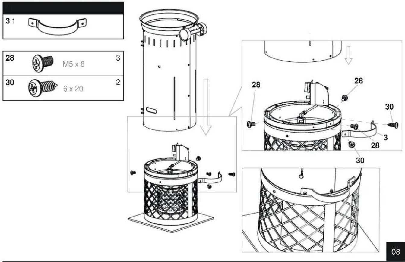
text_image
3 1 28 M5 x 8 3 30 6 x 20 2 28 28 30 3 28 30 08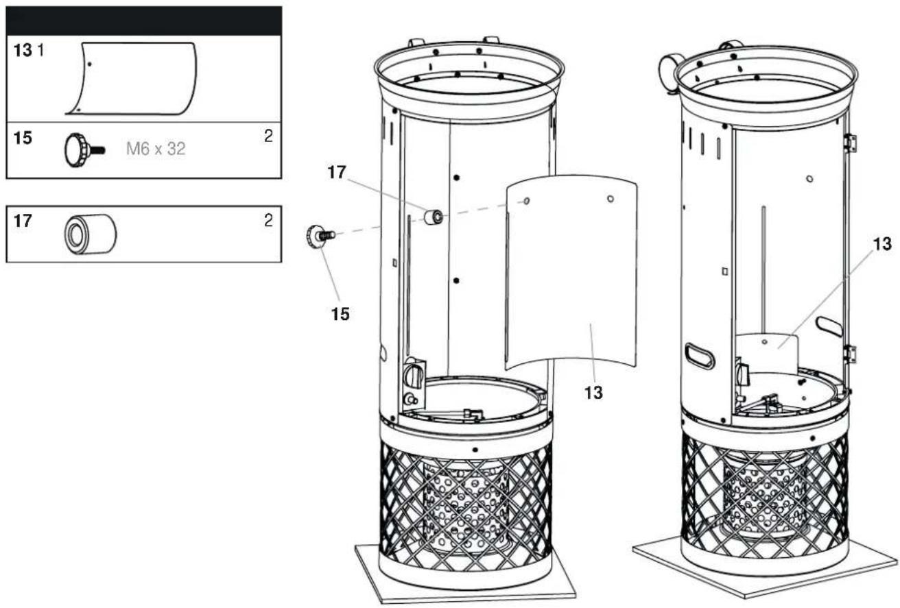
text_image
13 1 15 M6 x 32 2 17 2 17 15 13 13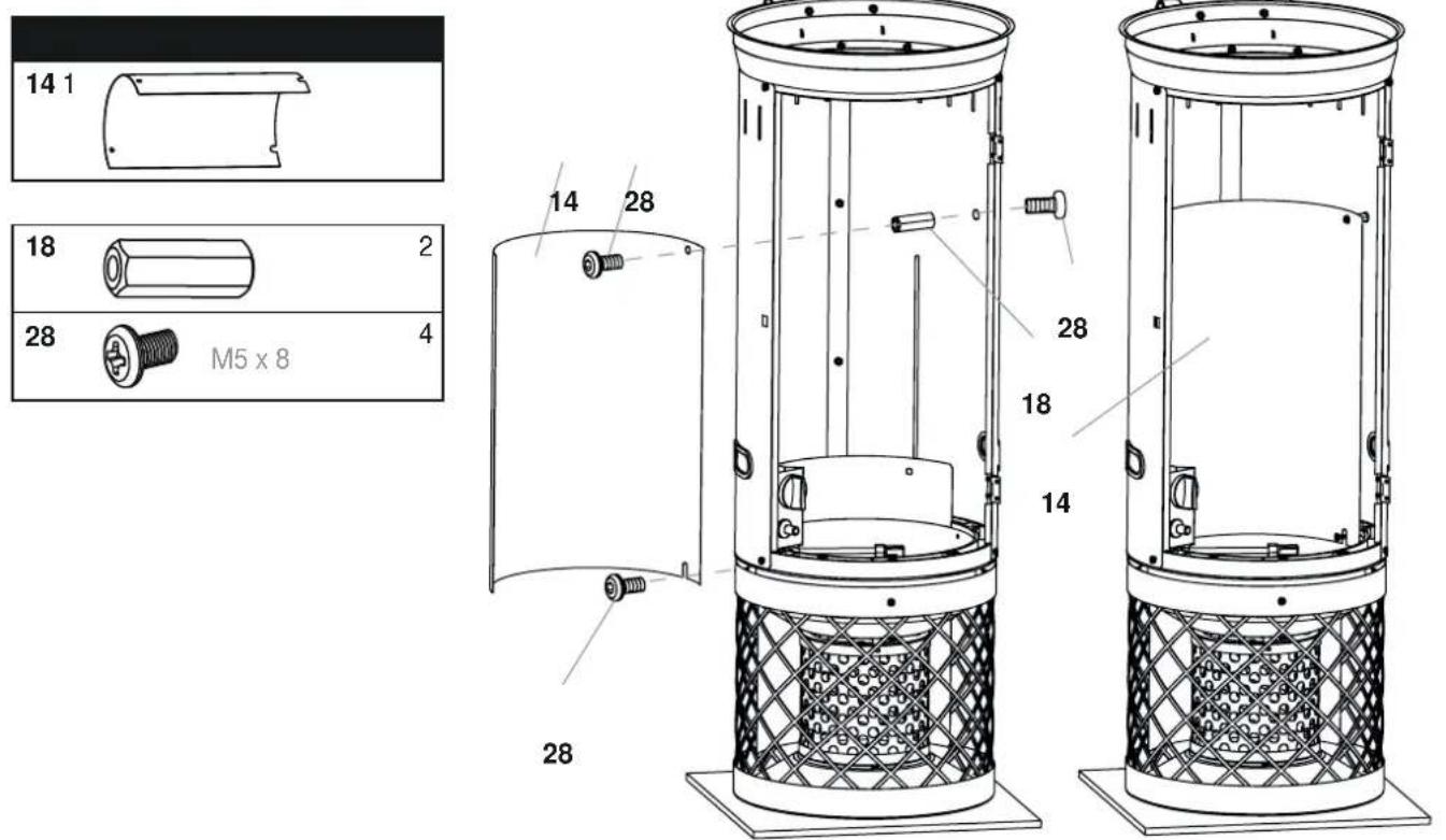
natural_image
Simple line drawing of a helmet outline with no text or symbols
text_image
Technical diagram of a cylindrical device with labeled components and cross-sectional views12 1
23 4
28 4
28
28 23
12
Enders®
Enders Colsman AG
Brauck 1
D-58791 Werdohl, Germany
Tel. 02392 978230