
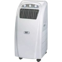
MKA 3000 M - Air conditioner EINHELL - Free user manual and instructions
Find the device manual for free MKA 3000 M EINHELL in PDF.
| Product Type | Monobloc Mobile Air Conditioner |
| Brand | Einhell |
| Model | MKA 3000 M |
| Dimensions (L x D x H) | 40 x 37.7 x 75 cm |
| Net weight | 29 kg |
| Power supply | 230 V ~ 50 Hz |
| Power consumption | 790 W (3.9 A) |
| Cooling capacity | 10 000 BTU/h (2930 W) |
| Maximum air flow | 470 m³/h |
| Dehumidification capacity | 26.4 L/day |
| Fan speeds | 2 (Low / High) |
| Timer | 1 to 8 hours |
| Thermostat range | 18 °C to 32 °C |
| Refrigerant quantity | 470 g |
| Recommended area | up to 85 m³ |
| Filter | Washable air filter (monthly cleaning) |
| Included accessories | Exhaust air hose, wall pass-through ring, condensation water tank, insulation foam |
| Functions | Cooling, fan only, dehumidification |
| Safety | Compressor overheating protection |
| Maintenance | Clean filter and housing with a soft cloth |
| Storage | Empty water tank, clean and store in original packaging |
| Warranty | 2 years |
Frequently Asked Questions - MKA 3000 M EINHELL
User questions about MKA 3000 M EINHELL
0 question about this device. Answer the ones you know or ask your own.
Ask a new question about this device
Download the instructions for your Air conditioner in PDF format for free! Find your manual MKA 3000 M - EINHELL and take your electronic device back in hand. On this page are published all the documents necessary for the use of your device. MKA 3000 M by EINHELL.
USER MANUAL MKA 3000 M EINHELL
natural_image
Diagram of a grid-patterned object with curved arrows indicating rotation or movement (no text or symbols)natural_image
Technical line drawing of a mechanical assembly with labeled components (no text or symbols)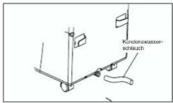
Instandhaltung
Description of device
10
GB
* Please read the Operating Instructions thoroughly before using the device for the first time and then keep them in a safe place.
In purchasing this portable air conditioner you have chosen a high quality product. The device is of a highly professional design and will offer you maximum comfort for many years, as long as you use it in accordance with the Operating Instructions. You should therefore read the instructions thoroughly and keep them in a safe place for future reference.
Before using
- Always place the portable device on a firm footing.
- Connect the device to the correct socket outlet.
- Connect the exhaust air hose to the air conditioner.
Technical data
MKA 2000 M
| Quantity of coolant 440 g | |
| Cooling capacity 6000 BTU/h | |
| 1510 Kcal/h | |
| 1758 Watt | |
Voltage 230 V \~ 50 Hz
| Power rating/current 530 W/2.38 A |
| Max. air throughput 440 cbm/h |
| Room size 55 m |
| Dehumidifying capacity 21.6 l/day |
| Fan speed 2 |
| Timer 1-8 hours |
| Thermostat 18-32°C |
| Dimensions (WxDxH) 40 x 37.7 x 75 cm |
| Net weight 27 kg |
MKA 3501 E
| Quantity of coolant 480 g | |
| Cooling capacity 12000 BTU/h | |
| 3024 Kcal/h | |
| 3529 Watt | |
Voltage 230 V \~ 50 Hz
| Power rating/current 850 W/4.2 A |
| Max. air throughput 520 cbm/h |
| Room size 110 m |
| Dehumidifying capacity 31.2 l/day |
| Fan speed 2 |
| Timer 1 - 12 hours |
| Thermostat 18 – 32°C |
| Dimensions (WxDxH) 40 x 37.7 x 75 cm |
| Net weight 31 kg |
Important note: Consumption values were
measured at a room temperature of 27°C humidity of 60%.
Important safety instructions
Prevention of accidents
- Check that the electrical connection is correct.
- Check that the device is installed correctly in accordance with the Operating Instructions.
- Keep all children and any persons under the influence of medication or alcohol well away from the device.
● Never use the device in the vicinity of bath tubs, showers or wash basins.
● Never place any objects on the air vents.
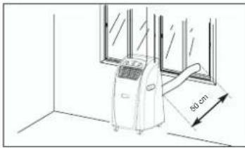
● Never place closer than 50 cm to the wall.
- Close the window curtains whenever there is strong sunlight or adjust the venetian blinds accordingly.
- Keep the air filter clean. Under normal conditions the filter requires cleaning once a month. Since the air filter also catches very small particles of dust, it may be necessary to clean it more frequently. Never operate the device without the air filter.
- When you start the device, set the fan to a high speed and the thermostat to the highest cooling setting. Reduce to LOW COOLING later and set the THERMOSTAT to the desired temperature.
Additional Instructions:
● Never use an extension cable or an auxiliary plug to which another device is connected in addition to the air conditioner.
- In the cooling function the warm exhaust air must be transferred outside by the hose. An opening in the wall or window is therefore essential for the exhaust air set included in delivery.
● Always pull out the mains plug after use or before starting any maintenance work.
- Ensure that the device never comes into contact with any chemicals.
- All work of maintenance or repair must be performed by an electrician or cooling system specialist only.
GB
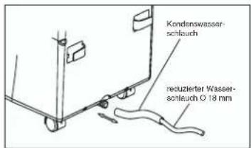
Accessories
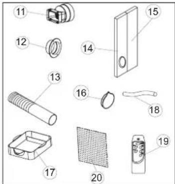
11 Exhaust air connection fittings
12 Bushing ring
13 Exhaust air hose
14 Foam material (Used for exhaust air outlet through the window.)
15 Foam material (Used for exhaust air outlet through the open window and placed in the open section of the window. As far as possible, no additional warm air should come into the room from outside.)
16 Cap for the hole in the window/wall
17 Collection tank for the condensation water
18 Drainage water hose
19 Remote control (MKA 3501 E)
20 Activated carbon filter
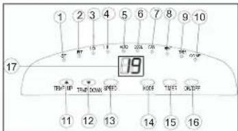
Description of the control elements
MKA 2000 M / MKA 3000 M
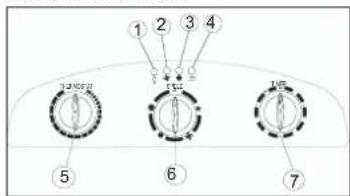
- Voltage display
- Fan status indicator
- Cooling status indicator
- Condensation water tank "Full" indicator
- Thermostat (+18°C to +32°C)
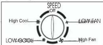
- Cooling and fan switch
Low Fan; High Fan; Low Cool; High Cool and Off function - Timer controller
1 - 8 hours can be set. The timer controller can be used to switch the system on/off.
Off = System switched off
Low Fan = Fan runs at slow speed
High Fan = Fan runs at high speed
Low Cool = Low cooling
High Cool = High cooling
Using the device for the first time
MAINS PLUG Plug the mains plug into the mains socket outlet.
START Set the timer controller to ON. The
device starts up automatically. Whenever the temperature exceeds 23°C the cooling function starts automatically. Whenever the temperature is below 23°C, only the fan will run. The device keeps running until it is switched off.
SWITCHING OFF Turn the timer controller to "OFF"
and the device switches off immediately.
Setting the temperature
Set the thermostat according to your requirements.
Turning in a clockwise direction reduces the set-point temperature.
Setting the timer
Set the timer according to your requirements (1 - 8)
hours). The device switches off automatically once the set time has elapsed.
Description of the control elements
MKA 3501 E
- LED "Set temperature"
- LED "Room temperature"
- LED "Fan: Slow"
- LED "Fan: Fast"
- LED "Automatic mode set"
- LED "Cool mode set"
- LED "Fan mode set"
- Not assigned
- LED "Timer actuated"
- LED "Compressor on"
- "Warmer" selector
- "Cooler" selector
- "Fan speed" selector
- "Mode" selector
- "Timer" switch
- On/off switch
- LCD indicator panel
Switching the device on and off
Press the On/Off switch. The device starts up automatically. If the ambient temperature:
- is higher than 23°C the device will run in cooling mode;
- if it is between 20°C and 23°C the device will run in fan mode.
The status of the device, or mode in which it is running, will be shown by the corresponding LEDs (see indicator panel).
Note: The "Compressor on" LED (COMP) only lights up when the compressor is actually running. The LCD indicator panel shows the current room temperature.
To switch the device off, press the On/Off switch
again.
Selecting the mode
Press the "Mode" selector (MODE) in the sequence "Automatic", "Cool", "Fan". The LED for the selected mode lights up (see indicator panel).
Setting the set-point temperature
Press the "Warmer" selector (TEMP.UP) or "Cooler"
GB
(TEMP.DOWN) to set your desired set-point temperature. If you press the "Warmer" or "Cooler" selector, the LCD Indicator panel will show your desired set-point temperature. Otherwise the LCD indicator panel always shows the current room temperature. The device's cooling mode is set to 24°C.
Selecting the fan speed
Press the "Fan speed" selector (SPEED) to set the desired fan speed.
The LED for the mode lights up (see indicator panel). If the device is in "Automatic mode" (AUTO) the fan speed will be selected automatically by the device in dependency on the room temperature. The corresponding LED lights up. The "Fan speed" (SPEED) is deactivated.
Setting the timer
Press the switch for the "Timer" (TIMER) to set the desired operating time (1 - 12 h). The "Timer" (TIMER) LED lights up. If the timer is set, the device starts automatically. If you press the "Timer" switch, the time you have set will be shown in the LCD indicator panel. If the timer has not been switched on, the device will run continuously.
If you press the switch for the "Timer" (TIMER) without any of the other modes being switched on you can set the time that the device is to start up. If, for example, the timer shows "2", this means that the device will start up automatically in 2 hours time. All modes and functions can be set using the supplied remote control.
The remote control requires two MICRO (AAA) batteries.
In order to protect the compressor, it only starts up 3 minutes after the device starts up. The same applies when the device is switched off.
The cooling system switches itself off whenever the room temperature is below the value set on the thermostat. The air circulation/ventilation fan continues to run as set. If the room temperature increases again, the cooling system switches on again.
GB
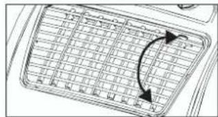
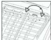
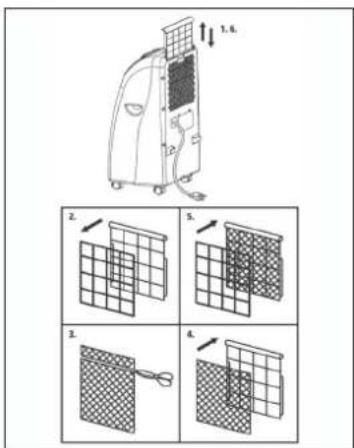
SETTING THE AIR FLOW DIRECTION
- Adjusting the horizontal ventilation grille: The horizontal direction of the air flow is determined by the horizontal ventilation grille. It has to be adjusted by hand.
natural_image
Diagram of a grid layout with directional arrows indicating orientation (no text or symbols)- Adjusting the vertical ventilation grille: The vertical direction of the air flow is determined by the vertical ventilation grille. It has to be adjusted by hand.
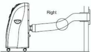
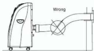
INSTALLING THE EXHAUST AIR HOSE
Use only the supplied exhaust air hose. The length of the exhaust air hose can be varied from between 300 mm to 1500 mm. For the most effective cooling the hose should be as short as possible. Avoid kinks are excessive bends in the hose so that the exhaust air can be transferred out without hindrance. If you ignore this advice, the device as a whole may overheat and shut down. This could result in damage to the device.
Warning!
The length of the exhaust air hose is matched to the technical specifications of the device. Never extend the hose as this could lead to malfunctions or faults on the device.
A) Installing the exhaust air hose through an open window

GB
Use the foam parts and shorten them if required. Guide the exhaust air hose through the opening in the foam to the outside. Secure the window so that the foam is kept firmly in place.
Note: Take appropriate precautions to prevent unauthorized entry through the window.
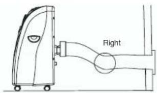
B) Installation of the exhaust air hose through the window pane or the wall
natural_image
Line drawing of an air conditioner unit placed near a window with a 50 cm height dimension label (no text or symbols on the device itself)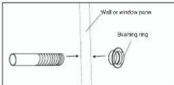
● Cut or drill a hole of approx. 130 mm diameter though the window pane or the wall.
- Insert the bushing ring from the outside to the inside and fasten.
● Feed the exhaust air hose through the bushing ring.
- When the system is not being used, fit the cap on the bushing ring on the outside.
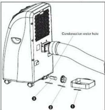
C) Draining off the condensation water with the water tank
ALL OF THE CONDENSATION WATER MUST BE DRAINED OFF BEFORE YOU EVER RELOCATE OR STOP USING THE DEVICE:
Draining off the condensation water with the tank.
Note on MKA 2000 M / MKA 3000 M
When the condensation water tank is full the
"Condensation water tank full" indicator lights up and
the compressor switches off automatically. Only the fan motor continues to run. The cooling function stops.
Note on MKA 3501 E
When the condensation water tank is full the compressor and the fan motor shut down. The
"COMP" LED flashes.
Empty the tank as described below:
- Pull out the mains plug.
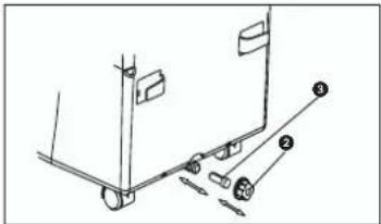
- Slide the tank (1) under the drainage screw (2).
- Unscrew the drainage screw (2).
- Remove the bung (3).
- The condensation water drains out into the drip bowl.
- Once the condensation water has been completely emptied, fit the bung (3) and the drainage screw (2) back on again.
- The device is then ready to be used again.
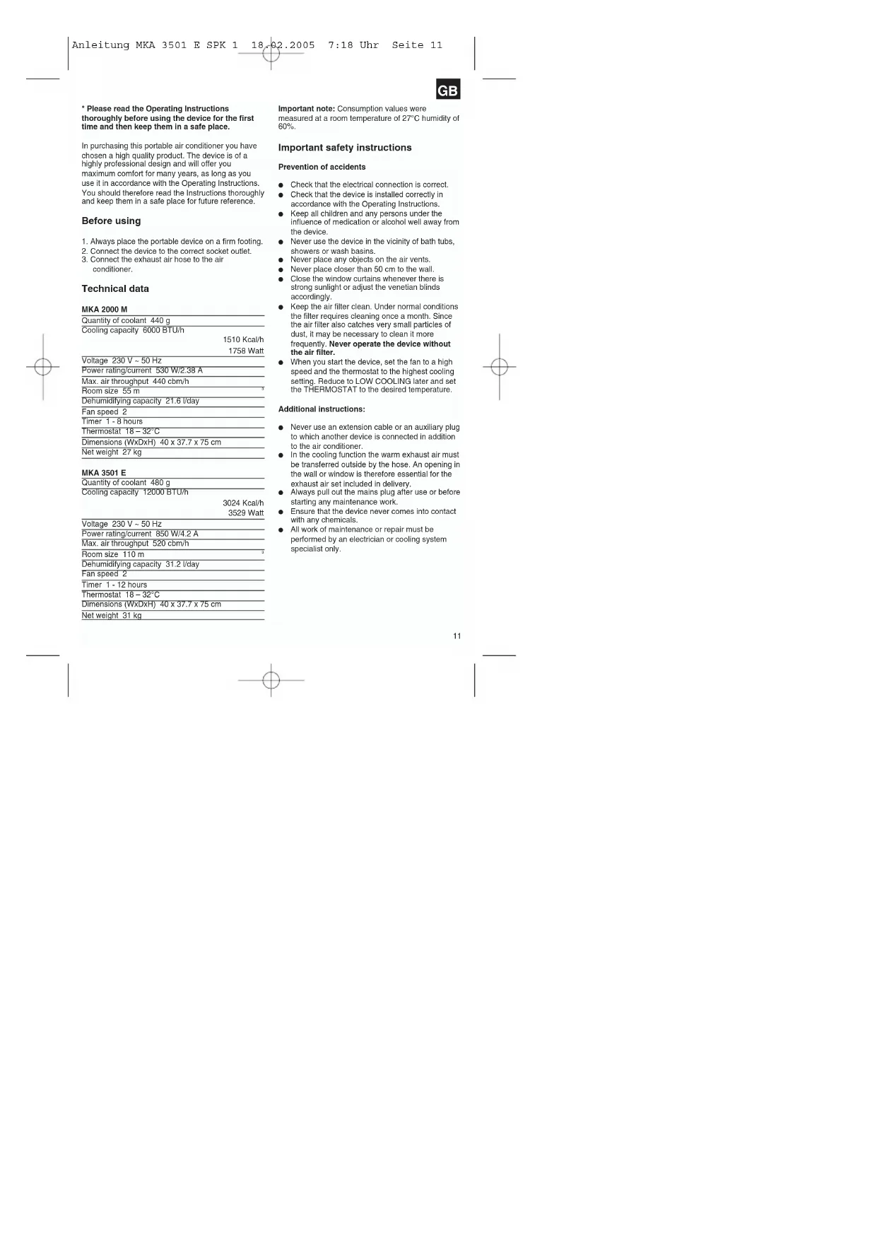
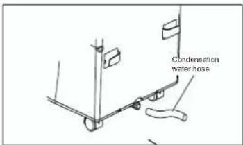
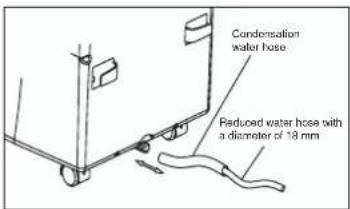
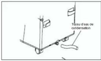
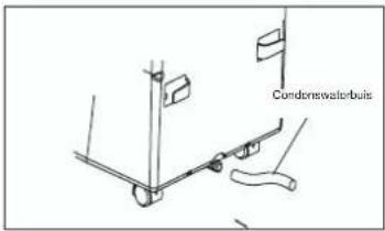
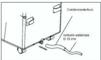
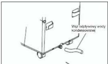
D) Draining off the condensation water with the condensation water hose
- Pull out the mains plug.
- Unscrew the drainage screw (2).
- Remove the bung (3)
- Fit the condensation water hose and secure with the clamp.
- The drainage hose can be extended with a hose with a diameter of 18mm. If you do so, make sure you use a suitable connector.
Note:
The drainage hose must run to the outside with a
GB
slight fall.
MKA 2000 M / MKA 3000 M
The "Condensation water tank full" is defective.
MKA 3501 E
The LED "COMP." Does not flash because the tank cannot become full any more.
Maintenance
- Always pull out the mains plug first to avoid an electric shock or risk of fire.
- Use only gentle cleaner and a soft cloth to clean the filter and the housing. Never use aggressive media, petrol, alcohol or thinner. Only fit the filter back in place when thoroughly dry.
- At the end of the season, please empty the water tank, roll up the power cable, clean the filter and the housing, then fit the filter back in place when dry, and pack the device back in the original box for storage. Never place any heavy objects on the device.
Replacing the carbon filter
- Take out the filter frame
- Remove the filter fastener from the filter frame
- Take the carbon filter out of the bag
- Place the carbon filter in the filter frame
- Fasten the filter with the filter fastener
- Slide in the filter frame
Technical data
MKA 3000 M
| Quantity of coolant 470 g | |
| Cooling capacity 10000 BTU/h | 2520 Kcal/h2930 Watt |
| Voltage 230 V - 50 Hz | |
| Power rating/current | 830 W/3,9 A |
| Max. air throughput 470 cbm/h | |
| Room size 85 m | |
| Dehumidifying capacity 26.4 l/day | |
| Fan speed 2 | |
| Timer 1 - 8 hours | |
| Thermostat 18 - 32°C | |
| Dimensions (WxDxH) 40 x 37.7 x 75 cm | |
| Net weight | 29 kg |
TROUBLESHOOTING
If the device is operated properly you should experience no problems with malfunctions or faults. In the event of any malfunctions or faults, please check the following before you contact your customer services.
| Problem | Possible cause |
| Device does not work | Is the mains plug properly connected?Is there a voltage supply at the mains socket outlet?Is the room temperature below the set-point temperature?Is the condensation water tank full? |
| The device does not provide satisfactory cooling | Is the room exposed to direct sunlight?Are any doors and windows open?Are there a lot of people in the room?Is a device in the room generating a lot of heat? |
| Weak ventilation performance | Is the air hose blocked?Is the filter soiled?Is the air inlet or air outlet blocked? |
| The device is too loud | Has the device been set up on an uneven surface/at an angle? |
| The compressor does not work | Is the condensation water tank full?Is the compressor overheated and the overheating cutout has switched the compressor off? Wait until the compressor cools down. |
Have the device inspected by a specialist firm when you have used it for some time.
F
OFF = installation hors circuit
natural_image
Diagram of a grid-patterned object with an arrow indicating rotation or direction (no text or symbols)natural_image
Line drawing of an air conditioner unit in a room with window and door, showing airflow direction (no text or symbols)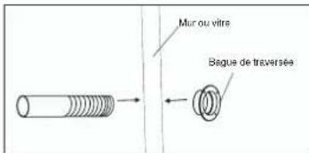
Entretien
natural_image
Line drawing of an air conditioner unit in a room with a 50 cm height dimension label (no text or symbols on the device itself)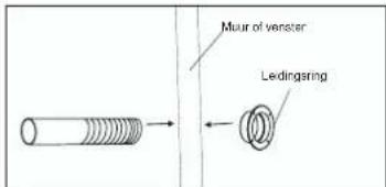
Onderhoud
natural_image
Diagram of a grid-patterned object with curved arrows indicating rotation or direction (no text or symbols)natural_image
Line drawing of an air conditioner unit in a room with window and door (no text or symbols)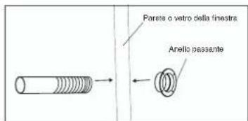
natural_image
Technical line drawing of a mechanical assembly with labeled parts (no text or symbols present)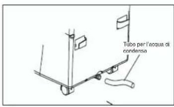
Manutenzione
natural_image
Diagram of a grid-patterned object with directional arrows indicating rotation or movement (no text or symbols)natural_image
Line drawing of an air conditioner unit in a room with a 50 cm height dimension label (no text or symbols on the device itself)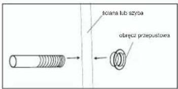
Dbanie o urządzenie
Subject to change without notice
The product described in these instructions comes with a 2-year warranty covering defects. This 2-year warranty period begins with the passing of risk or when the customer receives the product.
For warranty claims to be accepted, the product has to receive the current maintenance and be put to the proper use as described in the operating instructions.
Your statutory rights of warranty are naturally unaffected during these 2 years.
This warranty applies in Germany, or in the respective country of the manufacturer's main regional sales partner, as a supplement to local regulations. Please note the details for contacting the customer service center responsible for your region or the service address listed below.
NL GARANTIE
Eschenstraße 6 · D-94405 Landau/Isar (Germany)
Info-Tel. 0180-5 120 509 • Telefax 0180-5 835 830
@ Recycling alternative to the demand to return electrical devices: As an alternative to returning the electrical device, the owner is obliged to cooperate in ensuring that the device is properly recycled if ownership is relinquished. This can also be done by handing over the used device to a returns center, which will dispose of it in accordance with national commercial and industrial waste management legislation. This does not apply to the accessories and auxiliary equipment without any electrical components which are included with the used device.
natural_image
Simple line drawing of a trash bin with no text or symbols© Nur für EU-Länder
For EU countries only
Never place any electric tools in your household refuse.
To comply with European Directive 2002/96/EC concerning old electric and electronic equipment and its implementation in national laws, old electric tools have to be separated from other waste and disposed of in an environment-friendly fashion, e.g. by taking to a recycling depot.
The reprinting or reproduction by any other means, in whole or in part, of documentation and papers accompanying products is permitted only with the express consent of ISO GmbH.
F

- Instandhaltung
- GB
- Before using
- Technical data
- Important safety instructions
- Prevention of accidents
- Additional Instructions:
- Using the device for the first time
- Description of the control elements
- Switching the device on and off
- Selecting the mode
- Setting the set-point temperature
- Selecting the fan speed
- Setting the timer
- SETTING THE AIR FLOW DIRECTION
- INSTALLING THE EXHAUST AIR HOSE
- Warning!
- C) Draining off the condensation water with the water tank
- D) Draining off the condensation water with the condensation water hose
- MKA 2000 M / MKA 3000 M
- MKA 3501 E
- Maintenance
- Replacing the carbon filter
- TROUBLESHOOTING
- F
- Entretien
- Onderhoud
- Manutenzione
- Dbanie o urządzenie
- NL GARANTIE
Brand : EINHELL
Model : MKA 3000 M
Category : Air conditioner