HD 9/20-4 S ST Classic - Pressure washer Kärcher - Free user manual and instructions
Find the device manual for free HD 9/20-4 S ST Classic Kärcher in PDF.
| Product type | Professional pressure washer |
| Brand | Kärcher |
| Model | HD 9/20-4 S ST Classic |
| Supply voltage | 400 V / 3-phase / 50 Hz |
| Connected load | 7 kW |
| Main fuse | 16 A (slow-blow, curve C) |
| Operating pressure (standard nozzle) | 20 MPa (200 bar) |
| Maximum overpressure | 26 MPa (260 bar) |
| Water flow rate | 15 l/min |
| Max. supply temperature | 60 °C |
| Length | 720 mm |
| Width | 522 mm |
| Height | 418 mm |
| Typical operating weight | 44.8 kg |
| Pump oil type | Motor oil SAE 15W-40 |
| Pump oil volume | 0.65 l |
| Standard nozzle size | 047 |
| Sound pressure level (LpA) | 71 dB(A) |
| Guaranteed sound power level | 88 dB(A) |
| Protection type | IPX5 |
| Main functions | High-pressure cleaning (straight jet), low-pressure cleaning with detergent (via accessory) |
| Possible mounting | On feet (horizontal) or wall-mounted |
| Warranty | According to country conditions, material or manufacturing defects |
Frequently Asked Questions - HD 9/20-4 S ST Classic Kärcher
User questions about HD 9/20-4 S ST Classic Kärcher
0 question about this device. Answer the ones you know or ask your own.
Ask a new question about this device
Download the instructions for your Pressure washer in PDF format for free! Find your manual HD 9/20-4 S ST Classic - Kärcher and take your electronic device back in hand. On this page are published all the documents necessary for the use of your device. HD 9/20-4 S ST Classic by Kärcher.
USER MANUAL HD 9/20-4 S ST Classic Kärcher
natural_image
Exterior view of a KLECHER pressure water heater with attached hoses and fittings (no text or symbols visible)Deutsch 4
English 12
Français 20
Italiano 29
Español 37
Português 46
Nederlands 54
Türkçe 62
Svenska 70
Suomi 78
Norsk 86
Dansk 93
Eesti 101
Latviešu 108
Lietuviškai 117
Polski 125
Magyar 134
Čeština 142
Slovenčina 150
Slovenščina 158
Românește 166
Hrvatski 175
Srpski 183
Ελληνικά 191
Русский 200
Українська 209
Български 218
中文 228
العربيه 235
A
text_image
Exploded view diagram of a Karcher water purifier with numbered parts and component labels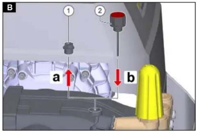
text_image
B 1 2 a b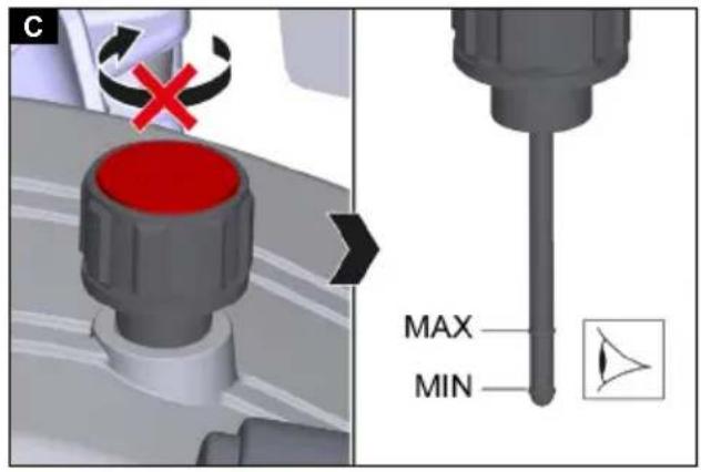
text_image
C MAX MIN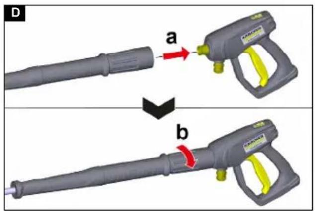
text_image
D a b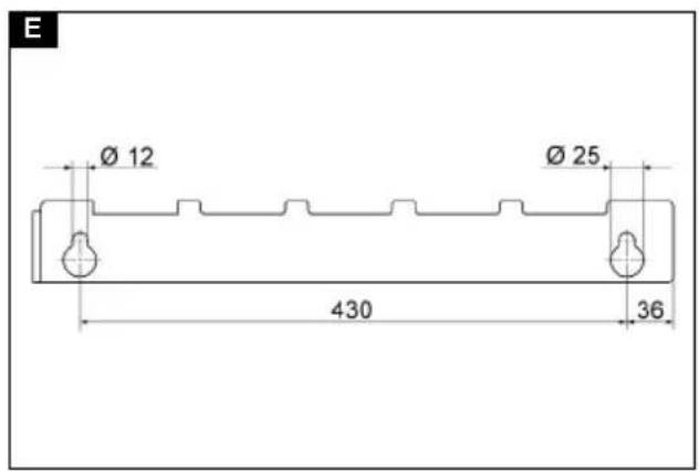
text_image
E Ø 12 Ø 25 430 36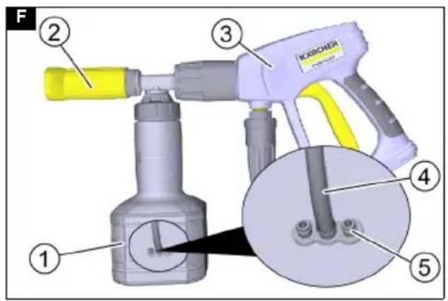
text_image
F ① ② ③ ④ ⑤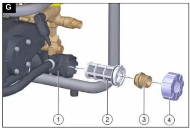
text_image
G ① ② ③ ④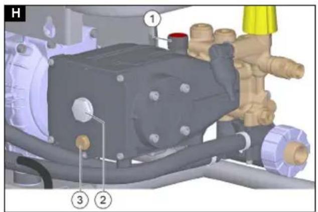
text_image
H ① ③ ②Inhalt
Chairman of the Board of Management
S. Reiser
Manager Regulatory Affairs & Certification
71364 Winnenden (Germany)
Tel.: +49 7195 14-0
Fax: +49 7195 14-2212
Winnenden, 2023/02/01
Contents
General notes.... 12
Intended use.... 12
Environmental protection.... 12
Accessories and spare parts 12
Scope of delivery.... 12
Safety instructions 13
Device description 13
Installation 13
Electrical connection 14
Water connection.... 15
Operation.... 15
Transport 16
Storage.... 16
Care and service 17
Troubleshooting guide.... 17
Warranty 18
Technical data 18
Declaration of Conformity.... 19
General notes


Read these original operating instructions and the enclosed safety instructions before using the device for the first
time. Proceed accordingly.
Keep both books for future reference or for future owners.
Intended use
Use this high-pressure cleaner only for the following types of work:
- Cleaning with the high-pressure jet without detergent (e.g. façades, terraces, garden machines)
- Cleaning with the low-pressure jet and detergent (e.g. machines, vehicles, structures, tools) Optional accessories required, e.g. dosing unit, detergent injector, cup foam lance.
For the most stubborn contamination, we recommend the dirt grinder accessory.
ATTENTION
Risk of damage due to insufficient lubrication!
If the device stands or hangs at an angle, the high-pressure pump can be damaged by insufficient lubrication.
Only operate the device when it is standing horizontally with the feet on level ground or in the same orientation after wall mounting.
Do not operate the device with servo control accessories.
Inlet water limit values
ATTENTION
Risk of damage due to unsuitable inlet water!
Supply water whose properties and content materials exceed the permissible limit values causes premature wear or deposits in the device.
Only use clean inlet water (also recycled water) whose properties and content materials are within the permissible limits.
The following limit values apply to the inlet water:
• pH value: 6.5-9.5
- Electrical conductivity: Conductivity of fresh water + 1200 μS/cm, maximum conductivity 2000 μS/cm
- Settleable particles (sample volume 1 l, settling time 30 minutes): < 0.5 mg/l
- Filterable particles: < 50 mg/l, no abrasive substances
• Hydrocarbons: < 20 mg/l
• Chloride: < 300 mg/l
• Sulphate: < 240 mg/l
• Calcium: < 200 mg/l
- Total hardness: < 28 °dH, < 50° TH, < 500 ppm (mg CaCO₃/l)
- Iron: < 0.5 mg/l
• Manganese: < 0.05 mg/l
• Copper: < 2 mg/l
• Active chloride: < 0.3 mg/l
• Free of unpleasant odours
Environmental protection

The packing materials can be recycled. Please dispose of packaging in accordance with the environmental regulations.

Electrical and electronic devices contain valuable, recyclable materials and often components such as batteries, rechargeable batteries or oil, which - if handled or disposed of incorrectly - can pose a potential danger to human health and the environment. However, these components are required for the correct operation of the device. Devices marked by this symbol are not allowed to be disposed of together with the household rubbish.
Notes on the content materials (REACH)
Current information on content materials can be found at: www.kaercher.de/REACH
Accessories and spare parts
Only use original accessories and original spare parts. They ensure that the appliance will run fault-free and safely.
Information on accessories and spare parts can be found at www.kaercher.com.
Scope of delivery
Check the contents for completeness when unpacking. If any accessories are missing or in the event of any shipping damage, please notify your dealer.
Safety instructions
- It is essential that you read the safety instructions 5.951-949.0 before initial startup.
- Observe the national regulations for liquid jet cleaners.
- Observe the national accident prevention regulations. Liquid jet cleaners must be tested regularly. The test result must be recorded in writing.
- Do not modify the device or accessories.
Symbols on the device
The device may not be connected to the public drinking water network.
The high-pressure jet must not be directed at persons, animals, live electrical equipment or at the device itself. Protect the device from frost.
Safety devices
△CAUTION
Missing or modified safety devices
Safety devices are provided for your own protection. Never modify or bypass safety devices.
The safety devices are set and sealed by the manufacturer. Adjustments are performed only by customer service.
Pressure switch
When the trigger on the high-pressure gun is released, the pressure switch switches off the high-pressure pump and the high-pressure jet stops.
The pump switches on again when the trigger is pulled.
Pressure relief valve
When the water quantity is reduced via the pressure and quantity regulator on the trigger gun, the overflow valve opens and part of the water flows back to the suction side of the pump.
Motor circuit breaker
The motor circuit breaker shuts off the device if power consumption it too high.
Winding protection contact
The winding protection contact in the motor winding of the pump drive switches off the motor in the case of a thermal overload.
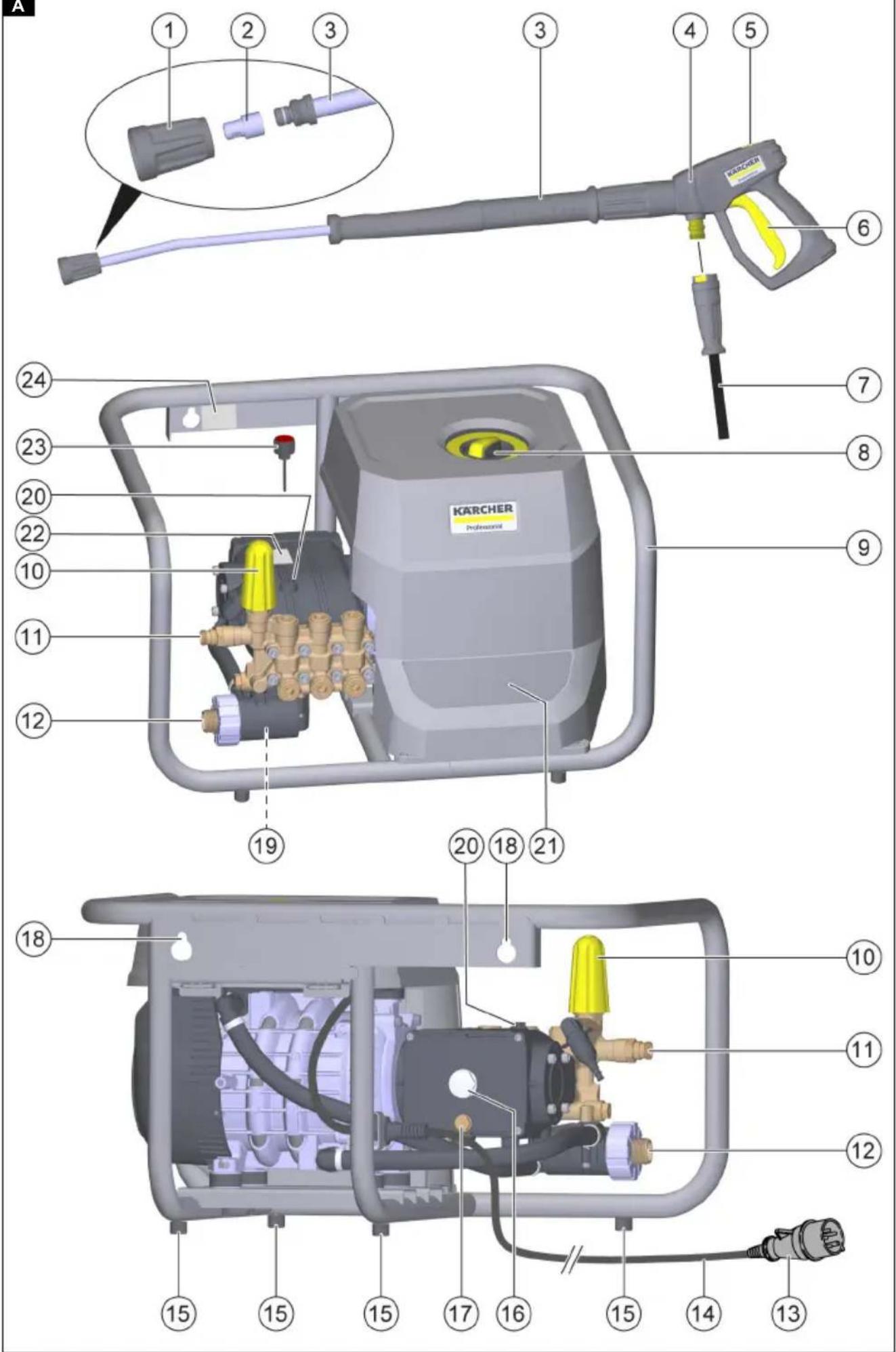
Device description
Overview of the device
Illustration A
① Union nut
② High-pressure nozzle
③ Spray lance EASY!Lock Classic
④ High-pressure gun EASY!LOCK Classic
⑤ Safety latch
⑥Trigger
⑦ High-pressure hose EASY!LOCK Classic
⑧ Power switch
⑨ Device frame
⑩ Pressure and quantity regulation
⑪EASY!Lock high-pressure connection
12 Water connection
⑬Mains plug
⑭ Mains cable
⑮Dowel stand (4 pieces)
⑯Oil level gauge
⑰Oil drain screw
⑱ Suspension eyelet
19 Fine filter
20 Plugs
21 Accessory compartment
②2Type plate (high-pressure pump)
23 Oil dipstick with breather valve
24Type plate (device)
Colour coding
- Control elements for the cleaning process are yellow.
- Control elements for maintenance and servicing are light grey.
Installation
Attach or set up the device
The device is suitable for wall mounting or as a standalone device.
Wall mounting
△DANGER
Risk of death and damage due to the device falling down!
There is a risk of death and damage if the device falls. Only mount the device on suitable, load-bearing walls. Be aware of the weight of the device during installation.
Use suitable lifting equipment or enlist the help of assistants.
Use suitable fasteners and ensure professional installation.
If in doubt, leave the installation to a person with specialist knowledge.
ATTENTION
Risk of damage due to frost!
An incompletely emptied device can be damaged by frost.
Protect the device from frost.
Operate or store the device in a frost-free place.
Completely empty the device and accessories before storing them.
-
Check the load-bearing capacity of the wall, taking into account the weight of the device, see chapter Technical data.
-
Check the space conditions, taking into account the dimensions of the device and appropriate clearances on all sides, see chapter Technical data.
-
Select suitable fasteners and mount the device horizontally on a vertical wall.
For dimensions and distances of the suspension eyes, see sketch.
Illustration E
Upright machine
- Place the device on a level, horizontal and solid surface on the four feet.
Connection of the high-pressure side to a permanently installed pipeline network
Note
The applicable national regulations for permanently installed high-pressure cleaning systems must be observed.
During installation, the specifications of the VDMA standard sheet 24416 "High-pressure cleaners; permanently installed high-pressure cleaning systems; terms, requirements, installation, testing" must be observed (available from Beuth Verlag, Cologne, www.beuth.de).
ATTENTION
Risk of damage due to pressure loss!
If the pressure loss in the high-pressure pipeline network is greater than in the 10 m standard high-pressure hose, the high-pressure pump can be damaged by overloading.
Fit a correspondingly larger high-pressure nozzle to compensate for the greater pressure loss.
- Lay the pipeline network to be permanently installed with as few changes of direction as possible.
Note
Observe the minimum cross-section of the pipelines: DN 15 ( 12 ).
- Route the pipeline network using padded loose and fixed clips to compensate for pressure and thermal expansion.
ATTENTION
Risk of damage due to vibration!
If the device is connected to the high-pressure pipeline network with a rigid pipe, vibrations may cause damage to the device or the high-pressure pipeline network.
Only connect the device to the high-pressure pipeline network using a high-pressure hose line.
- Connect the device to the pipeline network with a high-pressure hose line.
Note
Observe the minimum cross-section of the high-pressure hose line:
| Device Min. ∅ high pressure | hose line nominal width DN (in) |
| HD9/20-4 S ST Classic HD10/21-4 S ST Classic HD10/25-4 S ST Classic HD13/18-4 S ST Classic | DN 8 ( 14 ") |
| HD17/15-4 S ST Classic DN | 10 ( 38 ") |
Installing an oil dipstick with breather valve
ATTENTION
Risk of damage due to under- or overpressure!
If the plug is not replaced with the dipstick with breather valve before the initial startup, the high-pressure pump may be damaged.
Be sure to replace the plug with the dipstick with breath-er valve.
- Unscrew the plug and dispose of it.
Illustration B
① Plugs
② Oil dipstick with breather valve
- Screw in the dipstick with breather valve and tighten.
Checking / correcting the high-pressure pump oil level
ATTENTION
Risk of damage due to insufficient lubrication or unsuitable lubricants!
Too little oil or the use of unsuitable lubricants can damage the high-pressure pump.
Before the initial startup, ensure that the oil level in the high-pressure pump is sufficient and only fill with suitable lubricants.
ATTENTION
Risk of damage due to water in the oil!
If the oil is milky, there is water in the oil, which damages the high-pressure pump.
Do not operate the device with milky oil.
Contact Kärcher Service.
- Set up the device horizontally, see chapter Attach or set up the device.
Check the high-pressure pump oil level at the oil level indicator
- Check the oil level on the oil level indicator, it must be in the middle of the sight glass. If necessary, slowly top up oil, for specifications see chapter Technical data.
Check the high-pressure pump oil level with the dipstick with breather valve
-
Unscrew the dipstick with breather valve and wipe with a clean, lint-free cloth.
-
Insert the dipstick with the breather valve into the bore, do not screw it in. Illustration C
-
Pull out the dipstick with the breather valve and read the oil level, it must be between the MIN and MAX marks. If necessary, slowly top up oil, for specifications see chapter Technical data.
-
Wash your hands thoroughly with soap and water after each contact with oil.
Installing accessories
Note
The EASY!Lock system connects components quickly and safely via a single turn of the quick-release thread.
-
Connect the spray lance to the high-pressure gun and teh union nut and hand-tighten (EASY!Lock). Illustration D
-
Plug the high-pressure nozzle onto the spray lance.
-
Fit the union nut and hand-tighten (EASY!Lock).
-
Connect the high-pressure hose to the high-pressure gun and high-pressure connection of the device and tighten hand-tight (EASY!Lock).
Electrical connection
△DANGER
Risk of injury from electric shock
Use a plug to connect the device to the mains grid. Permanent connection to the mains grid is prohibited. The plug is used for mains isolation.
Only connect the device to an AC power source.
Use an extension cable with sufficient diameter (see "Technical data").
Unwind the extension cable completely from the cable drum.
-
Unwind the mains cable and place on the ground.
-
Plug the mains plug into the socket.
Water connection
Connection to a water line
⚠ WARNING
Health risk when operating without system separator!
When operating without an upstream system separator, there is a health risk due to backflow of contaminated water into the drinking water network.
Observe the regulations of your water supply company. Do not operate the device on the drinking water network without a system separator.
Use a system separator from KÄRCHER or a system separator as per EN 12729 Type BA. Water that has flowed through a system separator is classified as undrinkable.
Always connect the system separator to the water supply and never directly to the water connection on the device.
- Check that the pressure, temperature and quantity of the inlet water as well as the dimensions of the water inlet hose meet the requirements, see chapter Technical data.
- Connect the system separator and the water connection of the device with a water supply hose.
- Open the water inlet.
Sucking water from a container
- Screw the suction hose with filter onto the water connection (for the order number see chapter Technical data).
- Vent the device (see chapter Vent the device).
Vent the device
- Unscrew the high-pressure nozzle from the spray lance.
- Allow the device to run until the escaping water is free of air bubbles.
- In the case of venting problems, allow the device to run for 10 seconds and then switch it off. Repeat the procedure several times.
- Switch off the device.
- Screw the high-pressure nozzle onto the spray lance.
Operation
△DANGER
Danger of death when touching damaged, live parts!
When using damaged mains plugs, mains cables and extension cables, there is a danger of death due to electric shock!
Check the mains plug, mains cable and extension cable for damage before each use and only use them if they are in perfect condition.
Have damaged parts replaced immediately by a person with specialist knowledge.
⚠ WARNING
Risk of injury from high-pressure jet!
A high-pressure jet can escape from a defective device and accessories, or in the event of incorrect installation, and cause serious injuries.
Check the device and accessories for damage and faults in the installation before each use.
Have any damage repaired immediately and only use the device and accessories if they are in perfect condition and correctly installed.
⚠ WARNING
Risk of injury from high-pressure jet!
A high-pressure jet can escape from the pressurised device and accessories and cause serious injuries. Hold the high-pressure gun and spray lance tight with both hands.
Do not fasten the trigger in the actuated position.
Depressurise the device and disconnect the mains plug from the mains socket before releasing, dismantling or fitting the high-pressure hose or the high-pressure gun or carrying out work on the device or accessories.
Push the safety latch on the high-pressure gun forwards before releasing, dismantling or fitting the spray lance, jet nozzle or accessories (e.g. T-Racer, cup foam lance).
High-pressure operation
Note
The device is equipped with a pressure switch. The motor only starts when the trigger is pulled.
- Before each operation, check the device for damage and leaks, see chapter Each time before use.
- Set the trigger to the "I/ON" position.
-
Push the safety latch backwards. The high-pressure gun is unlocked.
-
Pull the trigger.
-
Adjust (infinitely adjustable) the working pressure and water quantity by turning the pressure and quantity regulator (+/-).
Operation with detergent
⚠ WARNING
Health risk when incorrectly handling detergents! Incorrect handling of detergents can endanger your health and the health of others.
Observe the safety and application instructions of the detergent manufacturers and act accordingly.
ATTENTION
Risk of damage when incorrectly handling detergents!
Incorrect handling of detergents can damage the device, accessories and treated objects.
Use only detergents approved by KÄRCHER.
Observe the safety and application instructions of the detergent manufacturers and act accordingly.
Follow the instructions on dosing and contact time.
Use detergents sparingly to help conserve the environment.
Note
KÄRCHER detergents ensure fault-free operation. Ask us for a consultation, request our catalogue or our detergent information sheets.
Note
The application of detergents with the device is possible with optional accessories, e.g. dosing unit, cleaning agent injector, cup foam lance.
Please educate yourself or ask for advice.
Operation with cup foam lance
- Unscrew the container. Illustration F
① Container
② Foam nozzle
③ High-pressure gun
④ Suction hose
⑤ Gate
Admixture: 3=high, 2=medium, 1=low
- Plug the desired gate into the suction hose.
- Fill the detergent into the container.
- Screw the container onto the foam nozzle.
- Disconnect the spray lance from the high-pressure gun.
- Connect the cup foam lance to the high-pressure gun and hand-tighten.
- Start up the high-pressure cleaner.
Recommended cleaning method
- Spray the detergent sparingly on the dry surface and let it work for a while (do not let it dry).
- Rinse off the loosened dirt with the high-pressure jet.
After operating with detergent
The cup foam lance must be flushed after use to prevent the formation of detergent deposits.
- Unscrew the container.
- Pour the remaining detergent back into the original packaging.
- Fill the container with clear water.
- Screw the container onto the cup foam lance nozzle.
- Operate the cup foam lance for approx. 1 minute to flush the detergent residue.
- Empty the container.
Interrupting operation
- Release the trigger.
The device switches off. - Push the safety latch forwards.
The high-pressure gun is secured.
Continuing operation
-
Push the safety latch backwards. The high-pressure gun is unlocked.
-
Actuate the trigger.
The device switches on.
Ending operation
- Close the water inlet.
- Actuate the trigger.
- Set the trigger to "I/ON" and allow the device to run for 5-10 seconds.
- Release the trigger.
- Set the power switch to "0/OFF".
- Pull the mains plug out of the socket only when your hands are dry.
- Dismantle the water supply hose on the water connection of the device.
- Actuate the trigger until the device is completely depressurised.
- Push the safety latch forwards. The high-pressure gun is secured.
Transport
△CAUTION
Risk of injury or damage due to non-observance of the weight!
When transporting and storing the device, there is a risk of injury and damage due to its weight.
Take into account the weight of the device for transportation and storage, see chapter Technical data.
Note
At least one helper is required to lift or carry the device.
- Transporting the device:
a Lift up and carry the device by the device's frame.
b Place the device on a suitable means of transport (e.g. platform truck) and secure it against slipping and tipping.
c When transporting in vehicles, secure the device against rolling away, slipping and tipping according to the respectively applicable guidelines.
Storage
△CAUTION
Risk of injury or damage due to non-observance of the weight!
When transporting and storing the device, there is a risk of injury and damage due to its weight.
Take into account the weight of the device for transportation and storage, see chapter Technical data.
ATTENTION
Risk of damage due to frost!
Water that is not completely drained can damage the device and accessories during freezing.
Empty the water completely from the device and accessories.
Protect the device and accessories from frost.
Store device
- Finish operation, see chapter Ending operation.
- Dismantle the high-pressure hose or the high-pressure hose line at the high-pressure connection of the device, see chapter Installing accessories.
- Remove the high-pressure hose from the high-pressure gun, see chapter Installing accessories.
- Allow the water to drain completely from the high-pressure hose and the high-pressure gun with spray lance.
- Pull the mains plug out of the socket only when your hands are dry.
- Store the device and accessories in a frost-protected interior space.
Flushing device with antifreeze
If frost-free storage is not possible:
- Close the water inlet.
- Dismantle the water supply hose on the water connection of the device.
- Let the water run out of the device.
- Pump commonly available anti-freeze through the device.
Note
Use commonly available, Glycol-based vehicle anti-freeze. Observe the handling instructions of the anti-freeze manufacturer.
- Turn the power switch to the "I/ON" position.
- Operate the trigger lever for max. 1 min until the anti-freeze is expelled from the device.
- Turn the power switch to the "0/OFF" position.
- Dismantle the high-pressure hose or the high-pressure hose line at the high-pressure connection of the device, see chapter Installing accessories.
- Remove the high-pressure hose from the high-pressure gun, see chapter Installing accessories.
-
Allow the water to drain completely from the high-pressure hose and the high-pressure gun with spray lance.
-
Pull the mains plug out of the socket only when your hands are dry.
- Store the appliance and accessories in an interior space.
Care and service
△DANGER
Inadvertently starting up device
Risk of injury, electric shock
Switch off the device immediately and unplug the mains plug before performing work.
Note
Old oil may only be disposed of at designated collection points. Please dispose of any old oil at these locations. Polluting the environment with old oil is punishable by law.
Safety inspection/maintenance contract
You can agree on regular safety inspections or close a maintenance contract with your dealer. Please seek advice on this.
Maintenance intervals
Each time before use
- Check the mains plug, the mains cable and the extension cables for damage.
Have damaged parts replaced immediately by the authorised Customer Service or a qualified electrician. - Check the high-pressure hose, high-pressure gun, jet pipe and accessories for damage. Replace damaged parts immediately.
- Check the device for leaks.
3 drops of water loss per minute are permissible. Contact Customer Service in the case of more serious leaks.
Weekly
ATTENTION
Risk of damage due to water in the oil!
If the oil is milky, there is water in the oil, which damages the high-pressure pump.
Do not operate the device with milky oil.
Contact Kärcher Service.
- Check the oil level of the high-pressure pump, see chapter Checking / correcting the high-pressure pump oil level.
- Clean the fine filter, see chapter Cleaning the fine filter.
Every 500 operating hours, at least annually
● Have the device serviced by Customer Service.
- Change the high-pressure pump oil, see chapter Change high pressure pump oil.
Cleaning the fine filter
- Close the water inlet.
- Depressurise the device, see chapter Ending operation.
- Unscrew the union nut. Illustration G
① Fine filter housing
② Fine filter
③ Connection nozzle
④ Union nut
-
Pull out the connection nozzle.
-
Pull the fine filter out of the fine filter housing.
- Rinse the fine filter with clear water or blow it out with compressed air.
- Insert the fine filter into the filter housing.
- Attach the connection nozzle.
- Tighten the union nut hand-tight.
Change high pressure pump oil
ATTENTION
Risk of damage when draining the high-pressure pump oil!
Draining the oil during operation damages the high-pressure pump.
Do not unscrew the oil drain screw while the device is in operation.
- Set the power switch to "0/OFF".
△WARNING
Risk of scalding!
The high-pressure pump oil can be very hot and cause scalding.
Allow the device to cool down before draining the high-pressure pump oil.
-
Allow the device to cool down.
-
Place a suitable container (oil-resistant, capaci ty min. 1.5 l) under the oil drain screw. The device must stand horizontally, see chapter Attach or set up the device.
Illustration H
① Oil dipstick with breather valve
② Oil level gauge
③ Oil drain screw
-
Unscrew the oil drain screw counter-clockwise using a ring or socket spanner with a spanner.
-
Allow the high-pressure pump oil to drain completely.
-
Replace the sealing ring on the drain screw.
-
Turn the drain screw clockwise and tighten it.
-
Filling new oil, see chapter Checking / correcting the high-pressure pump oil level.
-
Dispose of the old oil in accordance with the environmental and local regulations.
-
Wash your hands thoroughly with soap and water after each contact with oil.
Troubleshooting guide
DANGER
Inadvertently starting up device, touching live components
Risk of injury, electric shock
Switch off the device before performing any work on the device.
Remove the mains plug.
Have all checks and work on electrical parts performed by a qualified electrician.
In case of any malfunctions not mentioned in this chapter, contact the authorised Customer Service.
The device cannot be started
- Check the mains cable for damage.
- Check the mains voltage.
-
If the device overheats:
a Set the power switch to "0/OFF".
b Allow the device to cool for at least 15 minutes.
c Set the trigger to the "I/ON" position. -
Contact Customer Service in the case of electrical faults.
Device does not reach required pressure
- Check that the high-pressure nozzle is the right size (see chapter "Technical data").
- Clean or replace the nozzle.
- Vent the device (see chapter "Venting the water connection/device.").
- Clean the fine filter, replace if necessary (see chapter "Care and Maintenance/Weekly").
- Check the water supply volume (compare with the required volume specified in the "Technical data" chapter).
- Contact Customer Service if necessary.
The water quantity is too low
- When using a long high-pressure hose or a high-pressure hose with a small diameter, fit a larger high-pressure nozzle to the spray lance.
The pump is leaking.
Up to 3 drops of water per minute are permissible.
- In case of more serious leaks, have the device checked by Customer Service.
The pump knocks
- Check the water supply volume (compare with the required volume specified in the "Technical data" chapter).
- Vent the device (see chapter "Venting the water connection/device.").
-
Clean the fine filter, replace if necessary (see chapter "Care and Maintenance/Weekly").
-
Contact Customer Service if necessary.
The detergent dosing volume is too low
- Check that the cup foam lance used matches the flow rate of the device.
- Refill the cup of the cup foam lance.
- Plug a larger gate onto the suction hose.
- Check the suction hose and cup foam nozzle for detergent deposits. Remove deposits using lukewarm water.
- Contact Customer Service if necessary.
The foam formation is too low
- Check that the cup foam lance used matches the flow rate of the device.
- Check the suction hose and cup foam lance for detergent deposits. Remove deposits using lukewarm water.
- Contact Customer Service if necessary.
Warranty
The warranty conditions issued by our sales company responsible apply in all countries. We shall remedy possible malfunctions on your device within the warranty period free of cost, provided that a material or manufacturing defect is the cause. In a warranty case, please contact your dealer (with the purchase receipt) or the next authorised customer service site.
(See overleaf for the address)
Technical data
| HD 9/20-4 S ST Classic | HD 10/21-4 S ST Classic | HD 10/25-4 S ST Classic | HD 13/18-4 S ST Classic | HD 17/15-4 S ST Classic | ||
| Country variant | ||||||
| Country EU EU EU EU EU | ||||||
| Electrical connection | ||||||
| Voltage | V | 400 | 400 | |||
| Phase ~ 3 3 3 3 3 | ||||||
| Frequency | Hz | 50 | 50 | 50 | 50 | 50 |
| Maximum permissible mains grid impedance | Ω - | - | 0.0452 | +j0.0283 | 0.0452 +j0.0283 | 0.0452 +j0.0283 |
| Power rating | kW | 7 8 8,8 8,8 9 | ||||
| Degree of protection | IPX5 | IPX5 | IPX5 | IPX5 | IPX5 | |
| Power protection (slow-blow, char. C) | A | 16 | 16 | 16 | 16 | 16 |
| Extension cable, 10 m | mm2 | 2,5 2,5 2,5 2,5 2,5 | ||||
| Extension cable, 30 m | mm2 | 4 | 4 | 4 | 4 | 4 |
| Water connection | ||||||
| Feed pressure (max.) | MPa | 1 1 1 1 1 | ||||
| Input temperature (max.) | °C | 60 | 60 | 60 | 60 | 60 |
| Input amount (min.) | l/min | 18 | 20 | 20 | 25 | 31,6 |
| Suction height (max.) | m | 0,5 | 0,5 | 0,5 | 0,5 | 0,5 |
| Minimum water supply hose length | m | 7,5 | 7,5 | 7,5 | 7,5 | 7,5 |
| Minimum water supply hose diameter | in | 1 | 1 | 1 | 1 | 1 |
| Suction filter order number | 4.730-012.0 | 4.730-012.0 | 4.730-012.0 | 4.730-012.0 | 4.730-012.0 | |
| Device performance data | ||||||
| Nozzle size of standard nozzle | 047 050 045 075 105 | |||||
| HD 9/20-4 S ST Classic | HD 10/21-4 S ST Classic | HD 10/25-4 S ST Classic | HD 13/18-4 S ST Classic | HD 17/15-4 S ST Classic | ||
| Water operating pressure with standard nozzle | M | P | a | 2 | 0 | 2 |
Operating pressure (max.) MPa 26 27 31 24 21
Water flow rate l/min 15 16,67 16,67 21,67 28,33
High-pressure gun recoil force N 50 57 63 69 85
High-pressure pump
| Oil type Engine oil Engine oil Engine oil Engine oil Engine oil | ||||||
| SAE viscosity grade | 15W-40 | 15W-40 | 15W-40 | 15W-40 | 15W-40 | |
| Filling quantity | I | 0,65 | 0,65 | 0,65 | 0,65 | 1,2 |
Dimensions and weights
| Typical operating weight | kg | 44,8 | 48,4 | 54,4 | 54,4 | 59,2 |
| Length | mm | 720 | 720 | 720 | 720 | 720 |
| Width | mm | 522 | 522 | 522 | 522 | 522 |
| Height | mm | 418 | 418 | 418 | 418 | 418 |
Determined values in acc. with EN 60335-2-79
| Hand-arm vibration value | m/s^2 | 2,6 | 2,8 | 3,7 | 2,9 | 3,0 | |
| Uncertainty K | m/s^2 | 0,8 | 0,8 | 0,9 | 0,8 | 0,8 | |
| Sound pressure level L_pA | d | B | ( | A) | 7 | 1 | 6 |
| Uncertainty K_pA | dB(A) | 3 | 3 | 3 | 3 | 3 | |
| Sound power level L_WA + uncertain- ty K_WA | d | B | ( | A) | 8 | 6 | 8 |
Exception according to Regulation (EU) 2019/1781 Annex I Section 2 (12): j)
Subject to technical changes without notice.
Declaration of Conformity
EU Declaration of Conformity
We hereby declare that the machine described below complies with the relevant basic safety and health requirements in the EU Directives, both in its basic design and construction as well as in the version placed in circulation by us. This declaration is invalidated by any changes made to the machine that are not approved by us.
Product: High-pressure cleaner
Type: 1.367-xxx.x
Currently applicable EU Directives
2000/14/EC
2006/42/EC (+2009/127/EC)
2011/65/EU
2014/30/EU
2009/125/EC
Commission Regulation(s)
(EU) 2019/1781
Harmonised standards used
EN 60335-1
EN 60335-2-79
EN IEC 63000: 2018
EN 55014-1: 2017 + A11: 2020
EN 55014-2: 1997+A1: 2001+A2: 2008
EN 61000-3-2: 2014
EN 61000-3-3: 2013
HD 9/20-4 S St Classic
HD 10/21-4 S St Classic
EN 61000-3-11: 2000
HD 10/25-4 S St Classic
HD 13/18-4 S St Classic
HD 17/15-4 S St Classic
EN 62233: 2008
National standards used
Sound power level dB(A)
HD 9/20-4 S St Classic
Measured: 85
Guaranteed: 88
HD 10/21-4 S St Classic
Measured: 84
Guaranteed: 86
HD 10/25-4 S St Classic
Measured: 89
Guaranteed: 91
HD 13/18-4 S St Classic
Measured: 89
Guaranteed: 91
HD 17/15-4 S St Classic
Measured: 91
Guaranteed: 93
The signatories act on behalf of and with the authority of the company management.
H. Jenner
Chairman of the Board of Management
S. Reiser
Manager Regulatory Affairs & Certification
Documentation supervisor:
S. Reiser
Alfred Kärcher SE & Co. KG
Alfred-Kärcher-Str. 28 - 40
71364 Winnenden (Germany)
Ph.: +49 7195 14-0
Fax: +49 7195 14-2212
Winnenden, 2023/02/01
Declaration of Conformity (UK)
We hereby declare that the product described below complies with the relevant provisions of the following UK Regulations, both in its basic design and construction as well as in the version put into circulation by us. This declaration shall cease to be valid if the product is modified without our prior approval.
Product: High-pressure cleaner
Type: 1.367-xxx.x
Currently applicable UK Regulations
S.I. 2001/1701 (as amended)
S.I. 2008/1597 (as amended)
S.I. 2012/3032 (as amended)
S.I. 2016/1091 (as amended)
S.I. 2010/2617 (as amended)
Commission Regulation(s)
(EU) 2019/1781
Designated standards used
EN 60335-1
EN 60335-2-79
EN IEC 63000: 2018
EN 55014-1: 2017 + A11: 2020
EN 55014-2: 1997+A1: 2001+A2: 2008
EN 61000-3-2: 2014
EN 61000-3-3: 2013
HD 9/20-4 S St Classic
HD 10/21-4 S St Classic
EN 61000-3-11: 2000
HD 10/25-4 S St Classic
HD 13/18-4 S St Classic
HD 17/15-4 S St Classic
EN 62233: 2008
National standards used
Sound power level dB(A)
HD 9/20-4 S St Classic
Measured: 85
Guaranteed: 88
HD 10/21-4 S St Classic
Measured: 84
Guaranteed: 86
HD 10/25-4 S St Classic
Measured: 89
Guaranteed: 91
HD 13/18-4 S St Classic
Measured: 89
Guaranteed: 91
HD 17/15-4 S St Classic
Measured: 91
Guaranteed: 93
The signatories act on behalf of and with the authority of the company management.
H. Jenner
Chairman of the Board of Management

S. Reiser
Manager Regulatory Affairs & Certification
Documentation supervisor:
S. Reiser
Alfred Kärcher SE & Co. KG
Alfred-Kärcher-Str. 28 - 40
71364 Winnenden (Germany)
Ph.: +49 7195 14-0
Fax: +49 7195 14-2212
Winnenden, 2023/02/01
Contenu

Chairman of the Board of Management

S. Reiser
Manager Regulatory Affairs & Certification
Responsable de la documentation : S. Reiser
Alfred Kärcher SE & Co. KG
Alfred-Kärcher-Str. 28 - 40
71364 Winnenden (Germany)
Chairman of the Board of Management

S. Reiser
Manager Regulatory Affairs & Certification
71364 Winnenden (Germany)
Tel.: +49 7195 14-0
Fax: +49 7195 14-2212
Winnenden, 01/02/2023
2006/42/CE (+2009/127/CE)
2011/65/UE
2014/30/UE
2009/125/CE
H. Jenner
Chairman of the Board of Management
S. Reiser
Manager Regulatory Affairs & Certification
71364 Winnenden (Germany)
Tel.: +49 7195 14-0
Fax: +49 7195 14-2212
Winnenden, 01/02/2023
Índice
2006/42/CE (+2009/127/CE)
2011/65/UE
2014/30/UE
2009/125/CE
Chairman of the Board of Management

S. Reiser
Manager Regulatory Affairs & Certification
H. Jenner
Chairman of the Board of Management

S. Reiser
Manager Regulatory Affairs & Certification
71364 Winnenden (Germany)
Tel.: +49 7195 14-0
Fax: +49 7195 14-2212
Winnenden, 2023/02/01
İçindekiler
2006/42/AT (+2009/127/AT)
2011/65/AB
2014/30/AB
2009/125/EG
Chairman of the Board of Management
S. Reiser
Manager Regulatory Affairs & Certification
Winnenden, 2023/02/01
Innehåll
Allmän information 70
Chairman of the Board of Management
S. Reiser
Manager Regulatory Affairs & Certification
D-71364 Winnenden (Germany)
Tfn: +49 7195 14-0
Fax: +49 7195 14-2212
Winnenden, 01.02.2023
Sisältö
Chairman of the Board of Management
S. Reiser
Manager Regulatory Affairs & Certification
71364 Winnenden (Germany)
Puh.: +49 7195 14-0
2006/42/EF (+2009/127/EF)
2011/65/EU
2014/30/EU
2009/125/EF
Chairman of the Board of Management
S. Reiser
Manager Regulatory Affairs & Certification
71364 Winnenden (Germany)
Tlf.: +49 7195 14-0
Winnenden, 2023/02/01
Indhold
2006/42/EF (+2009/127/EF)
2011/65/EU
2014/30/EU
2009/125/EF
Chairman of the Board of Management
S. Reiser
Manager Regulatory Affairs & Certification
71364 Winnenden (Germany)
Tlf.: +49 7195 14-0
Fax: +49 7195 14-2212
Winnenden, 2023/02/01
Sisukord
Üldised juhised 101
Tarvikute monteerimine
Märkus
Vee sisseimemine mahutist
Toode: Körgsurvepesur
Tüüp: 1.367-xxx.x
2006/42/EÜ (+2009/127/EÜ)
2011/65/EL
2014/30/EL
2009/125/EÜ
Chairman of the Board of Management
S. Reiser
Manager Regulatory Affairs & Certification
71364 Winnenden (Germany)
Tel: +49 7195 14-0
Winnenden, 2023/02/01
Saturs
H. Jenner
Chairman of the Board of Management
S. Reiser
Manager Regulatory Affairs & Certification
H. Jenner
Chairman of the Board of Management

S. Reiser
Manager Regulatory Affairs & Certification
2006/42/WE (+2009/127/WE)
2011/65/UE
2014/30/UE
2009/125/WE
H. Jenner
Chairman of the Board of Management
S. Reiser
Manager Regulatory Affairs & Certification
71364 Winnenden (Germany)
Tel.: +49 7195 14-0
Chairman of the Board of Management

S. Reiser
Manager Regulatory Affairs & Certification
Winnenden, 2023/02/01
Obsah
Obecné pokyny 142
2006/42/ES (+2009/127/ES)
2011/65/EU
2014/30/EU
2009/125/ES
H. Jenner
Chairman of the Board of Management

S. Reiser
Manager Regulatory Affairs & Certification
Winnenden, 2023/02/01
Obsah
Všeobecné upozornenia.... 150
2006/42/ES (+2009/127/ES)
2011/65/EÚ
2014/30/EÚ
2009/125/ES
H. Jenner
Chairman of the Board of Management
S. Reiser
Manager Regulatory Affairs & Certification
71364 Winnenden (Germany)
Tel.: +49 7195 14-0
Fax: +49 7195 14-2212
Winnenden, 01.02.2023
Kazalo
Splošna navodila.... 158
Namenska uporaba.... 158
Zaščita okolja 159
Pribor in nadomestni deli.... 159
Obseg dobave.... 159
Varnostna navodila.... 159
Opis naprave.... 159
Montaža 160
Električni priključek.... 161
2006/42/ES (+2009/127/ES)
2011/65/EU
2014/30/EU
2009/125/ES
Uporabljena(-e) uredba(-e)
(EU) 2019/1781
Chairman of the Board of Management
S. Reiser
Manager Regulatory Affairs & Certification
Winnenden, 1. 2. 2023
Cuprins
Directive UE relevante
2000/14/UE
2006/42/UE (+2009/127/UE)
2011/65/UE
2014/30/UE
2009/125/UE
Regulament(e) utilizat(e)
(UE) 2019/1781
Norme armonizate aplicate
EN 60335-1
EN 60335-2-79
EN IEC 63000: 2018
EN 55014-1: 2017 + A11: 2020
EN 55014-2: 1997+A1: 2001+A2: 2008
EN 61000-3-2: 2014
EN 61000-3-3: 2013
HD 9/20-4 S St Classic
HD 10/21-4 S St Classic
EN 61000-3-11: 2000
HD 10/25-4 S St Classic
HD 13/18-4 S St Classic
HD 17/15-4 S St Classic
EN 62233: 2008
H. Jenner
Chairman of the Board of Management

S. Reiser
Manager Regulatory Affairs & Certification
71364 Winnenden (Germania)
Tel.: +49 7195 14-0
Fax: +49 7195 14-2212
Winnenden, 2023/02/01
Sadržaj
Opće napomene.... 175
2006/42/EZ (+2009/127/EZ)
2011/65/EU
2014/30/EU
2009/125/EZ
Primijenjene uredbe
(EU) 2019/1781
Primijenjene uskladene norme
EN 60335-1
EN 60335-2-79
EN IEC 63000: 2018
EN 55014-1: 2017 + A11: 2020
EN 55014-2: 1997+A1: 2001+A2: 2008
EN 61000-3-2: 2014
EN 61000-3-3: 2013
HD 9/20-4 S St Classic
HD 10/21-4 S St Classic
EN 61000-3-11: 2000
HD 10/25-4 S St Classic
HD 13/18-4 S St Classic
HD 17/15-4 S St Classic
EN 62233: 2008
Primijenjene nacionalne norme
Razina zvučne snage dB(A)
HD 9/20-4 S St Classic
Izmjereno: 85
Zajamčeno: 88
HD 10/21-4 S St Classic
Izmjereno: 84
Zajamčeno: 86
HD 10/25-4 S St Classic
Izmjereno: 89
Zajamčeno: 91
HD 13/18-4 S St Classic
Izmjereno: 89
Zajamčeno: 91
HD 17/15-4 S St Classic
Izmjereno: 91
Zajamčeno: 93
H. Jenner
Chairman of the Board of Management
S. Reiser
Manager Regulatory Affairs & Certification
Opunomoćenik za dokumentaciju:
S. Reiser
Alfred Kärcher SE & Co. KG
Alfred-Kärcher-Str. 28 - 40
71364 Winnenden (Njemačka)
Tel.: +49 7195 14-0
Telefaks: +49 7195 14-2212
Winnenden, 01.02.2023.
Sadržaj
Opšte napomene.... 183
Namenska upotreba 183
Zaštita životne sredine 183
Pribor i rezervni delovi.... 183
Obim isporuke 183
Sigurnosne napomene 183
Opis uređaja 184
Montaža.... 184
Električni priključak.... 185
Priključak za vodu 186
Rukovanje 186
Transport 187
Skladištenje 187
Nega i održavanje 188
Pomoć kod smetnji 188
Garancija 189
Tehnički podaci.... 189
EU izjava o usklađenosti 190
Opšte napomene
Pre prve upotrebe, pročitajte originalna uputstva za upotrebu i priložene bezbednosne instrukcije. Postupajte u
skladu sa tim.
Sačuvajte obe knjižice za buduću upotrebu ili sledeće vlasnike.
Namenska upotreba
Ovaj visokopritisni čistač upotrebljavajte isključivo za sledeće radove:
- Čišćenje visokopritisnim mlazom bez sredstva za čišćenje (npr. fasada, terasa, baštenskih uređaja)
- Cišćenje mlazom niskog pritiska i sredstvom za čišćenje (npr. mašina, vozila, zgrada, alata) Potreban je opcioni pribor, npr. jedinica za doziranje, injektor deterdženta, šoljica za penu.
2006/42/EZ (+2009/127/EZ)
2011/65/EU
2014/30/EU
2009/125/EZ
Primenjena(e) odredba(e)
(EU) 2019/1781
Primenjene harmonizovane norme
EN 60335-1
EN 60335-2-79
EN IEC 63000: 2018
EN 55014-1: 2017 + A11: 2020
EN 55014-2: 1997+A1: 2001+A2: 2008
EN 61000-3-2: 2014
EN 61000-3-3: 2013
HD 9/20-4 S St Classic
HD 10/21-4 S St Classic
EN 61000-3-11: 2000
HD 10/25-4 S St Classic
HD 13/18-4 S St Classic
HD 17/15-4 S St Classic
EN 62233: 2008
Primenjene nacionalne norme
Nivo zvučne snage dB(A)
HD 9/20-4 S St Classic
Izmereno: 85
Garantovano: 88
HD 10/21-4 S St Classic
Izmereno: 84
Garantovano: 86
HD 10/25-4 S St Classic
Izmereno: 89
Garantovano: 91
HD 13/18-4 S St Classic
Izmereno: 89
Garantovano: 91
HD 17/15-4 S St Classic
Izmereno: 91
Garantovano: 93
Potpisnici deluju po nalogu i uz punomoć upravnog odbora.
H. Jenner
Chairman of the Board of Management

S. Reiser
Manager Regulatory Affairs & Certification
Lice ovlašćeno za dokumentaciju:
S. Reiser
Alfred Kärcher SE & Co. KG
Alfred-Kärcher-Str. 28 - 40
71364 Winnenden (Germany)
Tel.: +49 7195 14-0
Winnenden, 2023/02/01
Περιεχόμενα
Chairman of the Board of Management

S. Reiser
Manager Regulatory Affairs & Certification
71364 Winnenden (Germany)
Tηλ.: +49 7195 14-0
Φαξ: +49 7195 14-2212
Winnenden, 2023/02/01
Содержание
Chairman of the Board of Management
S. Reiser
Manager Regulatory Affairs & Certification
71364 Winnenden (Germany)
Тел.: +49 7195 14-0
Факс: +49 7195 14-2212
Chairman of the Board of Management
S. Reiser
Manager Regulatory Affairs & Certification
71364 Winnenden (Germany)
Тел.: +49 7195 14-0
Факс: +49 7195 14-2212
H. Jenner
Chairman of the Board of Management
S. Reiser
Manager Regulatory Affairs & Certification
71364 Winnenden (Germany)
Тел.: +49 7195 14-0
Факс: +49 7195 14-2212
Виненден, 2023/02/01
目录
一般性注意事项.... 228
按规定使用.... 228
环境保护.... 228
附件和备件.... 228
供货范围 228
安全提示.... 228
设备介绍.... 228
安装 229
电气连接.... 230
水接头 230
操作.... 230
运输.... 231
存放.... 231
维护和保养.... 231
故障排除.... 232
质量保证.... 232
技术规格.... 233
欧盟一致性声明.... 234
一般性注意事项


www.kaercher.com/REACH
附件和备件
2006/42/EC (-2009/127/EC)
2011/65/EU
2014/30/EU
2009/125/EC
应用法规
(欧盟) 2019/1781
应用的协调标准
EN 60335-1
EN 60335-2-79
EN 1EC 63000: 2018
EN 55014-1: 2017 + A11: 2020
EN 55014-2: 1997+A1: 2001+A2: 2008
EN 61000-3-2: 2014
EN 61000-3-3: 2013
HD 9/20-4 S St Classic
HD 10/21-4 S St Classic
EN 61000-3-11: 2000
IID 10/25-4 S St Classic
HD 13/18-4 S St Classic
HD 17/15-4 S St Classic
EN 62233: 2008
适用的国家标准
声功率级 dB(A)
HD 9/20-4 S St Classic
测得的:85
确保的:88
HD 10/21-4 S St Classic
测得的:84
确保的:86
HD 10/25-4 S St Classic
测得的:89
确保的:91
HD 13/18-4 S St Classic
测得的:89
确保的:91
HD 17/15-4 S St Classic
测得的:91
确保的:93
Chairman of the Board of Management
S. Reiser
Manager Regulatory Affairs & Certification
文档全权代表:
S. Reiser
Alfred Kärcher SE & Co. KG
Alfred-Kärcher-Str. 28 - 40
71364 Winnenden (德国)
电话:+49 7195 14-0
传真:+49 7195 14-2212
Winnenden, 2023/02/01
اليyanات الفنية
| HD 17/15-4S STClassic | HD 13/18-4S STClassic | HD 10/25-4S STClassic | HD 10/21-4S STClassic | HD 9/20-4 SST Classic | ||
| محموعة antibodies | ||||||
| البلا | ||||||
| IEUEUEUE | ||||||
| 400 | 400 | 400 | 400 | 400 | V | توصيل الطاقة |
| 3 | 3 | 3 | 3 | 3 | ~ | الفقطية |
| 50 | 50 | 50 | 50 | 50 | Hz | الطور |
| 0.0452+j0.0283 | 0.0452+j0.0283 | 0.0452+j0.0283 | - | - | Ω | التردد |
| 9 | 8,8 | 8,8 | 8 | 7 | kW | QTQAOA OSHKKA QCPOU MSSMOH BHA |
| IPX5 | IPX5 | IPX5 | IPX5 | IPX5 | QTQAOA TTOPSIL | |
| 16 | 16 | 16 | 16 | 16 | A | TQOQI HOMAYA |
| 2,52,52,52,52,52,52,52,52,52,52,52,52,52,52,52,52,52,52,52,52,52,52,52,52,52,52,52,52,52,52,52,52,52,5 | ||||||
| 4 | 4 | 4 | 4 | 4 | mm2 | QTQAOA LASTPTALLE 10 m |
| QTQAOA LAESTPTALLE 30 m | ||||||
| 1 | 1 | 1 | 1 | 1 | MPa | QTQAOA LADY |
| 60 | 60 | 60 | 60 | 60 | °C | QTQAOA LADY |
| 31,6 | 25 | 20 | 20 | 18 | l/min | QTQAOA LADY |
| 0,5 | 0,5 | 0,5 | 0,5 | 0,5 | m | QTQAOA LADY |
| 7,5 | 7,5 | 7,5 | 7,5 | 7,5 | m | QTQAOA LADY |
| 1 | 1 | 1 | 1 | 1 | in | QTQAOA LADY |
| 4.730-012.0 | 4.730-012.0 | 4.730-012.0 | 4.730-012.0 | 4.730-012.0 | QTQAOA LADY | |
| QTQAOA LADY | ||||||
| 105 | 075 | 045 | 050 | 047 | QTQAOA LADY | |
| 15 | 18 | 25 | 21 | 20 | MPa | QTQAOA LADY |
| 21 | 24 | 31 | 27 | 26 | MPa | QTQAOA LADY |
| 28,33 | 21,67 | 16,67 | 16,67 | 15 | l/min | QTQAOA LADY |
| 85 | 69 | 63 | 57 | 50 | N | QTQAOA LADY |
| QTQAOA LADY | ||||||
| QTQAOA LADY | QTQAOA LADY | |||||
| 15W-40 | 15W-40 | 15W-40 | 15W-40 | 15W-40 | QTQAOA LADY | |
| 1,2 | 0,65 | 0,65 | 0,65 | 0,65 | l | QTQAOA LADY |
| QTQAOA LADY | ||||||
| 59,2 | 54,4 | 54,4 | 48,4 | 44,8 | kg | QTQAOA LADY |
| 720 | 720 | 720 | 720 | 720 | mm | QTQAOA LADY |
| 522 | 522 | 522 | 522 | 522 | mm | QTQAOA LADY |
| 418 | 418 | 418 | 418 | 418 | mm | QTQAOA LADY |
| QTQAOA LADY | ||||||
| QTQAOA LADY | ||||||
| QTQAOA LADY | ||||||
| QTQAOA LADY | ||||||
| QTQAOA LADY | ||||||
| QTQAOA LADY | ||||||
| QTQOOA LADY | ||||||
| QTQOOA LADY | ||||||
| QTQOOA LADY | ||||||
| QTQOOA LADY | ||||||
| QTQOOA LADY | ||||||
| QTQOOA LADY | ||||||
| QTQOOA LAD Y | ||||||
| QTQOOA LADY | ||||||
| QTQOOA LADY | ||||||
| QTQOOA LADY | ||||||
| QTQOOA LADY | ||||||
| QTQOOA LADY | ||||||
| QTQOOA LADY | ||||||
②Item 2: It is a simple diagram of a figure.
ياء واسحبه 2.
natural_image
Black and white line drawing of a hand giving a thumbs-up gesture (no text or symbols)THANK YOU!
MERCI! DANKE! iGRACIAS!

Register your product and benefit from many advantages.
www.kaercher.com/welcome


Rate your product and tell us your opinion.
natural_image
Icon showing a gear and wrench inside a square frame (no text or symbols)www.kaercher.com/dealersearch
Alfred Kärcher SE & Co. KG
Alfred-Kärcher-Str. 28-40
71364 Winnenden (Germany)