WSI 65TU - Heat pump DIMPLEX - Free user manual and instructions
Find the device manual for free WSI 65TU DIMPLEX in PDF.
| Product type | Brine/water heat pump |
| Brand | Dimplex |
| Model | WSI 65TU |
| Power supply | ~230 V / 50 Hz |
| Operating temperature range | -10 °C to 110 °C |
| Heat generator circuit pump (M16) | Magna3 40-80F |
| Intermediate circuit pump (M11) | Magna3 65-80F |
| Well water pump (M11) | To be provided on site |
| Heat exchanger | Bolted stainless steel plate heat exchanger |
| Frost protection | Capillary thermostat RAT 060I |
| Flow switch | DFS (installed in the primary circuit) |
| Expansion vessel | 25 liters |
| Hydraulic connection | Flanges, threaded pipes |
| Input signal | 0–10 V for pumps |
| Dirt collector | 2 ½" |
| Pressure relief valve | DN 25 |
| Pressure gauge | Included |
| Bonnet valve | DN 20 ¾" |
| Installation | Indoor or outdoor (diffusion-tight insulation recommended) |
| Maintenance | Bleeding circuits, checking seals, tightening heat exchanger |
| Safety | Frost protection, flow switch, shut-off valves |
Frequently Asked Questions - WSI 65TU DIMPLEX
User questions about WSI 65TU DIMPLEX
0 question about this device. Answer the ones you know or ask your own.
Ask a new question about this device
Download the instructions for your Heat pump in PDF format for free! Find your manual WSI 65TU - DIMPLEX and take your electronic device back in hand. On this page are published all the documents necessary for the use of your device. WSI 65TU by DIMPLEX.
USER MANUAL WSI 65TU DIMPLEX
Installation and Operating Instructions
DC intermediate circuit package for brine-to-water heat pump for using ground water as a heat source
natural_image
Close-up of a GRUNFOS industrial pump with attached black connector (no visible text or symbols)Magna3 40-80F bis Magna3 65-100F
1 Assembly, installation and safety instructions....GB-2
1.1 Hydraulic integration: GB-3
1.2 Screwed stainless steel plate heat exchanger.... GB-3
1.3 Connecting the heat generator and brine (intermediate) circuit pump: GB-4
1.4 Connection supply voltage \~ 230 V....GB-6
1.5 Connection input signal 0 – 10V GB-7
1.6 Frost protection thermostat (T) and flow rate switch (FS)......GB-7
1 Assembly, installation and safety instructions
flowchart
graph LR
    A["WP"] --> B["2"]
    B --> C["3"]
    C --> D["4"]
    D --> E["3"]
    E --> F["5"]
    F --> G["6"]
    G --> H["7"]
    H --> I["8"]
    I --> J["1"]
    style A fill:#f9f,stroke:#333
    style J fill:#ccf,stroke:#333
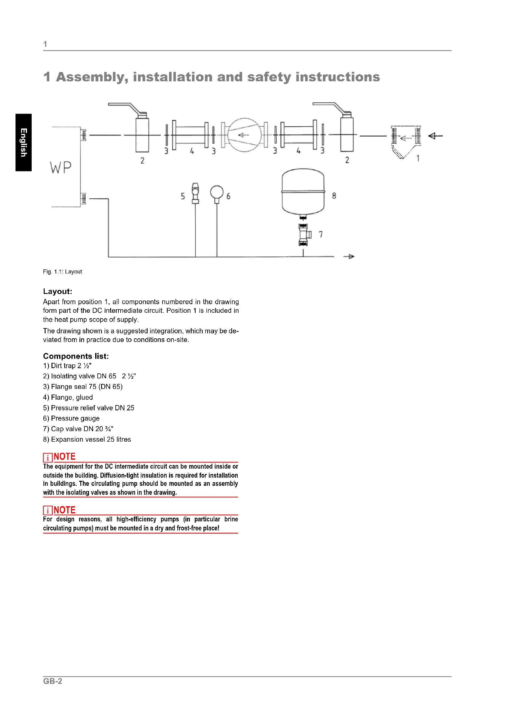
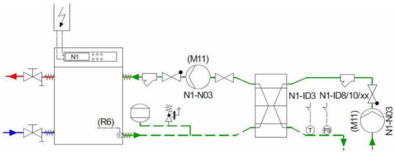
Fig. 1.1: Layout
Layout:
Apart from position 1, all components numbered in the drawing form part of the DC intermediate circuit. Position 1 is included in the heat pump scope of supply.
The drawing shown is a suggested integration, which may be deviated from in practice due to conditions on-site.
Components list:
1) Dirt trap 2 12 "
2) Isolating valve DN 65 2 1/2"
3) Flange seal 75 (DN 65)
4) Flange, glued
5) Pressure relief valve DN 25
6) Pressure gauge
7) Cap valve DN 20 ^3/4 "
8) Expansion vessel 25 litres
NOTE
The equipment for the DC intermediate circuit can be mounted inside or outside the building. Diffusion-tight insulation is required for installation in buildings. The circulating pump should be mounted as an assembly with the isolating valves as shown in the drawing.
NOTE
For design reasons, all high-efficiency pumps (in particular brine circulating pumps) must be mounted in a dry and frost-free place!
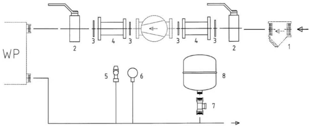
1.1 Hydraulic integration:
flowchart
graph TD
    A["Valve 1"] --> B["Component Unit (R6)"]
    C["Valve 2"] --> B
    B --> D["Valve 3"]
    D --> E["Valve 4"]
    E --> F["Valve 5"]
    F --> G["Valve 6"]
    G --> H["Valve 7"]
    H --> I["Valve 8"]
    I --> J["Valve 9"]
    J --> K["Valve 10"]
    K --> L["Valve 11"]
    L --> M["Valve 12"]
    M --> N["Valve 13"]
    N --> O["Valve 14"]
    O --> P["Valve 15"]
    P --> Q["Valve 16"]
    Q --> R["Valve 17"]
    R --> S["Valve 18"]
    S --> T["Valve 19"]
    T --> U["Valve 20"]
    U --> V["Valve 21"]
    V --> W["Valve 22"]
    W --> X["Valve 23"]
    X --> Y["Valve 24"]
    Y --> Z["Valve 25"]
    Z --> AA["Valve 26"]
    AA --> AB["Valve 27"]
    AB --> AC["Valve 28"]
    AC --> AD["Valve 29"]
    AD --> AE["Valve 30"]
    AE --> AF["Valve 31"]
    AF --> AG["Valve 32"]
    AG --> AH["Valve 33"]
    AH --> AI["Valve 34"]
    AI --> AJ["Valve 35"]
    AJ --> AK["Valve 36"]
    AK --> AL["Valve 37"]
    AL --> AM["Valve 38"]
    AM --> AN["Valve 39"]
    AN --> AO["Valve 40"]
    AO --> AP["Valve 41"]
    AP --> AQ["Valve 42"]
    AQ --> AR["Valve 43"]
    AR --> AS["Valve 44"]
    AS --> AT["Valve 45"]
    AT --> AU["Valve 46"]
    AU --> AV["Valve 47"]
    AV --> AW["Valve 48"]
    AW --> AX["Valve 49"]
    AX --> AY["Valve 50"]
    AY --> AZ["Valve 51"]
    AZ --> BA["Valve 52"]
    BA --> BB["Valve 53"]
    BB --> BC["Valve 54"]
    BC --> BD["Valve 55"]
    BD --> BE["Valve 56"]
    BE --> BF["Valve 57"]
    BF --> BG["Valve 58"]
    BG --> BH["Valve 59"]
    BH --> BI["Valve 60"]
    BI --> BJ["Valve 61"]
    BJ --> BK["Valve 62"]
    BK --> BL["Valve 63"]
    BL --> BM["Valve 64"]
    BM --> BN["Valve 65"]
    BN --> BO["Valve 66"]
    BO --> BP["Valve 67"]
    BP --> BQ["Valve 68"]
    BQ --> BR["Valve 69"]
    BR --> BS["Valve 70"]
    BS --> BT["Valve 71"]
    BT --> BU["Valve 72"]
    BU --> BV["Valve 73"]
    BV --> BW["Valve 74"]
    BW --> BX["Valve 75"]
    BX --> BY["Valve 76"]
    BY --> BZ["Valve 77"]
    BZ --> CA["Valve 78"]
    CA --> CB["Valve 79"]
    CB --> CC["Valve 80"]
    CC --> CD["Valve 81"]
    CD --> CE["Valve 82"]
    CE --> CF["Valve 83"]
    CF --> CG["Valve 84"]
    CG --> CH["Valve 85"]
    CH --> CI["Valve 86"]
    CI --> CJ["Valve 87"]
    CJ --> CK["Valve 88"]
    CK --> CL["Valve 89"]
    CL --> CM["Valve 90"]
    CM --> CN["Valve 91"]
    CN --> CO["Valve 92"]
    CO --> CP["Valve 93"]
    CP --> CQ["Valve 94"]
    CQ --> CR["Valve 95"]
    CR --> CS["Valve 96"]
    CS --> CT["Valve 97"]
    CT --> CU["Valve 98"]
    CU --> CV["Valve 99"]
    CV --> CW["Valve 100"]
Fig. 1.2: Hydraulic integration
1.2 Screwed stainless steel plate heat exchanger
Requirements on the installation area:
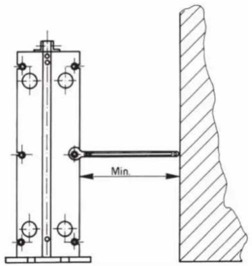
Sufficient space must be left free around the plate heat exchanger for maintenance (replacing plates, tightening the package). The free space should usually be around 1.5 to 2 x the width of the heat exchanger.
Transport, lifting the plate heat exchanger:
The heat exchanger is delivered screwed to a plate. The following points must be observed when lifting the device:
■ Remove the fixing screws from the pallet.
- Attach a strap around a bolt on each side. Never use steel cables or chains!
■ Lift the heat exchanger from the pallet, lower it horizontally onto its feet and position in its end position on solid ground, fix in place if necessary!
ATTENTION!
Never lift the heat exchanger by the connections or surrounding stud bolts!
Always use the lifting lugs (if present) or lift on the top side of the front pallet. Fix the straps onto their bolts for this.
Installation of the pipe connections:
ATTENTION!
When connecting the pipe system to the heat exchanger, ensure that it is not subjected to stress or strain by the pipe system! Clean the pipework before installation on the heat exchanger!
Heavy pipework must be supported to prevent strong forces from being applied on the heat exchanger.
Use flexible connections to prevent vibrations on the heat exchanger and to compensate for the expansion of the pipes caused by temperature fluctuations on the heat exchanger (tension-free lengthways installation).
i NOTE
To guarantee adequate venting, the bleeder valves should be mounted in the highest position in the flow direction of the medium (preferably on a pressure vessel). Isolating valves can be used on all connections of the heat exchanger to make them easier to open when necessary!
Threaded pipe connections:
During installation, ensure that these connections do not turn while pipe connectors or flanges are being mounted.
Turning the threaded pipe connections could damage the seal in the heat exchanger, which acts as a seal against the rear side of the pipe connection!
Flange connections:
If the connection is lined with rubber, the lining also acts as a flange seal. The connection flange should be connected directly to the end plate using the designated tapped holes. The screws should be tightened evenly - do not tighten excessively, as this could overwind the threads cut in to the frame plate.
If loose support flanges are mounted on the heat exchanger, a suitable seal is required for sealing the flange.
Commissioning:
ATTENTION!
Start the cold circuit first, followed by the hot circuit.
Purge the system completely by closing the isolating valves between the pump and the heat exchanger (if a valve is installed in the return of the heat exchanger, open it).
Then start the brine circulating pump and open the valves in the flow to the heat exchanger gradually.
If necessary, purge again and repeat the above steps for the secondary circuit if this is also a closed circuit.
1.3 Connecting the heat generator and brine (intermediate) circuit pump:
flowchart
graph TD
    A["Heating circuit(s)"] --> B["N1-N04 (E10.1)"]
    B --> C["3"]
    C --> D["Domestic hot water preparation"]
    D --> E["(M11) N1-N03"]
    E --> F["(M11) N1-N03"]
    F --> G["DDV"]
    G --> H["(M16)"]
    H --> I["(R2)"]
    I --> J["N1-B2 (R2)"]
    J --> K["DDV"]
    K --> L["DDV"]
    L --> M["DDV"]
    M --> N["DDV"]
    N --> O["DDV"]
    O --> P["DDV"]
    P --> Q["DDV"]
    Q --> R["DDV"]
    R --> S["DDV"]
    S --> T["DDV"]
    T --> U["DDV"]
    U --> V["DDV"]
    V --> W["DDV"]
    W --> X["DDV"]
    X --> Y["DDV"]
    Y --> Z["DDV"]
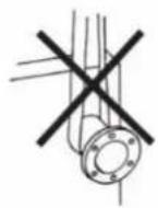
Fig. 1.3: Connecting the heat generator and brine (intermediate) circuit pump
| SI 50TUWSI 65TU | SI 75TUWSI 90TU | SI 90TUWSI 110TU | |
| Heat generator circuit pumpM 16: | Magna Geo 32-100VDC | Magna3 40-80F Magna3 | 65-80F |
| Intermediate circuit pumpM11: | Magna3 65-80F Magna3 | 65-100F Magna3 | 65-100F |
| Well pumpM11: | To be provided on-site | ||
i NOTE
The insulation shells provided may NOT be used on the heat source side (use as brine circulating pump M11)!
i NOTE
For design reasons, all high-efficiency pumps (in particular brine circulating pumps) must be mounted in a dry and frost-free place!
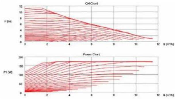
Technical data Magna Geo 32-100VDC
| Operating temperature range -10 °C to Installation length 180 mmPower consumption max. (P1) 175 WCurrent consumption max. (I1) 1.3 A | 10 °C |
Pump characteristic curve:
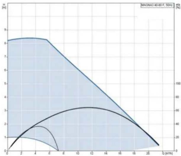
Technical data Magna3 40-80F
| Operating temperature range -10 °C to Installation length 220 mmPower consumption max. (P1) 265 WCurrent consumption max. (I1) 1.2 A | 10 °C |
Pump characteristic curve:
line
| Q (mm) | H [m] | mA [%] | | ------ | ----- | ------ | | 0 | 0 | 0 | | 2 | 1 | 20 | | 4 | 2 | 40 | | 6 | 3 | 60 | | 8 | 4 | 80 | | 10 | 5 | 100 | | 12 | 6 | 80 | | 14 | 7 | 60 | | 16 | 8 | 40 | | 18 | 9 | 20 | | 20 | 10 | 0 |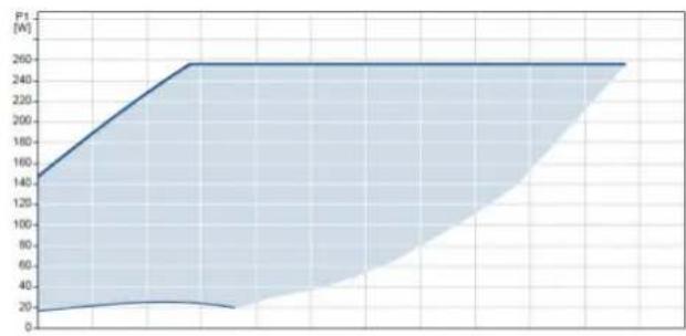
area
| Time (s) | Power (W) | | :--- | :--- | | 0 | 140 | | 1 | 160 | | 2 | 180 | | 3 | 200 | | 4 | 220 | | 5 | 240 | | 6 | 250 | | 7 | 250 | | 8 | 250 | | 9 | 250 | | 10 | 250 | | 11 | 250 | | 12 | 250 | | 13 | 250 | | 14 | 250 | | 15 | 250 | | 16 | 250 | | 17 | 250 | | 18 | 250 | | 19 | 250 | | 20 | 250 | | 21 | 250 | | 22 | 250 | | 23 | 250 | | 24 | 250 | | 25 | 250 | | 26 | 250 | | 27 | 250 | | 28 | 250 | | 29 | 250 | | 30 | 250 | | 31 | 250 | | 32 | 250 | | 33 | 250 | | 34 | 250 | | 35 | 250 | | 36 | 250 | | 37 | 250 | | 38 | 250 | | 39 | 250 | | 40 | 250 | | 41 | 250 | | 42 | 250 | | 43 | 250 | | 44 | 250 | | 45 | 250 | | 46 | 250 | | 47 | 250 | | 48 | 250 | | 49 | 250 | | 50 | 250 | | 51 | 250 | | 52 | 250 | | 53 | 250 | | 54 | 250 | | 55 | 250 | | 56 | 250 | | 57 | 250 | | 58 | 250 | | 59 | 250 | | 60 | 250 | | 61 | 250 | | 62 | 250 | | 63 | 250 | | 64 | 250 | | 65 | 250 | | 66 | 250 | | 67 | 250 | | 68 | 250 | | 69 | 250 | | 70 | 250 | | 71 | 250 | | 72 | 250 | | 73 | 250 | | 74 | 250 | | 75 | 250 | | 76 | 250 | | 77 | 250 | | 78 | 250 | | 79 | 250 | | 80 | 250 | | 81 | 250 | | 82 | 250 | | 83 | 250 | | 84 | 250 | | 85 | 250 | | 86 | 250 | | 87 | 250 | | 88 | 250 | | 89 | 250 | | 90 | 250 | | 91 | 250 | | 92 | 250 | | 93 | 250 | | 94 | 250 | | 95 | 250 | | 96 | 250 | | 97 | 250 | | 98 | 250 | | 99 | 250 | |100 | -140 |Technical data Magna3 65-80F
| Operating temperature range -10 °C to 110 °C | |
| Installation length 340 mm | |
| Power consumption max. (P1) 478 W | |
| Current consumption max. (I1) 2.12A | |
Pump characteristic curve:
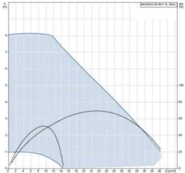
line
| Q (m³/h) | H [m/s] | Frequency [%] | | -------- | ------- | ------------- | | 0 | 1 | 0 | | 2 | 8 | 20 | | 4 | 8 | 40 | | 6 | 8 | 60 | | 8 | 8 | 80 | | 10 | 8 | 100 | | 12 | 8 | 80 | | 14 | 7 | 60 | | 16 | 6 | 40 | | 18 | 5 | 20 | | 20 | 4 | 10 | | 22 | 3 | 5 | | 24 | 2 | 2 | | 26 | 1 | 1 | | 28 | 0.5 | 0.5 | | 30 | 0.2 | 0.2 | | 32 | 0.1 | 0.1 | | 34 | 0.05 | 0.05 | | 36 | 0.02 | 0.02 | | 38 | 0.01 | 0.01 | | 40 | 0.005 | 0.005 |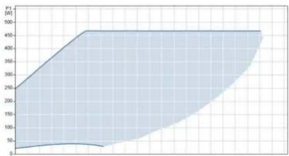
area
| Time | Power (W) | |------|-----------| | 0 | 250 | | 1 | 300 | | 2 | 350 | | 3 | 400 | | 4 | 450 | | 5 | 450 | | 6 | 450 | | 7 | 450 | | 8 | 450 | | 9 | 450 | | 10 | 450 | | 11 | 450 | | 12 | 450 | | 13 | 450 | | 14 | 450 | | 15 | 450 | | 16 | 450 | | 17 | 450 | | 18 | 450 | | 19 | 450 | | 20 | 450 | | 21 | 450 | | 22 | 450 | | 23 | 450 | | 24 | 450 | | 25 | 450 | | 26 | 450 | | 27 | 450 | | 28 | 450 | | 29 | 450 | | 30 | 450 | | 31 | 450 | | 32 | 450 | | 33 | 450 | | 34 | 450 | | 35 | 450 | | 36 | 450 | | 37 | 450 | | 38 | 450 | | 39 | 450 | | 40 | 450 | | 41 | 450 | | 42 | 450 | | 43 | 450 | | 44 | 450 | | 45 | 450 | | 46 | 450 | | 47 | 450 | | 48 | 450 | | 49 | 450 | | 50 | 450 | | 51 | 450 | | 52 | 450 | | 53 | 450 | | 54 | 450 | | 55 | 450 | | 56 | 450 | | 57 | 450 | | 58 | 450 | | 59 | 450 | | 60 | 450 | | 61 | 450 | | 62 | 450 | | 63 | 450 | | 64 | 450 | | 65 | 450 | | 66 | 450 | | 67 | 450 | | 68 | 450 | | 69 | 450 | | 70 | 450 | | 71 | 450 | | 72 | 450 | | 73 | 450 | | 74 | 450 | | 75 | 450 | | 76 | 450 | | 77 | 450 | | 78 | 450 | | 79 | 450 | | 80 | 450 | | 81 | 450 | | 82 | 450 | | 83 | 450 | | 84 | 450 | | 85 | 450 | | 86 | 450 | | 87 | 450 | | 88 | 450 | | 89 | 450 | | 90 | 450 | | 91 | 450 | | 92 | 450 | | 93 | 450 | | 94 | 450 | | 95 | 450 | | 96 | 450 | | 97 | 450 | | 98 | 450 | | 99 | 450 | |100* | (no label) |Technical data Magna3 65-100F
| Operating temperature range -10 °C to 110 °C | |
| Installation length 340 mm | |
| Power consumption max. (P1) 613 W | |
| Current consumption max. (I1) 2.7 A | |
Pump characteristic curve:
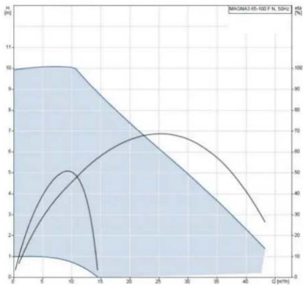
area
| Q (mmH) | H (m³) | | ------- | ------ | | 0 | 0 | | 5 | 10 | | 10 | 10 | | 15 | 0 | | 20 | 7 | | 25 | 7 | | 30 | 5 | | 35 | 3 | | 40 | 1 |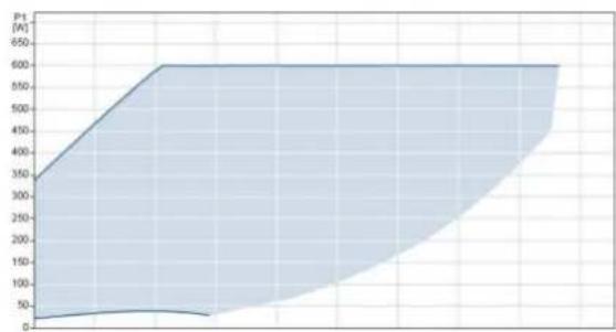
area
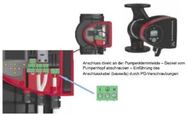
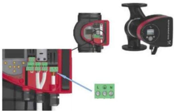
| Time | Power (A) | |------|-----------| | 0 | 0 | | 10 | 50 | | 20 | 100 | | 30 | 150 | | 40 | 200 | | 50 | 250 | | 60 | 300 | | 70 | 350 | | 80 | 400 | | 90 | 450 | | 100 | 500 | | 110 | 550 | | 120 | 600 | | 130 | 650 | | 140 | 700 | | 150 | 750 | | 160 | 800 | | 170 | 850 | | 180 | 900 | | 190 | 950 | | 200 | 1000 |1.4 Connection supply voltage \~ 230 V
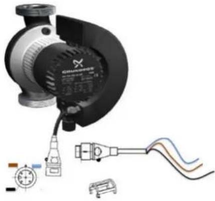
Magna Geo 32-100VDC

natural_image
Close-up of a GRUFOF motor with attached black connector and red arrow indicating rotation (no text or symbols on the motor body)Magna3 40-80F to Magna3 65-100F
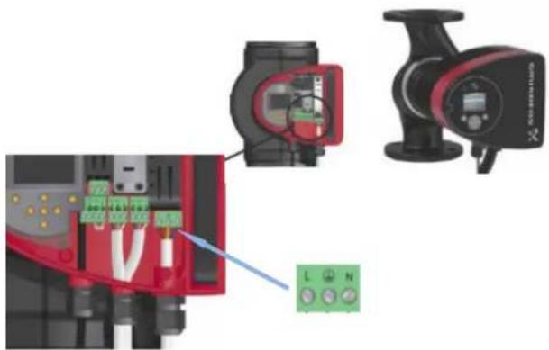
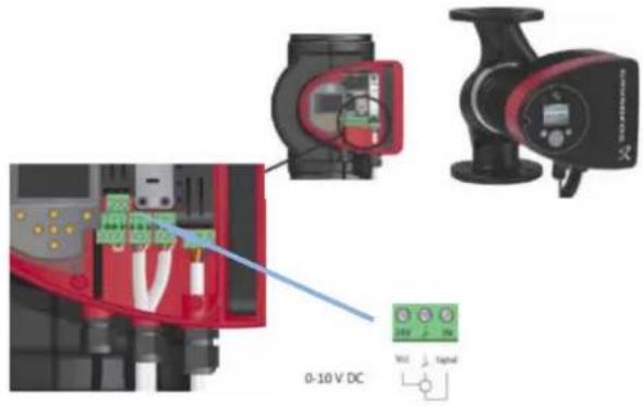
1.5 Connection input signal 0 - 10V
Magna Geo 32-100VDC
natural_image
Technical illustration of a mechanical pump assembly with wiring and connector components (no text or symbols)Magna3 40-80F to Magna3 65-100F
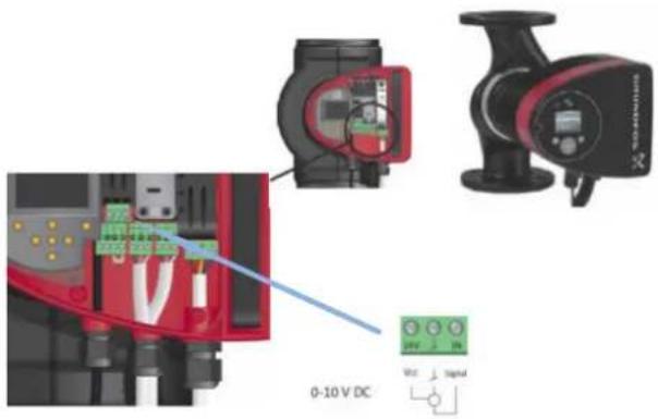
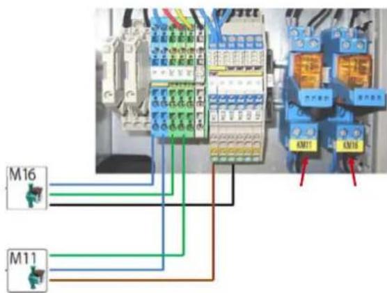
| Pump Terminal SignalM 16 J4/Y3 - X3 GND 0 - 10 VM 11 intermediate circuit pump J4/Y4 - X3 GND 0 - 10 VM 11 well pump Optional |

flowchart
graph TD
    A["PCOS"] --> B["WPH Reo36plm"]
    C["M16"] --> D["M11"]
    E["X3"] --> F["GND"]
    F --> G["G"]
1.6 Frost protection thermostat (T) and flow rate switch (FS)
Pipe-mounted thermostat RAT 060I (frost protection):
ATTENTION!
In order to ensure fault-free functioning of the device(s), the instructions given in the following text must be observed.
No temperature stratification must occur in the pipework at the installation site.
The surface of the pipe must be bare at the installation site and any paint or other insulation must be removed.
The tightening strap provided is inserted through the sensor base and pulled tight on the pipework. Excess lengths can be cut off.
■ The strap-on sensor must lie tightly against the pipe (use heat transfer compound if necessary)!
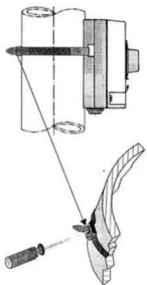
natural_image
Technical illustration of a mechanical assembly with tool and component details (no text or symbols)Switching function:
If the temperature reaches or falls short of the set setpoint of 4 °C, the changeover contact switches from terminal P1 - 2 to P1 - 1. If the temperature exceeds the setpoint by approx. 4 K, the changeover contact switches back again
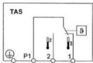
Connecting the frost protection thermostat (T) to the heat pump manager:
N1 ID 3 and X3 G / 24 V AC as

Contact in inactive state (no flow rate)
ATTENTION!
An additional flow rate switch installed in the primary circuit (FS) prevents the heat pump from switching on if the volume flow of the cooling water or ground water pump is not present.
Connecting the flow rate switch (FS) to the heat pump manager:
N1 ID 8/10/xx and X3 G
Table des matières
natural_image
Close-up of a GEUNDFOS industrial pump with a red arrow indicating compression or adjustment, showing internal components (no text or symbols on the pump body)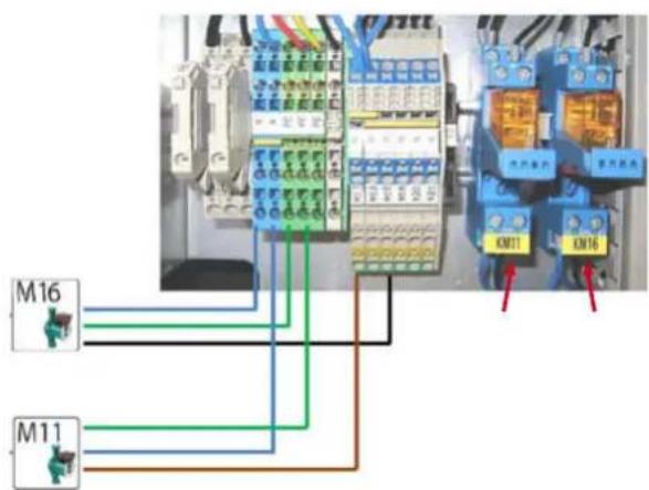
natural_image
Technical illustration of a mechanical pump assembly with wiring and connector components (no visible text or symbols)natural_image
Technical illustration of a mechanical assembly with a tool and pin, showing no text or symbols.natural_image
Close-up of a CRUDEOS industrial pump with attached black connector (no visible text or symbols)Da Magna3 40-80F a Magna3 65-100F

natural_image
Illustration of a motor with attached electrical connector and wiring (no text or symbols)Da Magna3 40-80F a Magna3 65-100F