
EDL170-520RF - Heat pump DIMPLEX - Free user manual and instructions
Find the device manual for free EDL170-520RF DIMPLEX in PDF.


| Product Type | Heat pump |
| Brand | Dimplex |
| Model | EDL170-520RF |
| Type | Air-to-water heat pump |
| Heating Capacity | 17 kW |
| Cooling Capacity | 14 kW |
| COP (A7/W35) | 4.5 |
| Power Supply | 400V/3N~50Hz |
| Refrigerant | R410A |
| Outdoor Unit Dimensions (HxWxD) | 1100 x 900 x 800 mm |
| Outdoor Unit Weight | 120 kg |
| Sound Level (Outdoor) | 55 dB(A) |
| Operating Temperature Range | -20°C to +35°C |
| Functions | Heating, cooling, domestic hot water |
| Control | Digital controller with LCD display |
| Safety Features | Overheat protection, frost protection, high-pressure switch |
| Maintenance | Clean filters regularly; check refrigerant pressure annually |
| Spare Parts Availability | Fan motor, compressor, expansion valve, sensors |
| Repairability | Modular design, accessible components |
| Certifications | CE, ETL, ISO 9001 |
Frequently Asked Questions - EDL170-520RF DIMPLEX
User questions about EDL170-520RF DIMPLEX
0 question about this device. Answer the ones you know or ask your own.
Ask a new question about this device
Download the instructions for your Heat pump in PDF format for free! Find your manual EDL170-520RF - DIMPLEX and take your electronic device back in hand. On this page are published all the documents necessary for the use of your device. EDL170-520RF by DIMPLEX.
USER MANUAL EDL170-520RF DIMPLEX
natural_image
Red smartphone with black outline and 'K-Deeplex' branding on screen (no additional text or symbols visible)DCDimplex
natural_image
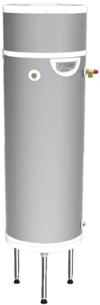
Exterior view of a cylindrical water heater with three legs and a side-mounted valve (no text or symbols visible)Air Source Heat Pump Water Heater
Installation and User Instructions

The Hot Water Association (HWA) Charter is a code of Practice which requires that all members adhere to the following:
• supply fit for purpose products clearly and honestly described
• supply products that meet, or exceed appropriate standards and building and water regulations
• provide pre and post sales technical support
• provide clear and concise warranty details to customers
For further information on HWA Charter Membership, please refer to HWA website www.hotwater.org.uk'
All cylinders are certified by KIWA, for further information on this regulation body please refer to the KIWA website www.kiwa.co.uk'
These products are tested in accordance with EN12897:2016
1 Manual Warnings 4
2 Safety Information 4
| 2.1 | User | Safety |
| 2.2 | General | Safety |
3 Introduction 5
3.1 Dimplex Control 5
4 Scope of Delivery 5
5 Pre-Installation Advice 5
| 5.1 | Handling | |
| 5.2 | Storage | |
| 5.3 | Unpacking | |
| 5.4 | Pipework | |
| 5.5 | Taps and Fittings | 6 |
| 5.6 | Risk Assessment | 6 |
| 5.7 | Siting Considerations | 6 |
| 5.8 | Installation | 7 |
| 5.8.1 | On-ground Installation | |
| 5.9 | Cold Water Supply | 7 |
| 5.10 | Building Regulation G3 Discharge Requirements | 7 |
| 5.10.1 | Discharge Pipe D2 | 7 |
| 5.10.2 | Worked Example | 8 |
| 5.10.3 | Termination of Discharge Pipe | |
| 5.11 | Product Disposal | |
6 Installation
| 6.1 | Correctly Siting the Water Heater | 9 |
| 6.2 | Cold Water Inlet with Inlet Group | 9 |
| 6.2.1 | Install the Inlet Group | 9 |
| 6.2.2 | Expansion Vessel | |
| 6.2.3 | Balanced Cold Water Supply | 10 |
| 6.2.4 | Drain Valve | |
| 6.3 | Hot Water Outlet | |
| 6.3.1 | Thermostatic Mixing Valve | 10 |
| 6.3.2 | Pipe Insulation | 10 |
| 6.4 | Discharge Pipes from Safety Devices | 10 |
| 6.4.1 | Discharge Pipe D1 | 10 |
| 6.4.2 | Discharge Pipe D2 | 10 |
| 6.4.3 | Tundish | |
| 6.5 | Immersion Heater | 10 |
| 6.6 | Air Connection | |
| 6.7 | Ducting Design | |
| 6.7.1 | Worked Example | 11 |
| 6.8 | Ducting Installation | 12 |
| 6.8.1 | Direct Access | |
| 6.8.2 | Offset Access | 12 |
| 6.8.3 | Distanced Access | |
| 6.9 | Fixing | 13 |
| 6.10 | Condensates Draining | 14 |
| 6.11 | Electrical Connections | 14 |
| 6.11.1 | Accessing Electrical Connections | 14 |
| 6.11.2 | Electricity Provider Contact | 14 |
7 Set-Up and Use 15
| 7.1 | Commissioning | 15 | |
| 7.2 | Using your Hot Water Heat Pump | 16 | |
| 7.3 | Control Box | 16 | |
| 7.4 | Setting the Language | 16 | |
| 7.5 | Setting the Time | 16 | |
| 7.6 | Setting the Water Temperature | 17 | |
| 7.7 | Holiday Mode | 17 | |
| 7.8 | BOOST Function(for occasional use) | 17 | |
| 7.9 | Electric Mode(to operate with electrical backup) | 17 | |
| 7.10 | Programming | 18 | |
| 7.11 | Installer Menu | 19 | |
| 7.11.1 | PV Mode | 19 | |
| 7.11.2 | Adjusting the Operating Settings | 19 | |
| 7.11.3 | Anti-bacteria | 20 | |
| 7.11.4 | Fan Mode | 20 | |
| 7.11.5 | Minimum Temperature | 20 | |
| 7.11.6 | Shedding | 2 | |
| 7.11.7 | Maximum Time | 21 | |
| 7.11.8 | Locking the keyboard | 21 | |
| 7.11.9 | Resetting Parameters | 21 | |
| 7.11.10 | Reading Display | 21 | |
| 7.11.11 | Counters | 2 |
8 Maintenance 22
| 8.1 | DHW Cylinder | 22 |
| 8.2 | Heat Pump | 22 |
| 8.3 | 9Air intake & Exhaust 23 | |
| 8.4 | Heat Pump Condensation 23 | |
| 8.5 | Electrical Connections 23 | |
| 8.6 | Troubleshooting | 24 |
| 8.7 | 9Spare Parts | 25 |
| 8.8 | Error Message Codes 26 | |
| 10 |
9 Control App 28
| 9.1 | Home Screen | 28 |
| 9.2 | Holiday Mode 28 | |
| 9.3 | Schedule Control 28 | |
| 9.4 | Hygiene Mode 28 |
10 Warranty 29
| 10.1.1 Warranty Limits | 29 |
| 10.1.1 Exclusion from Warranty | 29 |
| 11 | |
| 11 |
11 Technical Data and Product Fiche 30
12
13
1 Manual Warnings

Electrical Warnings
Indicates any hazard of an electrical nature.
Information

Indicates tips and advice for the smooth operation of the system.
General Warnings

Indicates a general warning against actions which could result in damage to the system or personal injury to the installer and/or user.
2 Safety Information
2.1 User Safety

This appliance can be used by children aged 8 years and above and persons with reduced physical, sensory or mental capabilities or lack of experience and knowledge if they have been given supervision or instruction concerning use of appliance in a safe way and understanding the hazards involved - some parts of this product can become hot and cause burns. Children shall not play with the appliance. Cleaning and user maintenance shall not be made by children without supervision.

The maintenance of this appliance must be carried out by suitable qualified person only. It is recommended to maintain the unit on an annual basis. Isolate all electrical supplies from the unit before commencing work. Danger of electrical shock!

The cylinder must be filled with water before switching on the immersion heater. Failure to do so will damage the element and void the warranty.

Do not handle a flame of flammable source near the appliance.
2.2 General Safety

The R290 refrigerant in the heat pump circuit poses no risk to the environment but is flammable.

Before removing the cover from the immersion heater isolate the appliance using isolating switch! Danger of electrical shock! Only use suitable electrically insulated equipment when working inside immersion housing.

The appliance should be installed in a place where it is not exposed to damp and is not at risk of being splashed with water.

It is important to check the pre-charge pressure of the expansion vessel membrane before filling the cylinder. This has been factory set to 3 bar. The pre-charge should be greater than or equal to 3 bar.

A high level cut-out is fitted to the product for each heat source. This should never activate under normal operation.

The appliance should be installed in an area where it is not exposed to humidity and without risk of being splashed by water.

Before installation the appliance must not be stored in an enclosed space of less than 4m^2 without ventilation.

It is strictly prohibited to release refrigerant gas into the atmosphere. The refrigerant must be collected before work is carried out on the

It is important that the tundish is positioned away from any electrical components.

Means for electrical disconnection must be incorporated in the fixed wiring in accordance with the wiring rules.

No isolating device may be fitted between the inlet group and the cold water inlet on the cylinder, as by doing so important safety devices could be isolated!
Please retain manual for future reference.

If an electronic copy of this manual should be required, please contact the manufacturer at the address at the back of this manual.
3 Introduction
Thank you for choosing this product. The Edel Air Source Heat Pump water heaters are specified with high quality, immersion heaters for fast reheat times. They boast 50mm of low GWP insulation foam, together with 100% recyclable stainless steel inner components and a hard wearing outer shell manufactured from completely recycled materials.

Dimplex cannot take responsibility for ensuring safe operation of the appliance outside of the scope of intended use.
3.1 Dimplex Control
This product is Dimplex Control capable * .
Control and monitor your heating and hot water with Dimplex Control. Group appliances into zones to easily control and track their energy usage. Any time. Anywhere. Search for Dimplex Control on your device's app store.



*A Dimplex Hub is required for this product to connect to Dimplex Control. For instruction on setting up Dimplex Hub, please refer to the manual online or section 9 in this manual. Manuals can be downloaded at www.Dimplex.co.uk.
4 Scope of Delivery
The appliance is delivered factory fitted with a T&P valve and immersion heater. The tripod is contained within the same package as the appliance. For the installation, two accessories boxes are required and are provided by Dimplex. A complete list of all items delivered is illustrated in Table 1
| Cylinder with 1.2Kw immersion |
| T+P valve |
| Tripod |
| Inlet control group consisting of:- In line strainer- 3 bar PRV- 6 bar ERV- Non-return valve- Balanced cold water supply port- Connection for expansion vessel |
| Expansion vessel with fixing kit and connection hose |
| Tundish |
| EDL Vent kit consisting of -∅80mm MF PVC elbow- ∅125mm sleeve 850mm- ∅80mm flexible tube 250mm- ∅80mm PVC ducting 1000mm- ∅125mm PVC ducting 400mm- ∅125mm half tee- Tee cover- ∅125mm insulated extension 850mm- Wall seal ring- Collar- Vent nozzle- Exterior seal- Drilling template |
| Installation & user instructions x 1 |
| Terms and conditions x 1 |
Table 1: Scope of Delivery for Edel Water Heater
Note:
This product has been designed specifically for the purpose of delivering heated, domestic and sanitary hot water as part of a pressurised water heating system. The package is provided with fittings that comply with Section G3 of Building Regulations.
5 Pre-Installation Advice
Please read the following section carefully before commencing installation. If in any doubt, please call the appropriate help desk. Disregarding the instructions given in this manual in its entirety and any relevant regulations, standards and codes of practice will void the guarantee of this product.
5.1 Handling
The upper covers of the appliance are not made to withstand force and should not be used for handling purposes.
Non-permitted transport positions:
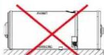

Transporting the appliance in a horizontal position may lead to irreparable damage to the components of the heat pump
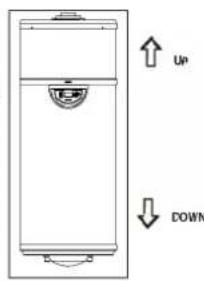
Permitted transport positions: Transport and handling of the appliance must be done in its original cardboard packaging using the handles integrated into the cardboard packaging for ease of transportation. Transport in a vehicle must be done with the appliance in a vertical position.

All other transport positions are PROHIBITED
If tipped, the centre of gravity will shift towards the top: handle with care.
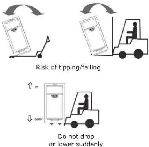
Please note that handling, installation and use of this product is subject to the Health and Safety at Work Act.
If the unit is not installed immediately, it should remain in its protective packaging with all pipe protectors/end caps applied to prevent damage and dirt deposit inside the water heater and the coil.
5.2 Storage
-The appliance must not be stored in an enclosed space of less than 4m^2 without ventilation.
-If the appliance is stored in a room with a surface area of less than 4m^2 (in a storage closet for example) there must be ventilation points at the top and bottom points of the space.
Admissible storage and transport temperatures of the heat pump water heater are from -5^ to +35^
5.3 Unpacking
- Remove plastic cover and cardboard packaging.
- Remove corner protection pieces, ensuring that all nails and staples are taken out.
- Remove protective film from all parts of the appliance and from the bag of accessories which you will find in the transport bag.
- Without tilting the appliance, use an appropriate tool to remove the screws from underneath the pallet.

Keep the transport bag out of reach of children (risk of suffocation).
5.4 Pipework
The pipe runs should be executed as short as possible, unused pipework should be removed and all remaining pipework should be lagged in accordance with regulatory requirements to prevent heat loss and the formation of condensation.
5.5 Taps and Fittings
All taps and fittings incorporated in the system should have a rated operating pressure of 0.6 MPa (6 bar) or above.
5.6 Risk Assessment
It is strongly recommended to complete a risk assessment before installing the product. The following areas require particular consideration in addition to the information required by the Health and Safety at Work Act.
- Scalding: where appropriate or required by law a thermostatic mixing valve is to be fitted.
- Explosion: the unit is fully equipped with all relevant safety equipment to comply with current regulations. The correct design and function has been verified by independent third party testing. The correct application hereafter is the responsibility of the competent installer.
- Water borne organisms (i.e. Legionella): if applicable a risk assessment should be carried out following the recommendations outlined in the Approved Code of Practice L8.
- The user preference must be considered when commissioning the system.
5.7 Siting Considerations
When choosing the place where the appliance is to be installed the following points should be taken into consideration:
- Structural integrity.
- Access for installation, operation, maintenance and replacement.
- Routing of discharge pipework.
- Access to water mains supply, hot and cold water distribution pipework.
- Access to suitable electricity supply.
It is PROHIBITED:
- To let the appliance operate using air intake which contains solvents or explosive matter.
- To use air intake which contains grease, dust or aerosol particles.
- To connect vented exhaust hoods to the ventilation system.
It is PROHIBITED to install the appliance
- Outdoors
- In rooms which are exposed to frost
- In humid rooms which have a lot of steam or vapour (for example, a bathroom)
- To install product directly onto floor, tripod MUST be used
The water heater may be located on any flat and level surface, provided it is sufficiently robust to support the weight of the water heater when full of water (please see technical data) and suitably accessible for replacement/maintenance without specialist tools or lift-
Particular care must be taken when placing the water heater in a garage or outbuilding. All exposed pipework must be correctly insulated to avoid frost damage.
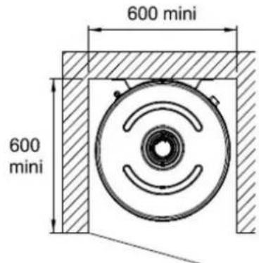
The position and orientation of the water heater should be such that easy access is provided for servicing the controls. A minimum distance of 400mm in front of the immersion is recommended, to allow the replacement of the immersion heater should the need arise. When installing the water heater all labels should be clearly visible and ensure that no pipework hinders any work to be carried out on the various components.
To facilitate the condensates flow, adjust the feet so that the appliance is vertical, see Figure 1.
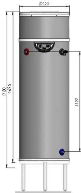
Figure 1: Correct siting of Water Heater

Once the heat pump water heater is installed in its definitive place, it is important to wait 15 minutes before turning the appliance on
5.8 Installation
5.8.1 On-ground Installation
A tripod, makes it able to install the heat pump water heater on the ground. The height of the tripod is adjustable from 300mm to 500mm. To adjust the tripod horizontally, each foot is equipped with an adjustment screw to be used for this purpose.
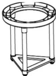
natural_image
Line drawing of a circular mechanical stand with triangular supports (no text or symbols)
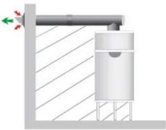
The heat pump water heater must be anchored to the wall to avoid any danger of tipping or falling.
natural_image
Diagram of a vertical cylindrical structure mounted on a wall, with diagonal hatching and directional arrows indicating flow or movement (no text or symbols)
Figure 2: Correct siting of Water Heater on tripod
5.9 Cold Water Supply
For satisfactory and safe performance of the water heater the water supply must meet the following criteria:
| Minimum dynamic pressure 150Kpa (1.5 bar) |
| Maximum inlet supply pressure 1200Kpa (12 bar) |
| Minimum flow rate 15l/min |
| Max. chlorine content 250mg/L |
| Max. water hardness 200mg/L |
The following instructions have to be followed when installing the cold water mains supply to the water heater:
- The cold water supply to the water heater must come directly from the cold water mains after the mains stop valve to the property.
- The cold water inlet pipework should have at least an inside diameter of 19mm and should meet the requirements of the water regulations for the supply of wholesome water.
Dimplex recommend an annual maintenance inspection is carried out on the water heater. In hard water areas this should include inspection of the immersion heater, [above 120ppm or 120mg/l]. A local water treatment company should be able to offer free water quality testing. The heating elements may require periodic de-scaling. The installer should do this as part of a maintenance agreement.
If required, precautions can be taken to minimise effects of water hardness, i.e. installation of water conditioner or water softener. These devices should be installed in hard water areas where high water storage temperatures are required, i.e. greater than 60°C storage temperatures, particularly when water hardness exceeds 200ppm. Should the water heater require de-scaling, this must be performed by a qualified technician.
Do not install the air intake nozzle near a vapour exhaust (minimum distance 0.6m).
5.10 Building Regulation G3 Discharge Requirements
As part of the requirements of Building Regulation G3 this product is factory fitted with a T&P valve, which complies with BS EN 1490. Any discharge from a water heater system should be conveyed to where it is visible, but will not cause danger to persons in or about the building. The tundish and the discharge pipes should be fitted in accordance with the requirements of Building Regulation approved document G3, (England and Wales), Part P of Northern Ireland and Standard 4.9 of Scotland.
5.10.1 Discharge Pipe D2
The discharge pipe (D2) from the Tundish should:
- "have a vertical section of pipe at least 300mm long below the tundish before any elbows or bends in the pipework and be installed with a continuous fall of at least 1 in 200 thereafter."
The discharge pipe (D2) should be made of:
- "metal; or other material that has been demonstrated to be capable of safely withstanding temperatures of the water discharged and is clearly and permanently marked to identify the product and performance standard".
Dimplex strongly recommends the use of metal pipework only and Dimplex does not take responsibility for any damage caused from discharges.
The discharge pipe D2 should be at least one pipe size larger than the nominal outlet size of the safety device unless its total equivalent hydraulic resistance exceeds that of a straight pipe 9m long, i.e. for discharge pipes between 9m and 18m the equivalent resistance length should be at least two sizes larger than the nominal outlet size of the safety device; between 18m and 27m at least 3 sizes larger, and so on; bends must be taken into account in calculating the flow resistance.
See Figure 3, Table 2 and the worked example.
Note: An alternative approach for sizing discharge pipes would be to follow Annex D, section D.2 of BS 6700:2006 + A1:2009).
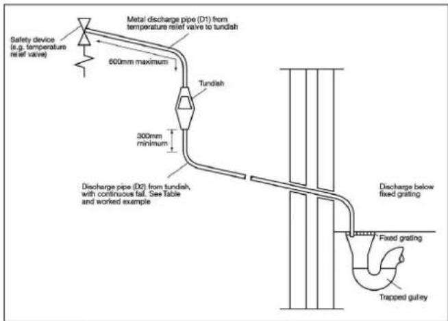
Figure 3: Typical discharge pipe arrangement
| Value outlet size | Minimum size of discharge pipe before tundish (mm) | Minimum size of discharge pipe after tundish (mm) | Maximum allowed length of pipe after tundish (m) | Length to be subtracted for each elbow or bend (m) |
| G1/2 15 22 9 0.8 | ||||
| 28 18 1 | 0 | |||
| 35 27 1 | 4 | |||
| G3/4 22 28 9 1.0 | ||||
| 35 18 1 | 4 | |||
| 42 27 1 | 7 | |||
| G1 28 35 9 1.4 | ||||
| 42 18 1 | 7 | |||
| 54 27 2 | 3 |
Table 2: Discharge
5.10.2 Worked Example
This example is for a G ^1/2 temperature relief valve with a discharge pipe (D2) having 4 No. 22mm elbows and length of 7m from the tundish to the point of discharge.
From Table 2, the maximum resistance allowed for a straight length of 22mm copper discharge pipe (D2) from a G1/2 temperature relief valve is 9.0m . Subtract the resistance for 4 No. 22mm elbows at 0.8m each = 3.2m .
Therefore the maximum permitted length equates to 5.8m, which is less than the actual length of 7m, therefore calculate the next largest size.
Maximum resistance allowed for a straight length of 28mm copper discharge pipe (D2) from a G½ temperature relief valve is: 18m.
Subtract the resistance for 4 No. 28mm elbows at 1.0m each = 4m.
Therefore the maximum permitted length equates to 14m.
As the actual length is 7m, a 28mm (D2) copper pipe will be satisfactory.
- Where a single common discharge pipe serves more than one system, it should be at least one pipe size larger than the largest individual discharge pipe (D2) to be connected.
- The discharge pipe should not be connected to a soil discharge stack unless the soil discharge stack is capable of safely withstanding temperatures of the water discharged, in which case, it should:
-Contain a mechanical seal, which allows water into the branch pipe without allowing foul air from the drain to be ventilated through the tundish.
- There should be a separate branch pipe with no sanitary appliances connected to it.
- If plastic pipes are used as branch pipes carrying discharge from a safety device, they should be either polybutalene (PB) or cross-linked polyethylene (PE-X) complying with national standards.
- Be continuously marked with a warning that no sanitary appliances should be connected to the pipe.
5.10.3 Termination of discharge pipe
- "The discharge pipe (D2) from the tundish should terminate in a safe place where there is no risk to persons in the vicinity of the discharge."
Examples of acceptable discharge arrangements are:
- "To a trapped gully with the end of the pipe below a fixed grating and above the water seal;
- Downward discharges at low level; i.e. up to 100mm above external surfaces such as car parks, hard standings, grassed areas etc. are acceptable providing that a wire cage or similar guard is positioned to prevent contact, whilst maintaining visibility; and,
- Discharges at high level: e.g. into a metal hopper and metal downpipe with the end of the discharge pipe clearly visible or onto a roof capable of withstanding high temperature discharges of water and 3m from any plastic guttering system that would collect such discharges."
As the discharge would consist of high temperature water and steam, asphalt, roofing felt and non-metallic rainwater goods may be damaged by such discharges.
5.11 Product Disposal
This product has been manufactured from mostly recyclable materials. At the end of the product's life, it should be disposed of at a Local Authority Recycling Centre.
Materials:
• Inner Cylinder - Stainless Steel
- Outer Cladding - HIPS/ABS (Polypropylene BE 50)
- Inlet/Outlet Pipe - Plastic (Polypropylene BE 50)
- Insulation - 50mm PU Foam (GWP =1, ODP =0)
Connections & Fasteners:
- Inlet/Oulet - stainless steel
• T&P Valve - 7 bar 1/2" BSP - Immersion Heater - 1 14 "M BSP
Safety & Control:
• Cold water inlet group - brass
• Tundish - acetal co-polymer
• T&P Valve - brass
- Expansion vessel with flexible hosing - mild steel
6 Installation
6.1 Correctly Siting the Water Heater
Install the water heater in an appropriate location, ensuring all of the recommendations have been considered (see Section 5.6 and 5.7).
6.2 Cold Water Inlet with Inlet Group
6.2.1 Install the Inlet Group
The inlet group regulates the pressure of the incoming mains water supply to the water heater and removes any debris that might be water borne.
Between the inlet group and the cold water inlet on the water heater NO isolating device may be fitted, as by doing so important safety devices could be isolated!
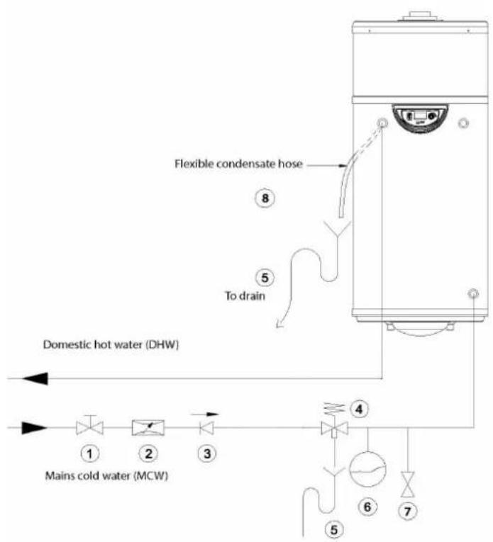
flowchart
graph TD
    A["Domestic hot water (DHW)"] --> B["1"]
    B --> C["2"]
    C --> D["3"]
    D --> E["4"]
    E --> F["5"]
    F --> G["6"]
    G --> H["7"]
    I["Mains cold water (MCW)"] --> J["8"]
    K["To drain"] --> L["5"]
    M["Flexible condensate hose"] --> N["8"]
-
Stop valve*
-
Pressure-reducing valve
-
Check valve
-
Pressure relief valve
5.Drain*
* Components to be provided by the installer
Figure 4: Inlet Connections
6.2.2 Expansion Vessel
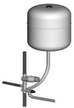
The expansion vessel is mandatory on the Dimplex water heater and can be connected directly to the cold water inlet group, utilising the flexible hose supplied with the vessel. The expansion vessel should always be fitted in accordance with the manufacturer's instructions, see Figure 5. No isolating device should be fitted between the water heater and the cold water inlet group.
Furthermore, it is recommended to mount the vessel higher than the water heater to avoid having to drain the water heater when maintaining and replacing the expansion vessel.
It is important to check the pre-charge pressure of the expansion vessel membrane before filling the cylinder. The pre-charge should be greater than or equal to 3 bar.
natural_image
3D rendering of a cylindrical water pump mounted on a vertical branch with a connecting rod (no text or symbols visible)Figure 5: Connection of the expansion vessel
NOTE: The expansion vessel must be installed to the side of the expansion relief valve on the inlet group. To do this the blanking plug must be removed and the expansion vessel connected, as shown in Figure 5.
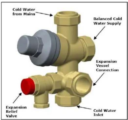
Figure 6: Cold water inlet group
NOTE: The drain valve must be installed lower than the appliance to ensure all of the water is drained away should the immersion heater need to be serviced.
6.2.3 Balanced Cold Water Supply
If balanced cold water supply is required a connection can be taken from the bottom of the inlet group.
6.2.4 Drain Valve
It is also recommended to install a drain valve (not supplied) in the lowest point of the cold water feed to the water heater. This allows the water heater to be drained in a controlled manner should this become necessary.
6.3 Hot Water Outlet
The hot water pipework is to be directly connected to the hot water outlet connection on the water heater.
6.3.1 Thermostatic Mixing Valve
Should a thermostatic mixing valve be required to limit the temperature delivered to the how water taps, a risk assessment for the prevention of Legionella must be carried out. The mixing valve must be installed according to the manufacturers instructions, ensuring none of the safety equipment has been isolated, (i.e. make sure the connection to the thermostatic mixing valve is taken after the safety equipment of the inlet group).
6.3.2 Pipe Insulation
To comply with Part L requirements it is necessary to insulate the hot water pipework from the water heater to the outlets, to reduce the energy requirements for providing hot water. It is also recommended to insulate all other exposed pipework, such as the T&P to the tundish, the coil flow and return and the cold water inlet pipes.
6.4 Discharge Pipes from Safety Devices
6.4.1 Discharge Pipe D1
The temperature and pressure relief valve must be discharged directly or by way of a manifold via a short length of metal pipe (D1) into a tundish; and the discharge pipe must be installed in a continuously downward direction and in a frost free environment. Water may drip from the discharge pipe of the pressure relief device and this pipe must be left open to the atmosphere.
The diameter of discharge pipe (D1) should not be less than the nominal outlet size of the safety device, e.g. temperature relief valve.
Where a manifold is used it should be sized to accept and discharge the total discharge from all the D1 discharge pipes connected to it.
The discharge pipework from the expansion relief valve must be installed constantly falling to an open point of discharge. It is recommended to combine it with the discharge of the temperature and pressure relief valve.
Note: The T&P valve is pre-sealed and if moved the seal will be broken, should this occur, it will need to be resealed with an appropriate sealant (Dimplex part number R00836-1).
6.4.2 Discharge Pipe D2
For a detailed description of the discharge pipework D2 (see Section 5.10.1).
6.4.3 Tundish
The tundish should be vertical, located in the same space as the unvented hot water storage system and be fitted as close as possible to, and lower than, the safety device, with no more than 600mm of pipe between the valve outlet and the tundish (see Figure 2).
Where discharge may not be apparent, e.g. in dwellings occupied by people with impaired vision or mobility, consideration should be given to the installation of a suitable safety device to warn when discharge takes place, e.g. electronically operated.
Note: To comply with the Water Supply (Water Fittings) Regulations, the tundish should incorporate a suitable air gap.

Note: It is important that the tundish is positioned away from any electrical components.
6.5 Immersion Heater
The Edel Air Source Heat Pump Water Heater comes with the immersion heater factory fitted and wired. The immersion heater incorporates an independent non-self resetting over temperature cut-out. Should this operate, please investigate the cause of the cut out before resetting (See Troubleshooting).

The water heater must be filled with water before applying power to the appliance or energizing the element. Failure to do so will damage the element and void any guarantee on the product.
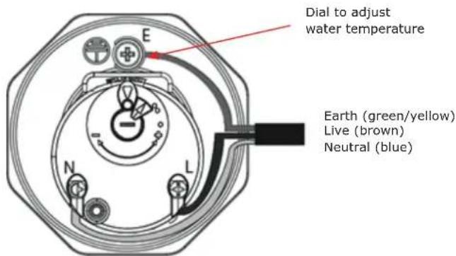
Figure 7: Wiring diagram for Immersion Heater
6.6 Air Connection
The Edel 170 uses a concentric air ducting system (duct-induct) which supplies outside air to the appliances and discharges exhaust air outdoors. The heat pump operates over a large air temperature range (from -7°C to 35°C) using energy from outdoor air to produce domestic hot water. It is essential to correctly design and install the air ducting system to ensure the product operates properly and complies with regulations.
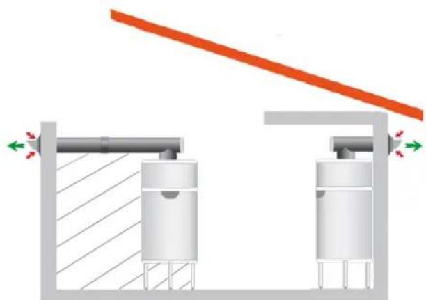
The air supply to and from the Edel heat pump water heater must NOT extract air from the living space of the dwelling. The air must be supplied to the appliance directly from the outside or from another source outside the thermal envelope of the living space.
The ducting used to connect the air intake and exhaust must be sufficiently insulated to prevent condensation forming. Condensation may result in damage to the appliance and/or building fabric.

Dimplex does not take any responsibility for issues caused by poor ducting design or installation.
Figure 9 provides an example of how the ducting inlet and outlet connections should be installed.
natural_image
Pure mechanical diagram showing two cylindrical components connected by a horizontal beam, with directional arrows indicating force or motion (no text or symbols)Figure 9: Examples of air connection to the water

Dimplex does not take responsibility for installation and the operating efficiency of the appliance when installed outside the scope of the guidelines provided in this document.
Failure to use the concentric ducting supplied will prevent the product working properly. Dimplex only recommend using the ducting supplied and maintaining the shortest possible duct runs.
6.7 Ducting Design
It is essential to maintain a minimum air flow rate through the ducting for correct operation of the appliance. The minimum mass flow rate must not drop below 90m3/hr
NOTE: The system reliability and efficiency will be compromised should the mass air flow rate drop below 90m^3/hr .
| Actual Air Flow Rate Maxi mum Pressure Drop | |
| 90 m3/hr 90 Pa | |
| 100 m3/hr 75 Pa | |
| 110 m3/hr 50 Pa | |
| 120 m3/hr 40 Pa | |
During the product specification stage, it is essential that the system designer calculated the required total quantity of ducting connections, lengths, bends and terminations to establish an accurate value for total system pressure drop based on the system air flow rate requirements.
6.7.1 Worked Example
Each ducting component produces a pressure drop that changes with air flow rate. Table 3 illustrates the pressure drop for each ducting component at various system air flow rates.
| Accessories Schema Pressure drop/ typical air flow | ||||
| Concentric air duct∅80/125 | 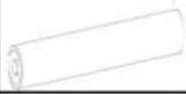 | 90m^3/h | 100m^3/h | 140m^3/h |
| 9 Pa/m | 12 Pa/m | 23 Pa/m | ||
| Accessible Concentric Elbow 90°∅80/125 | 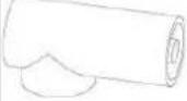 | 90m^3/h | 100m^3/h | 140m^3/h |
| 24 Pa | 30 Pa | 65 Pa | ||
| Elbow 90°∅80/125 | 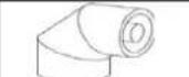 | 90m^3/h | 100m^3/h | 140m^3/h |
| 24 Pa | 30 Pa | 63 Pa | ||
| Elbow 45°∅80/125 | 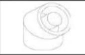 | 90m^3/h | 100m^3/h | 140m^3/h |
| 19 Pa | 23 Pa | 47 Pa | ||
Table 3: Ducting accessories
For a typical installation, the calculation as presented in Table 3 is applicable
| Accessories | Number | ΔP at nominal air flow 140m3/h |
| Extension insulated ø80/125 | 4,5 | 104 Pa |
| Accessible 90° elbow | 1 | 65 Pa |
| Terminal horizontal | 1 | 65 Pa |
| ΔP total | 234 Pa |
| Accessories | Number | ΔP at nominal air flow 90 m3/h |
| Extension insulated ø80/125 | 4,5 | 41 Pa |
| Accessible 90° elbow | 1 | 24 Pa |
| Terminal horizontal | 1 | 25 Pa |
| ΔP total | 90 Pa |
NOTE: The calculated worked example includes all the necessary ducting components to complete the installation and has resulted in a total system pressure drop of 90Pa at 90m3/hr mass air flow rate. This is acceptable as the pressure drop is below the maximum permissible allowed. Only use ducting components that have available pressure drop values.
6.8 Ducting Installation
When installing the air ducting ensure the Edel is situated on the tripod provided and note the correct positions for installing the air connections as illustrated in Figure 9. Dimplex offer a basic vent kit is provided with the product to accommodate installations as per 6.8.1 and 6.8.2. Should it be necessary to install the product further away from the nearest outside wall the vent extension kit is required. The extension vent kit part number is noted on Section 8.7.
NOTE: For installations with longer air duct runs, the total pressure drop must be considered and the ducting components sourced and installed correctly by the installer.
6.8.1 Direct access
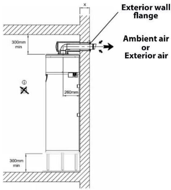
| Rep. | Description |
| a1 | Rear or vertical insulated air duct ∅80/125 - 355mm long(air duct nozzle + ∅125 wall joint + F155/F125 wall flange + ∅125 insulated elbow [useable length 255mm] + ∅80 F/F PVC elbow + cover for insulated elbow) |
| e | ∅80 PVC pipe |
| f | ∅125 PVC pipe |
Figure 10: Direct access installation
DCimplex
- Cut the ∅125 PVC pipe to (X + 25 mm), X is the dimension reference in Figure 10.
- Glue the pipe into the opening in the wall.
- Position the ∅125 wall joint terminal.
- Pass the assembled air duct nozzle through the wall from the outside.
- Direct the air duct nozzle upwards as indicated on the diagram to ensure rain or moisture do not enter the nozzle.
- The ∅125 PVC pipe should overlap by about 25mm on the inside wall.
- Mark the direction of the air duct nozzle on the inside by marking the top of the ∅125 PVC pipe.
- Glue the wall flange onto the ∅125 PVC pipe, and pressing it against the inside wall at the same time.
- Cut the ∅80 PVC pipe to (X + 225mm).
- Remove the cover parts from the insulated elbow (length 355mm).
- Insert the ∅80 PVC elbow into the base of the insulated elbow and affix it to the ∅80 PVC pipe (apply a bit of silicone so that the assembly stays put together).
- Fix the other end of the ∅80 PVC elbow into the air duct nozzle.
- The insulated elbow should be fixed into the wall flange at the same time.
- Slot the ∅80 PVC elbow into the appliance's air outlet, and the insulated elbow into the air inlet.
- Put the cover parts back onto the insulated elbow.
6.8.2 Offset access
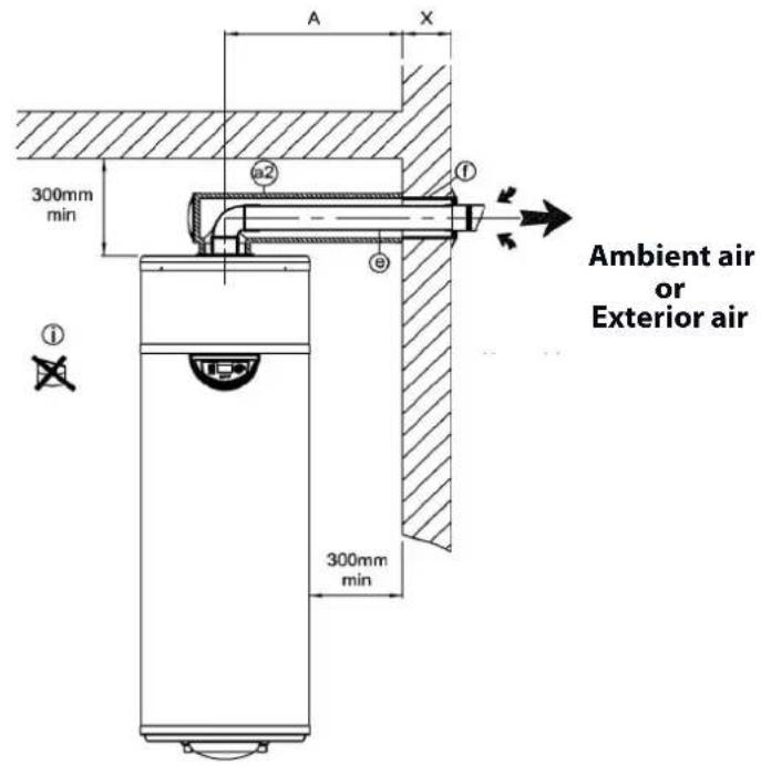
| Rep. | Description |
| a2 | Insulated lateral or vertical ∅80/125 - 975mm air duct(air duct nozzle + ∅125 wall joint + F155/F125 wall flange + ∅125 insulated elbow [useable length 875mm] + ∅80 F/F PVC elbow + cover for insulated elbow) |
| e | ∅80 PVC pipe |
| f | ∅125 PVC pipe |
Figure 11: Offset access installation
- Cut the ∅125 PVC pipe (rep.f) to (X + 25mm).
- Glue it into the air duct nozzle.
- Position the ∅125 wall joint.
- Pass the assembled air duct nozzle through the wall from the outside.
- Direct the air duct nozzle upwards as indicated on the diagram.
- The ∅125PVC pipe should overlap by about 25mm on the inside.
- Mark the direction of the air duct nozzle on the inside by marking the top of the ∅125 pipe.
- Glue the wall flange onto the ∅125 pipe while pressing it against the wall at the same time.
- Cut the ∅80 PVC pipe (rep.e) to (A + X - 30mm).
- Cut the insulated air duct (rep.a2) to (A-205mm).
- Cut the insulated elbow (length 975mm) to (A -5mm).
- Remove the cover parts from the insulated elbow.
- Insert the ∅80 PVC elbow into the base of the insulated elbow and fix it to the ∅80 PVC pipe (apply a bit of silicone so that the assembly stays put together).
- Fix the other end of the ∅80 pipe into the air duct nozzle. The insulated elbow should be fixed into the wall flange at the same time.
- Slot the ∅80 PVC elbow into the appliance's air outlet, and the insulated elbow into the air inlet.
- Replace the cover parts back onto the insulated elbow.
6.8.3 Distanced access
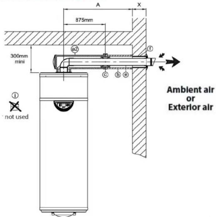
| Rep. | Description |
| a1 | Rear or vertical insulated air duct ∅80/125 - 355mm long(air duct nozzle + ∅125 wall joint + F155/F125 wall flange + ∅125 insulated elbow [useable length 255mm] + ∅80 F/F PVC elbow + cover for insulated elbow) |
| a2 | Insulated lateral or vertical ∅80/125 - 975mm air duct(air duct nozzle + ∅125 wall joint + F155/F125 wall flange + ∅125 insulated elbow [useable length 875mm] + ∅80 F/F PVC elbow + cover for insulated elbow) |
| b | Lateral or vertical ∅int 125, 2.2m long insulated extension |
| c | 1 connecting sleeve for insulated extension pipe |
| e | ∅80 PVC pipe |
| f | ∅125 PVC pipe |
Figure 12: Distanced access installation
- Cut the ∅125 PVC pipe (rep.f) to (X + 25mm).
- Glue it into the air duct nozzle.
- Position the ∅125 wall joint.
- Pass the assembled air duct nozzle through the wall from the outside.
- Direct the air duct nozzle upwards as indicated on the diagram.
- The ∅125PVC pipe should overlap by about 25mm on the inside.
- Mark the direction of the air duct nozzle on the inside by marking the top of the ∅125 pipe.
- Glue the wall flange onto the ∅125 pipe while pressing it against the wall at the same time.
- Cut the ∅80 PVC pipe (rep.e) to (A + X - 30mm).
- Cut the insulated extension pipe (rep.b) to (A-875mm).
- Insert the ∅80 PVC pipe into the insulated extension pipe.
- Fix the insulated extension pipe to the insulated elbow using a connecting sleeve (rep.c).
- Remove the cover parts from the insulated elbow.
- Insert the ∅80 PVC elbow into the base of the insulated elbow and affix it to the ∅80 PVC pipe (apply a bit of silicone so that the assembly stays put together).
- Fix the other end of the ∅80 pipe into the air duct nozzle. The insulated elbow should be fixed into the wall flange at the same time.
- Slot the ∅80 PVC elbow into the appliance's air outlet, and the insulated elbow into the air inlet.
- Replace the cover parts back onto the insulated elbow.
- Place retaiing clamps at intervals of approximately 2 meters on the insulated extension pipe.
NOTE: For distanced access, an extension kit can be supplied by Dimplex, see Section 8.7 This kit provides enough parts to add.
It is possible to source parts from a merchant to make the ducting connections however these must be sufficiently air tight and insulated properly to prevent condensation damaging any adjacent materials in the building.
6.9 Fixing
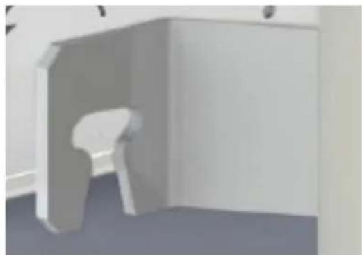
Located at the rear of the appliance, the brackets must be used to fix the appliance to the wall upon completion of the installation.
Upon completion of the ducting installation, the product must be fastened to the adjacent wall to prevent it from toppling over.
natural_image
Exterior view of a modern office building (no signage)Figure 13: Wall fixing
Use the drilling template provided to locate the fixing positions
6.10 Draining the Condensate
The condensates tube should not be directly connected to a drain. It must terminate into open air through a U-bend which has been added and contains water.
- Do not use an elbow on the flexible hose

Figure 14: Detailing the correct connection of condensate draining
6.11 Electrical Connections
The power supply should comply with the regulations in the country of installation, as well as the IEE Wiring Regulations.
A means of disconnection which ensures an electrical isolation in Category III conditions should be installed in fixed cabling in compliance with the installation rules.
Protect the appliance with :
- A 13A fused spur or isolator must be installed adjacent to the appliance for mains supply connection.
-A 16A RCBO type C circuit breaker must be fitted the local consumer unit on the same supply.
If the power supply cable is damaged it must be replaced by a suitably qualified technician or electrician.
6.11.1 Accessing Electrical Connections
To access electrical connections:
- Isolate the electrical connections.
- Remove the cover from the top of the appliance by taking out the screws which fix the lid onto the lower base of the heater.
- Remove the black protective cover from the electronic board.

Only a voltage-free, external connection may be used, or the electronics board may be destroyed.
6.11.2 Electricity Provider Contact
To stop the electrical back-up immersion running during peak time, connect the voltage-free contact from your electricity meter to terminal n°1, please refer to Figure 15.
- Contact open = electrical back-up not authorised to run
- Contact closed = electrical back-up authorised to run
If you choose load shedding level 1, the electrical back-up is prevented from running. If you choose load shedding level 0, both the electrical back-up and the heat pump will be prevented from running (see Section 7.11.6).
To prevent electrical backup operating during peak hours, if a volt free output is not available from the meter, a timer switch should be used if:
- Switch off = backup not allowed
- Switch on = backup allowed
Only a zero-voltage, external control such as a timer switch should be used (if not, the electronic board could be destroyed).
- Pass a 0.75mm 2-wire cable with crimped ends through a cable gland at the back of the appliance and bring the end of the cable round to the electronic board. The other end of the cable should be connected to the timer switch.
- Insert the 2-wire cable through a grommet on the electronics board.
- Connect the 2-wire cable to "Entrée 1" indicated on the electronic board, having removed the existing red bridge beforehand.
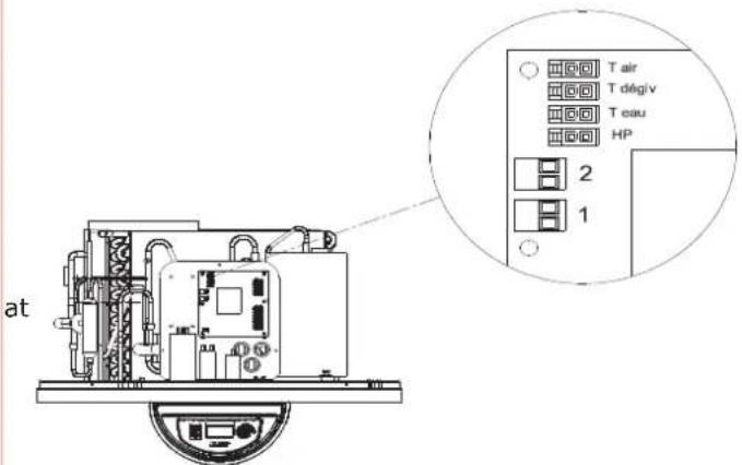
Figure 15: Detailing the electricity provider contact on the electronic board
6.11.3 Connecting the PV Function
This function enables the appliance to operate in auto-production mode, which means that it will use the energy produced by the PV function to supply the heat pump as well as the electrical back-up, in order to heat the water in the tank.
The connection is made between the PV Inverter and connectors 1 and 2 on the electronics board.
- Remove the appliance lid.
- Remove the black cover from the electronic board.
- Connect the PV function cable to connector 1 on the electronic board.
- If the PV function regulator has two control contacts, connect them to Entrée 1 and 2 on the electronic board (see Figure 16).
- Terminal 1: a low level of electrical energy is produced by the PV function.
- Terminal 2: a high level of electrical energy is produced by the PV function.
7 Set-Up and Operation
7.1 Commissioning
Deterioration risk: The water tank must be filled before the appliance is switched on or connected to a power supply.
At the time of commissioning, complete all relevant sections of the Benchmark Checklist located on the inside back pages of this document.
The following commissioning procedures only detail the required steps to be taken for the potable water loop.
1) Before making any mains connections to the inlet control group, flush the mains pipework out to ensure all debris has been removed so as not to damage the strainer within the inlet group.
2) Make final mains connection on combination valve and check all connections and joints. ensure they have been tightened and secured correctly.
3) Before turning on the mains supply to the water heater a hot water tap should be opened, preferably on the same floor or the floor below where the water heater is located.
4) Check the pre-charge in the expansion vessel and ensure it is at least 3 bar. Note actual pressure on label on expansion vessel.
5) Turn on the supply to the water heater and fill until water runs from the open hot water tap. Continue to flush the system until all debris has been removed.
6) Close the hot water tap.
7) Check all joints for leaks, even those not having been altered especially when replacing a vented water heater.
8) Open temperature and pressure relief valve to ensure proper discharge and check after closing that valve is not dripping.
9) Open expansion relief valve to ensure proper discharge and check after closing that valve is not dripping.
10) Check all shower outlets, toilet cisterns and other draw off points for leaks or dripping (especially when replacing a vented unit). Open all water outlets to purge air from pipework and ensure proper operation.
11) Instruct user in the operation of the unit and hand over this manual advising the owner of annual service requirements.
12) Complete the technical data label on the water heater with legible and permanent writing.
13) Please register the appliance on our website www.dimplex.co.uk/register
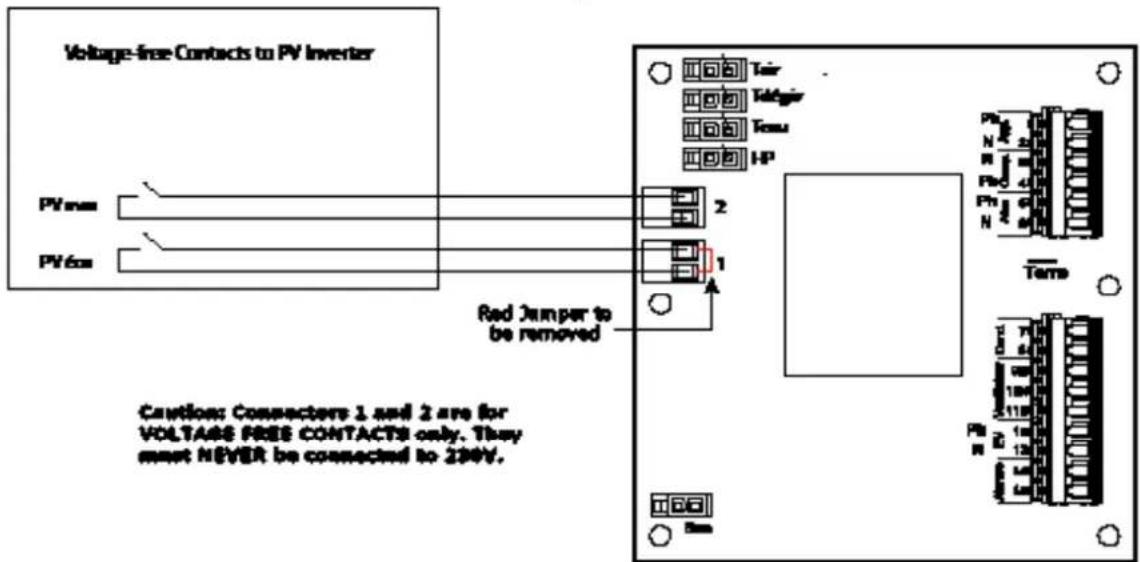
Figure 16: Diagram showing PV connections
7.2 Using your Hot Water Heat Pump
The hot water heat pump mainly operates with the heat pump, as long as the air intake temperature remains in the authorised - 7°C to + 35°C range. Outside of this range, electrical backup ensures that the domestic hot water is heated.
The domestic hot water temperature provided by the heat pump is adjustable up to 60^ C. In case of high domestic hot water consumption, the domestic hot water heater has a comfort function which increases the heating capacity when there is less than 1/3 of the tank's volume left at over 38^ C (see Section 7.11.5). There is also a setting (see section 7.11.7) to activate electrical backup if the heating time is too long.
If more domestic hot water is required from time to time, the heat pump water heater has a "Boost" function (activated by the user) which ensures that the water heats to the desired temperature (for example: 50°C) quickly with the help of the heat pump and electrical backup. This function is deactivated as soon as the required temperature is reached.
From time to time, check that there are no alerts (in case of an alert, please refer to Section 8.6).
7.3 Control Box
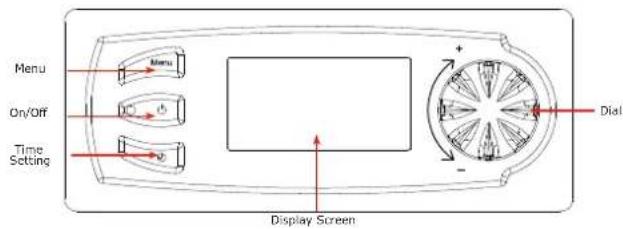

Compressor Activated

Domestic Hot Water Request

Fan Activated

Economy Mode Activated

De-icing in Progress

Freeze Protect Mode Activated

Electrical Backup Activated

Holiday Mode Activated
7.4 Setting the Language
The language must be selected when the appliance is turned on for the first time. Turn the dial to the left, select 'English' and press the dial to confirm. The language menu can be accessed at any time.
- Press 'Menu'.
- Turn the dial to scroll through the menu options:
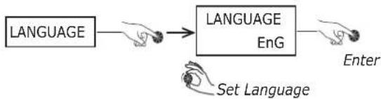
flowchart
graph LR
    A["LANGUAGE"] --> B["ENG"]
    B --> C["Enter"]
    D["Set Language"] --> B
- Press 'Menu' to return to the main screen.
7.5 Setting the Time
- Press 'Clock':
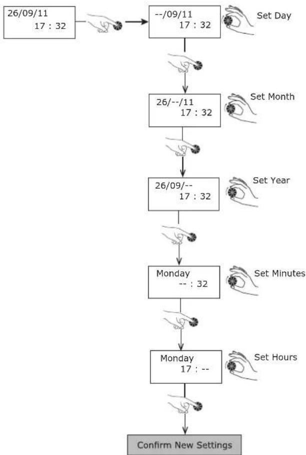
flowchart
graph TD
    A["26/09/11\n17:32"] --> B["--/09/11\n17:32"]
    B --> C["26/--/11\n17:32"]
    C --> D["26/09/--\n17:32"]
    D --> E["Monday --:32"]
    E --> F["Monday\n17:--"]
    F --> G["Confirm New Settings"]
- See section 7.11 for instructions to gain access to installer menu
7.6 Setting the Water Temperature
The water temperature can be adjusted between 30^ C and 65^ C. The heat pump alone heats the water up until 60^ C. Beyond this temperature, up to 65^ C, the electrical backup immersion takes over.
- Press 'Menu'.
- Turn the dial to scroll through the menu options:
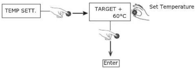
flowchart
graph TD
    A["TEMP SETT."] --> B["TARGET + 60°C"]
    B --> C["Enter"]
    D["Set Temperature"] --> B
- Press 'Menu' to return to the main screen
- In order to get the best from your heat pump, we recommend that you do not leave the set water temperature too high unless necessary. The default temperature is set at 60°C.
7.7 Holiday Mode
'Holiday' mode puts the appliance on standby whilst the freeze protection mode remains active. This function can be programmed to run between 1 and 99 days and is effective as soon as the number of days has been confirmed.
- Press 'Menu'.
- Turn the dial to scroll through the menu options:
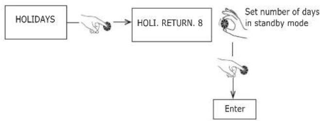
flowchart
graph TD
    A["HOLIDAYS"] --> B["HOLI. RETURN. 8"]
    B --> C["Set number of days in standby mode"]
    C --> D["Enter"]
- Press 'Menu' to return to the main screen.
'HOLIDAY' mode switches off automatically at the same time when the number of days set has ended.
Throughout the holiday period, the heat pump water heater shows 'Holi. Return.' on the display screen, as well as a countdown of the days.
-To cancel holiday mode select 0 days
7.8 BOOST Function (for occasional use)
The 'BOOST' function temporarily uses both the immersion heater and the heat pump to increase the temperature during a heating cycle. The "electrical backup" symbol flashes while it is activated.
- Press 'Menu'.
- Turn the dial to scroll through the menu options:

flowchart
graph LR
    A["BOOST YES"] --> B["Enter"]
- Press 'Menu' to return to the main screen
The 'BOOST' function is automatically deactivated as soon as the set temperature is reached (end if heating cycle). - 'BOOST' can be cancelled by selecting 'no' in the menu
7.9 Electric Mode
(to operate with electrical backup)
Electric mode uses only the immersion heater to heat the water in the heat pump water heater. It provides a back-up option if for any reason the heat pump is not running (ducting not yet connected, dusty renovation work being carried out near the appliance....). This can be turned off if perferred.
- Press 'Menu'.
- Turn the dial to scroll through the menu options:

flowchart
graph LR
    A["ELEC MODE YES"] --> B["Hand icon pointing to node"]
    B --> C["Enter"]
- Press 'Menu' to return to the main screen.
7.10 Programming
Programming enables you to define the periods of time the appliance runs in 'Economy', 'Comfort' or 'Off' mode (freeze protection mode). Electrical backup is not allowed while the appliance is in 'Economy' mode.
To access the program menu:
- Press the 'Clock'.
- Press down for 3 seconds until the screen displays 'Settings'.
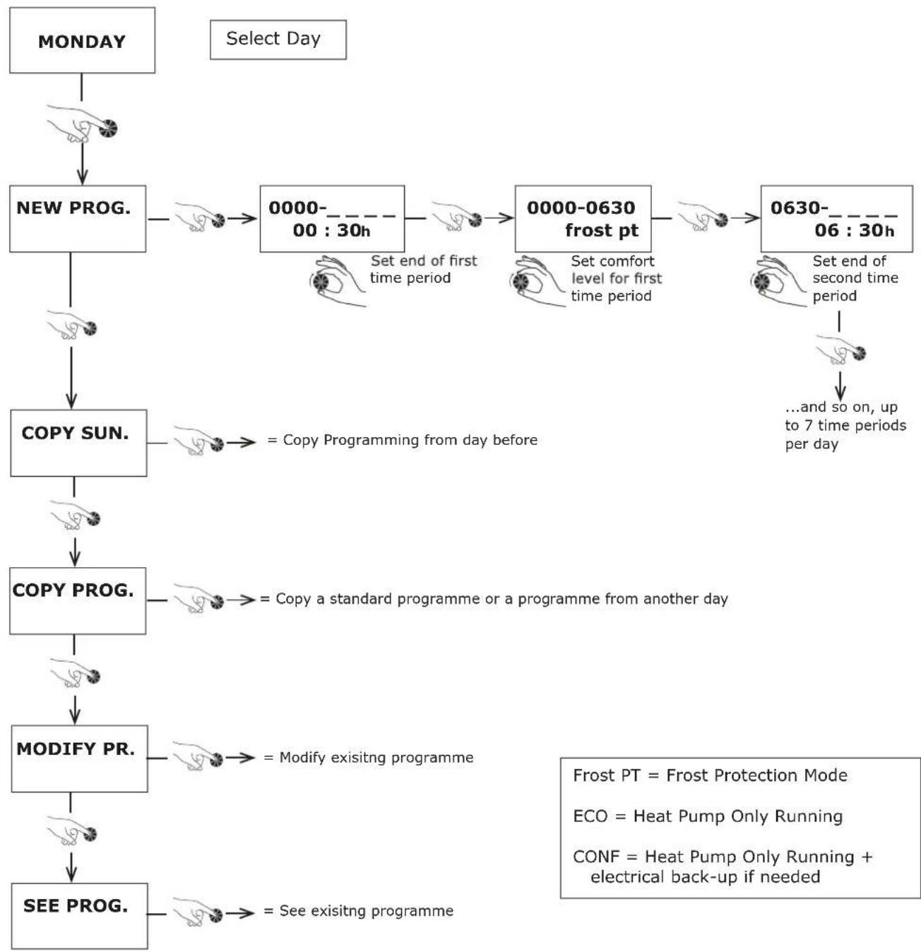
flowchart
graph TD
    A["MONDAY"] --> B["NEW PROG."]
    B --> C["COPY SUN."]
    C --> D["COPY PROG."]
    D --> E["MODIFY PR."]
    E --> F["SEE PROG."]

    subgraph Select Day
        B --> G["0000-00:30h"]
        G --> H["0000-0630 frost pt"]
        H --> I["0630-06:30h"]
        I --> J["...and so on, up to 7 time periods per day"]
    end

    G --> K["Set end of first time period"]
    H --> L["Set comfort level for first time period"]
    I --> M["Set end of second time period"]
    K --> N["Copy Programming from day before"]
    L --> O["Copy a standard programme or a programme from another day"]
    M --> P["Modify existing programme"]
    N --> Q["Frost PT = Frost Protection Mode"]
    O --> R["ECO = Heat Pump Only Running"]
    P --> S["CONF = Heat Pump Only Running + electrical back-up if needed"]
    Q --> T["See existing programme"]
    R --> U["CONF = Heat Pump Only Running + electrical back-up if needed"]

Heating time for the tank varies according to the outdoor temperature.
7.11 Installer Menu
It may be necessary to adjust certain settings to optimise the performance of the heat pump water heater, depending on how the appliance is installed.
Accessing the Installer Menu:
- Press 'Menu'
- Turn the dial until the screen displays 'Inst. Menu'
- Press the 'Clock' and 'Menu' buttons simultaneously
- Keep both buttons pressed down until the screen goes blank
To adjust installation settings
To go back to default settings
To display temperatures of sensors and inlets default settings
To see the meters running, count start-ups etc.
To display locking settings
To display PV settings
7.11.1 PV Mode
| Setting Description Unit Range | Factory setting | |||
| MODE PV | Photovoltaic mode activated | - | yes no | no |
| PRIORITY | Anti-legionellosis cycle time intervals | - | yes no | yes |
- PV mode must be activated in the controller to take account of connections as described in Section 6.11.3. If the PV mode regulator is connected to connectors 1 and 2 on the electronics board.
- The electrical energy which is produced is stored in the form of hot water. The PV function can be set to two different levels of production.
- PV ECO = the lower level of photovoltaic electricity production. The heat pump generates a higher water temperature. The hot water temperature must be somewhere in-between the ordinary hot water temperature and 60°C (factory setting: 60°C).
- PV MAX = the higher level of photovoltaic electricity production. The heat pump and electrical back-up generate a higher water temperature. The hot water temperature must be somewhere in between the eco mode hot water temperature and 65°C (factory setting: 65°C).
- Turn the dial to set the mode:
MENU → INST. MENU → PV MODE
-
Select 'Yes'.
-
Press the dial to confirm.
-
Press the 'Menu' key.
-
Set the desired domestic hot water temperature.
-
Turn the dial to select the primary function:
MENU→ INST. MENU→ PV MODE→ PRIORITY
Yes: the signals from connectors 1 and 2 take precedence over eco, holiday and frost protection modes.
No: frost protection and eco modes take precedence over the signals from connectors 1 and 2.
N.B:
If PV mode is chosen as the primary function, the domestic hot water will also be heated during non-selected time periods, e.g. in holiday mode and outside of the programmed time slots. If you only wish the domestic hot water to be heated during authorised time slots, adjust the setting to "No".
- Press the dial to confirm.
- The load shedding function will not be available.
7.11.2 Adjusting the Operating Settings
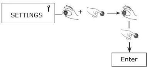
flowchart
graph TD
    A["SETTINGS"] --> B["+"]
    B --> C["Process"]
    C --> D["Enter"]
| Setting | Description Unit Options | Factory Setting | ||
| ANTI-BACT. | Time interval for anti-legionella cycle | Days | No - 99 | No |
| FAN MODE | Ventilation mode | - | 1, 2 or 3 | 1 |
| T°C MINI | Min. temp. for electrical backup | - | No or 43°C | No |
| SHEDDING | Load shedding level | - | 0, 1 or 2 | 1 |
| MAX. TIME | Max. heating time | Hours | No, auto 1 to 24 | No |
Table 4: Settings
- Press 'Menu' twice to return to the main screen.
7.11.3 Anti-Bacteria (Anti-Bact)
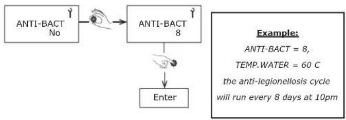
flowchart
graph TD
    A["ANTI-BACT No"] --> B["Anti-BACT 8"]
    B --> C["Enter"]
- Press 'Menu' twice to return to the main screen.
Factory Setting = No
- No legionella cycle except the return from vacation and during exit frost over 3 days.
- During the legionella cycle the water temperature is raised to 60°C by the heat pump.
- If the hot water is already set to 60^ C (See Section 7.6) then legionella cycle will not run as temperature is already obtained.
- If a cycle is interrupted by loss of electrical power then the cycle will run at the next cycle period.
- The frequency of day can be adjusted according to number of days
-During the anti-legionellosis cycle the temperature is raised between 55°C and 70°C
7.11.4 Fan Mode
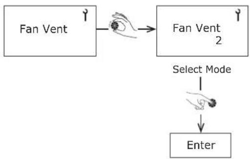
flowchart
graph TD
    A["Fan Vent"] --> B["Select Mode"]
    B --> C["Enter"]
- Press 'Menu' twice to return to the main screen.
Factory Setting = 1
- Mode 1 = Standard mode, automatic ventilation.
- Mode 2 = Manual mode, forced ventilation.
- Mode 3* = Ventilation during the heating of the water and ventilation controlled by thermostat. Thermostat is connected to input of the electronic card in the heat pump water heater (see wiring diagram).
* In the case of activation of the PV mode, controlled ventilation (Mode 3) is not available.
* The electric back-up immersion heater will activate until the water temperature reaches 43°C. The heat pump will complete the remaining charge to set temperature.
7.11.5 Minimum Temperature
It is possible to allow the operation of the immersion heater along with the heat pump to prevent the water temperature falling below a minimum comfort temperature of 38^ C. The immersion will then heat the water to 43^ C, once this temperature has been reached the immersion will stop and the heat pump will finish the complete heating of the water heater.
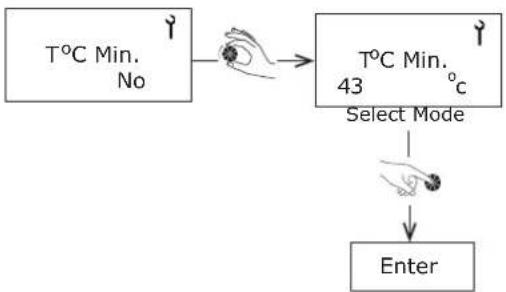
flowchart
graph TD
    A["T°C Min.<br>No"] --> B["Select Mode"]
    B --> C["Enter"]
- Press 'Menu' to return to the main screen.
- By default this is not active.
- In case of load shedding, the function <T^OC Mini> is not active.
7.11.6 Shedding
You can select which items are restricted from running during load shedding (immersion heater or heat pump).
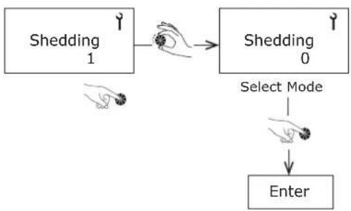
flowchart
graph TD
    A["Shedding 1"] --> B["Shedding 0"]
    B --> C["Enter"]
    D["Shedding 0"] -->|Select Mode| E["Shedding 1"]
- Press 'Menu' to return to the main screen.
If the power contact is open:
- Mode 0 = Nothing is allowed to run.
- Mode 1 = Only the heat pump will operate.
- Mode 2 = Heat pump and boost are will operate (neutralising the peak hours).
If the PV function is activated then the load shedding from the voltage-free contact (Entrée 1/2) is not possible. In this case it is necessary to go through the programme scheduling (See Section 7.10).
7.11.7 Maximum Time
A period of time can be chosen where the electrical back-up will run at the same time as the heat pump to speed up the heating of the water in the tank. If you choose Max. Time= AUTO, the heating time is limited to 5 hours maximum.
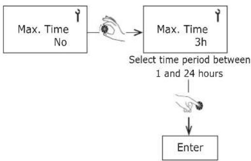
flowchart
graph TD
    A["Max. Time\nNo"] --> B["Select time period between\n1 and 24 hours"]
    B --> C["Enter"]
- This function is deactivated by default.
- Press 'Menu' to return to the main screen.
7.11.8 Locking the Keyboard
Permanent and automatic locking
The "Locking" option enables you to create two possible levels of locking for accessing the menus. In the "Installer" menu, turn the dial to "Locking".
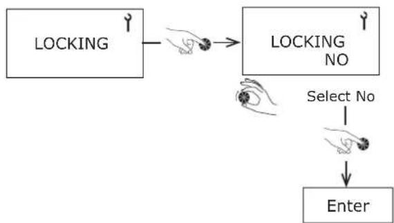
flowchart
graph TD
    A["LOCKING"] --> B["NO"]
    B --> C["Select No"]
    C --> D["Enter"]
NO = Locking is not activated but manual locking is possible by pressing 'Menu' for 3 seconds.
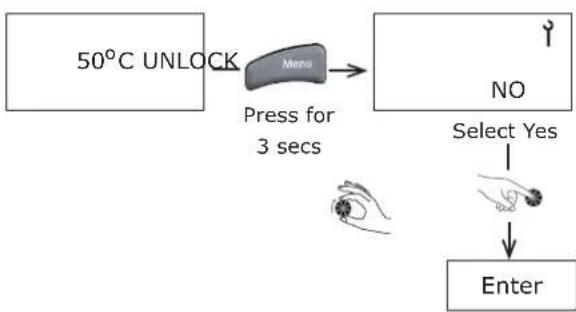
flowchart
graph TD
    A["50°C UNLOCK"] --> B["Menu"]
    B --> C["Press for 3 secs"]
    C --> D["Select Yes"]
    D --> E["Enter"]
AUTO = To lock menu access with temporary unlocking (60) sec, press 'Menu' for 3 seconds.
Manual Locking from the Main Screen
Without gaining access through the 'installer' menu and provided that locking settings are not already in place.
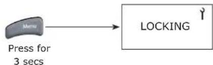
flowchart
graph LR
    A["Menu"] --> B["LOCKING"]
    style A fill:#f9f,stroke:#333
    style B fill:#ccf,stroke:#333
- Press 'Menu' to return to the main screen.
7.11.9 Resetting Parameters
Resetting the parameters enables you to go back to the default settings. Go to the 'Installer' Menu and turn the dial to 'Reset'.
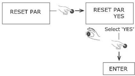
flowchart
graph TD
    A["RESET PAR"] --> B["Select 'YES'"]
    B --> C["ENTER"]
7.11.10 Reading Display
The 'Read Data' menu shows you, in real time, the information given by sensors. To access hold the dial for 3 seconds until 'Display' menu shows, turn the dial to select the desired display.
| Display | Description | Reference on electronics board |
| WATER | Domestic hot water temperature in lower part of tank | Teau |
| AIR | Temperature of heat pump air intake | Tair |
| EVAP. | Temperature of heat pump evaporator (expansion valve outlet) | Tdégiv. |
| CLOCK SWITCH | Off-peak hours switch(0 = on; 1 =off) | heures creuses |
| FAN CONTR. | Fan control switch(0 =on; 1 =off) | hygrostat |
| PV ECO | Contact input 10 = open 1 = closed | 1 |
| PV MAX | Contact input 20 = open 1 = closed | 2 |
The temperature which is permanently displayed on the screen is the set temperature and does not necessarily indicate the temperature of the water immediately available in the tank.
7.11.11 Counters (Meters)
The 'Counters' menu shows the number of start-ups from the heat pump and the electrical backup. In the 'Installer' menu, turn the dial to 'Counters'.
Counter No.1: Number of start-ups from the heat pump.
Counter No. 2: Number of start-ups from the electrical backup.
Counter No. 3: Cumulated heated pump running time.
8 Maintenance
The maintenance of this appliance covers the critical areas of the Domestic Hot Water Cylinder, the Heat Pump Module, Air Connections and Electrical Connections.

All maintenance on this product must be undertaken with F Gas certification as required.

In order to maintain efficiency and improve durability it is advised that an annual maintenance check should be carried out by a qualified professional.

Failure to service this appliance annually may invalidate the warranty.
- Switch off the heat pump water heater before opening it.
- Wait for the fan to come to a complete stop before starting work on the appliance.
- Do not get any water on any of the electrical components.
- The pressure-limiting device should be activated regularly to eliminate limescale and to check for blockages.

The R290 refrigerant in the heat pump circuit poses no risk to the environment, but it is flammable.
• The R290 refrigerant is odourless.
- Do not damage the pipes in the refrigerant circuit.
- Do not handle a flame or any other flammable source on the inside of the appliance.
- If the refrigerant is leaking, unplug the appliance, air out the room, and contact customer service.
- Do not use any mechanical means to speed up the defrosting process.
- Do not pierce or burn the appliance: in case of intervention on the refrigerant circuit, the refrigerant must be recovered.

The refrigerant circuit containing flammable refrigerant complies with all national gas regulations.
- In case of maintenance of the refrigerant circuit:
1) Secure the area you will be working in,
2) Inform people of the potential danger involved in the work.
3) Ensure that the risk of inflammation is minimised.
4) Avoid working in a confined space; the area must be sufficiently ventilated.
5) Check the area with an appropriate leak detector before and during the work.
6) Place a CO₂ dry powder extinguisher near the work area.
8.1 DHW Cylinder
After servicing, complete the relevant Service Record section of the Benchmark Checklist located on the inside back pages of this document. To meet with warranty requirements, the cylinder must be serviced annually.

When draining the tank, ensure that there is a large enough air inlet at the top to avoid any depression in the tank; failure to do so will invalidate the warranty.
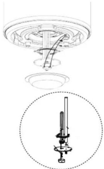
Periodically the immersion heater should be removed cleaned and the unit flushed out. If the system is drained for internal inspection Check the O-ring seal for damage and replace if necessary. A torque of 40 Nm is recommended when tightening up the immersion after it has been removed and refitted as per Figure 17
natural_image
Technical diagram of a mechanical assembly with a circular inset showing a cylindrical component (no text or symbols)Figure 17: Immersion heater cleaning
- Draw some water from cold water tap and retain in container.
- Isolate cold water mains supply from cylinder.
- Briefly open temperature and pressure relief valve to assure safe discharge and check that valve is not dripping when closed.
- Briefly open the expansion relief valve to assure safe discharge and check that valve is not dripping when closed. The expansion relief valve should be operated regularly to remove lime deposits and to verify that it is not blocked.
- Open hot water tap and release remaining pressure from unit.
- If the system is drained completely for an internal inspection, ensure the hot water tap remains open, connect a hose to the drain valve and ensure a safe discharge.
- Note the set pressure of the pressure reducing valve. Remove cartridge and clean strainer in water provided in container. Re-assemble pressure reducing valve ensuring the correct pressure is set.
- Periodically the immersion heater should be removed cleaned and the unit flushed out. If the system is drained for internal inspection Check the O-ring seal for damage and replace if necessary. A torque of 40 Nm is recommended when tightening up the immersion after it has been removed and refitted.
- Check electrical wiring connections and the condition of the cable of the immersion heater and the thermostat.
- The immersion heater boss can also be used for access to view the internal components of the cylinder.
- Re-commission unit (see chapter 7.1).
8.2 Heat Pump

Any work on the refrigerant circuit must be carried out by a qualified professional with an F Gas Category 1 certificate of aptitude.

It is strictly prohibited to release refrigerant into the atmosphere. The refrigerant must be collected before any work is carried out on the circuit.
- Remove insulation from ducting as well as the ducting itself and thus remove the hood from the unit as per figure 18 to expose the compressor, heat exchanger etc.
- Check the compressor for ice formation.
- Check the circuit for leak-tightness by carrying out a test of the refrigeration components with an appropriate R290 sniffer.
- Check whether the components of the refrigerant circuit show any signs of rust or traces of oil.
- Check the unit's components for wear or defective items.
- Inspect for build-up of debris in ducting and hood, remove if necessary.
- The heat exchanger should be examined for dirt and dust and cleaned with warm water carefully to avoid damaging the fins. Make sure that the air can circulate between the fins and around the product.
- Check that the cables are securely seated on the connection terminals.
- Check that the fan runs freely.
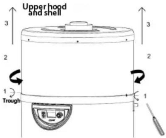
Figure 18: Hood removal
8.3 Air intake & Exhaust
- Both the exhaust and air intake vents must be inspected and cleared of any debris stuck in the vents.
- Ensure the evaporator is checked at least once a year, more depending on the cleanliness of the air
8.4 Heat Pump Condensation
-
To check that condensation is draining correctly:
-
Remove upper cover (see Figure 15).
- Check for blockages in the drainage hole.
- Clean the condensate recovery container, where deposits from air intake may have gathered.
-
Clean the flexible draining hose.
-
The pressure limiting device must be switched on regularly to eliminate limescale and check for blockages.
- Check that all hydraulic connections on the heat pump water heater are watertight.
- The condensate drain should be inspected to ensure the red plug has been removed and unrestricted draining of condensation is allowed.
8.5 Electrical Connections
Incorrectly made electrical connections can result in over-heating and hence a fire risk. When installing or servicing the product, please ensure the wiring is adequate to minimise risk of overheating. Please ensure you have:
- Remove the dust from power supply connections.
- Used the correct type and cross-sectional area cable to meet manufacturer and Wiring Regulation requirements.
- When stripping the insulation from the individual conductors, taken care to not damage the strands of the conductor wire, which would reduce the cross-sectional area of the conductor.
- Ensured the conductors are tightly and securely connected to the controls or immersion heater
- Ensured the bared conductors are correctly inserted into the terminals, to avoid bearing on the insulation sleeving or only partially clamping the conductors.
- Securely anchored the supply cable using the means provided to avoid exerting any external strain to the cable and hence to the terminals.
- Checked to ensure the product is earthed correctly; the Live and Neutral connections are to the correct terminals, and the Residual Current Device (RCD) operates correctly.
- Regularly checked the electrical connections as part of the maintenance schedule, to ensure the wires remain in good condition and terminations remain secure. Ensure any spare parts used during maintenance of the product are an authorised spare part and meet the manufacturers' requirements.
Waste electrical product should not be disposed of with household waste. Please recycle where facilities exist. Check with your Local Authority or retailer for recycling advice.
8.6 Troubleshooting
| Issue Check | |
| The Heat Pump is not working | - That the desired water temperature is higher than the temperature of the water in the tank.- There is power supply to the appliance.- The green light is on.- That the appliance is not in holiday mode (see Section 7.7)- That the air intake or ambient temperature is under - 7°C or over +35°C.- That the timer has not been programmed to stop the appliance operating ('Economy' light will be on (see Section 7.3).- If an error message is displayed on the screen (see Section 8.8). |
| No Hot Water - That the volume consumed is not higher than the volume in the tank.- The time period the appliance operates is not too short (12hrs minimum if connected to piping).- The water temperature is not set too low. | |
| Condensates are not draining | - The draining system for dirt or blockages: Remove the cover (see Figure 18) and check the opening.- That tubes do not have bends or "U" shapes that can collect water.- That the end of the tube is not blocked off and has access to open air. |
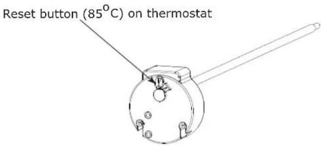
| Electrical backup is not working | - That your electricity provider or your timer is not preventing the appliance from functioning, 'Economy' symbol should be on (see Section 7.7).- A heat-limiting safety thermostat for electrical backup has not been activated after over-heating (>85°C). If this is the case, reset it.- Before resetting, check:• that the heating element does not have limescale.• clean or replace if necessary. |
Table 5: Troubleshooting
Do not adjust the settings on the thermostat.
| Description Image Part No Description Image Part No | |||||
| 22mm x 3bar Inlet con- trol group |  | X-R00041-1 Sensor Ig 460 X-B124 | 45 |  | |
| Inlet control group PRV cartridge | [XH3Z] | X-R00009-1 Sensor Ig 1200 X-B12 | 44575 |  | |
| 18 litre expansion vessel | X-R00045-2 Defrosting sens kit X-B4993072 |  | |||
 | |||||
| Expansion vessel fixing kit |  | X-R00094-2 RF module 500000710 | [4YBH] | ||
 | |||||
| DN16 3/4" BSP x 1000 flex pipe |  | X-R00095-1 Fan 140 500001242 | 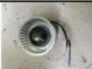 | ||
| 1/2" BSP T&P valve X-R00032-1-5-1-1-1-1-1-1-1-1-1-1-1-1-1-1-1-1-1-1-1-1-1-1-1-1-1-1-1-1-1-1-1-1-1-1-1-1-1-1-1-1-1-1-1-1-1-1-1-1-1-1- | |||||
 | sure 500001270 | [T40Z] | |||
| 15 x 22 straight PE tundish | [WZ3Z] | X-R00047-1 Insulated hood | [ATZW] | 500001243 | |
| Temp. sensor - 25°C - |  | X-B1243950 | Electrical lid |  | X-B4992027 |
| C3S PCB Controller | [0MHY] | X-B1244096 | Heating cover ele- ment | [ZXW] | 500001244 |
| 70-85°C Thermostat |  | X-1239160 | Condensate T pipe |  | 500001245 |
| 1200W electric heating element |  | X-1244562 | EDL170 Vent Kit | [S800] | 500001044 |
| Electric heating seal | [2YGZ] | X-1657452 | EDL170 Extension Vent Kit |  | 500001493 |
| PCB +Display +PGM +Cable | 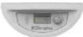 | X-4592570 | |||
| Display Screen Dial |  | X-1758866 | |||
| Thread sealant |  | X-R00836-1 | |||
Table 6: Edel Air Source Water Heater Spare Part
8.8 Error Message Codes: Errors, Solutions and Operating in case of Error
N.B Errors can be dismissed by briefly pressing the dial (manual reset).
| Display Error Probable causes Solutions | Temporary operation measures while waiting for problem to be solved | |||
| MEMO/ BUS | Electronic board defect. Bus wire defect. Display screen defect. | Voltage too high on electrical network.Cabling error during electrical connection (connection to electricity provider or moisture sensor...).Damage during transportation. | Replace main electronics board or;Replace display screen board. | Appliance non-functional. |
| T_AIR | Air temperature sensor defect (Temperature of air taken in). | Sensor not functioning.Sensor unplugged from board.Sensor cable damaged. | Replace sensor. | Heat pump non-functional.Electrical backup heats water to 43°C (min 38°C). |
| T_DE-FROST | Evaporator sensor defect (de-icing temperature). | Sensor not functioning.Sensor unplugged from board.Sensor cable damaged. | Replace sensor. | Heat pump non-functional.Electrical backup heats water to 43°C (min 38°C). |
| T_water | Tank water sensor defect. | Sensor not functioning.Sensor unplugged from board.Sensor cable damaged. | Replace sensor. | Heat pump non-functional. |
| ClockClock/timer defect. | Voltage too high on electrical network.Damage during transportation. | 1-Press «clock settings» and set date and time.2-If the error message still does not disappear, replace the electronics board. | Programmed heating periods are no longer valid: the water is maintained continuously at the standard set temperature (if no signal or control is connected to the «external control» switch). | |
| OVER PRESS. | Heat pump pressure too high. | No water in tank.Water is too hot (>75°C)Water sensor removed from tank.Defective water sensor. | Check that the tank has been properly filled with water and purged of air.Change the water sensorCheck that the water sensor is in the right position in the tank. | Heat pump is non-functional.Resets automatically.Authorised to run on backup. |
| FREQ. DEFRO | De-icing too often. | Insufficient airflow.Air inlet / outlet blocked.Ventilation duct blocked.Air duct is too long or has too many elbows.Evaporator clogged. | Check that air is circulating properly throughout the piping circuit.Check pipe lengths.Check any filters on air ducts.Check evaporator is clean. | Heat pump non-functional.Electrical backup heats water to 43°C (min 38°C). |
| LOW PRES | Heat pump pressure too low. | Insufficient airflow.Air inlet / outlet blocked.Ventilation duct blocked.Fan blocked or out of order.Evaporator clogged.Ice on evaporator. | Check the fan is working.Check that air is circulating properly throughout the piping circuit.Check pipe lengthsCheck any filters on air ducts.Check evaporator is clean. | Heat pump non-functional.Electrical backup heats water to 43°C (min 38°C). |
| OVER-HEAT | Domestic hot water overheat (water temperature >85°C) | Defective water sensorWater sensor removed from tank | Check that sensor is in the right position in the tank | Heat pump is non-functionalResets automatically |
| ERR 01 | Incorrect temperature sensor reading. | The air and de-icing sensors are the wrong way round on the electronics board.The de-icing sensor and water sensors are the wrong way round on the electronics boar.The de-icing sensor is connected to the air input, the air sensor is connected to the water input, the water sensor is connected to the de-icing input. | Reposition the temperature sensors correctly on the main electronics board. | Heat pump non-functional. |
| Incorrect reading from the de-icing sensor. | The de-icing sensor is not properly connected to the tube and is measuring air. | Reposition the de-icing sensor properly in the tube. | ||
| The heat pump has run out of gas. | There is a leak on the refrigerant circuit. | Find and repair the leak before filling the refrigerant circuit. | ||
| The expansion valve is not working. | The expansion valve is damaged or broken due to work being carried out on the appliance or it being in contact with a part which vibrates. | Replace expansion valve. | ||
| The compressor is not working and safety temperature is activated. | Weakness in compressor. | Replace compressor. | ||
| ERR 02 | Incorrect temperature sensor readings. | The air and water sensors are the wrong way round on the electronics board.The de-icing sensor is connected to the air input, the air sensor is connected to the water input, the water sensor is connected to the de-icing input. | Reposition the temperature sensors correctly on the main electronics board. | Appliance non-functional. |
| ERR 03 | Incorrect temperature sensor readings. | The de-icing sensor is connected to the air input, the air sensor is connected to the water input, the water sensor is connected to the de-icing input. | Reposition the temperature sensors correctly on the main electronics board. | Appliance non-functional. |
| ERR 04 | Incorrect de-icing and water sensor readings. | The de-icing sensor and the water sensor are the wrong way round on the electronics board. | Reposition the temperature sensors correctly on the main electronics board. | Heat pump non-functional. |
| ERR 08 | Wrong measure on de-icing sensor. | De-icing sensor is defective. | Replace de-icing sensor. | Product runs in alternative mode with heat pump. |
| ALARM EPRO | The display screen electronics board has a memory problem. | The display screen electronics board is damaged. | Replace display screen electronics board. | Appliance non-functional. |
* DHW = Domestic Hot Water
Table 7: Errors
9 Control App
9.1 Home Screen
- Select mode that the Edel is operating in.
• Use boost function for immediate hot water.
• Overview of the cylinder charge and available hot water.
• To access more settings
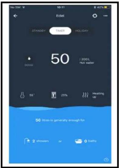
9.2 Holiday Mode
- Ensure the cylinder doesn't charge when away, and that there will be hot water upon your return.
- Select a date in the future when the Holiday period will conclude.
- Turn cylinder back into Timer mode at any point by pressing "TURN ON NOW".
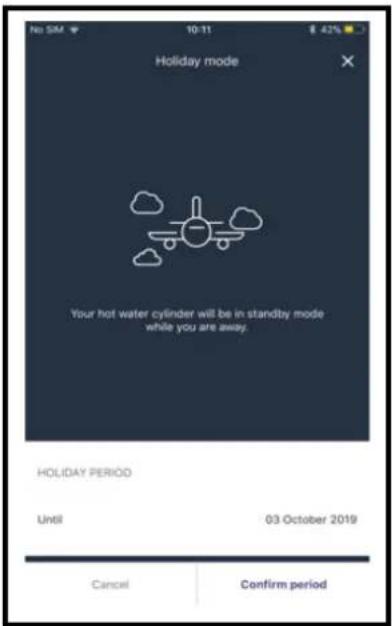
9.3 Schedule Control
• Create individual schedules for each day to suit the customer.
• Copy a schedule to any day of the week.
- Allows control over your appliance to ensure that you always have hot water and are not unnecessarily using energy.
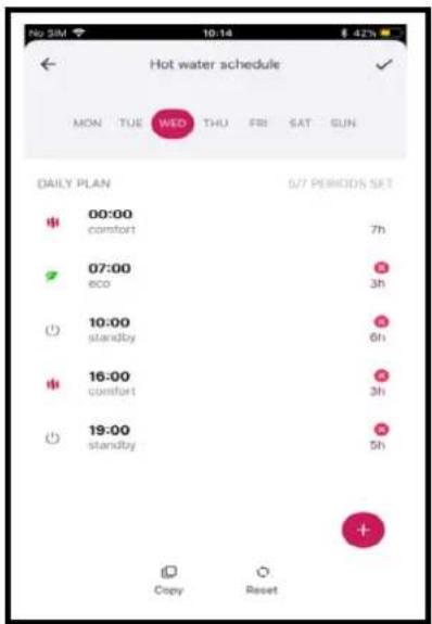
9.4 Hygiene Mode
- Select to run hygiene mode on the app, and define the frequency of hygiene mode up to 99 days.
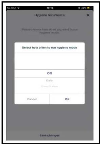
10 Warranty
The tank is guaranteed against breakage for a period of five years, starting from the date of purchase. The appliance must be registered with Dimplex and can be done so quickly online by visiting www.dimplex.co.uk/register. In the absence of registration documentation, the date of manufacture will be used to determine the start date. If the tank is broken, the whole appliance will be replaced.
The other parts are guaranteed for a two year period starting from the date the appliance was activated, if the warranty voucher was sent back to the manufacturer. In the absence of this document, the date of manufacture will be used to determine the start date.
The appliance is guaranteed against all manufacturing defects, provided that it was installed by a qualified professional using our instruction manuals. A defective part does not warrant the whole appliance being replaced.
The warranty only extends to parts which we identify as having been defective at manufacture. If necessary, the part or product should be returned to the manufacturer but only with prior agreement from our technical department. Labour, transport and packaging costs are the responsibility of the user. Repairs on a device will not result in compensation. The parts warranty ends at the same time as the appliance warranty.
The warranty only applies to the appliance and its components and excludes any part or installation external to the appliance. Regular maintenance of the appliance by a trained professional is essential for ensuring sustained use and durability. In the absence of regular maintenance, the warranty will not apply. If an appliance is presumed to have been the cause of any damage, the appliance and the damage must be left as they are and not tampered with.
10.1 Warranty Limits
10.1.1 Exclusion from Warranty
10.1.1.1 Use
Cases where warranty (unlimited) is void :
- Water supply being other than cold domestic water, (such as excessive water hardness), or which has particularly hostile or abnormal properties which do not comply with the national rules and current standards.
- The appliance being switched on before it is filled.
10.1.1.2 Handling
Cases (unlimited) where warranty is void:
- Any damage sustained by impacts or falls during handling after delivery from the factory.
- Deterioration in the condition of the appliance after handling where the instructions in the manual have not been followed.
- Damage occurring in the appliance when it has been switched on less than an hour after it has been leaning to the side or laid flat.
10.1.1.3 Installation Site
Cases (unlimited) where the warranty is void:
- Placing the appliance where it can be subject to ice or other bad weather conditions.
- Non-compliance with the instructions in the manual when installing the appliance.
- Installing the appliance on a surface which cannot bear its weight when it contains water.
- Installing the appliance in a room with surface area of less than 20m^2 where there is no piping for air intake and rejection.
- Installing the appliance at a tilted angle which does not allow condensates to flow out correctly.
-Costs incurred by access difficulties are not the manufacturer's responsibility.
10.1.1.4 Electrical Connections
Cases (unlimited) where the warranty is void:
- Faulty electrical connection which does not comply with the current national installation standards.
- Not following the connection diagrams in the instruction manual.
- Power supply being significantly under or over the required voltage.
- This appliance is for domestic use only. The warranty does not cover its use in commercial applications
- Failure to comply with supply cable sections.
- Absence of, or insufficient, electrical protection throughout the appliance (fuse / circuit-breaker, grounding etc).
- Damage which results from deactivating the
10.1.1.5 Hydraulic Connections
Cases (unlimited) where warranty is void:
- Inverting the hot/cold water connections.
- Water pressure being higher than 6 bar.
- Absence of, incorrect fitting of, or obstruction of pressure relief valve.
- Not fitting the pressure relief valve directly onto the cold water inlet on the appliance.
- Fitting a pressure relief valve which does not comply with the current national standards.
- Installing a previously-used pressure-relief valve.
- Tampering with the pressure-relief valve.
- Abnormal levels of corrosion caused by an incorrect hydraulic connection (direct contact between iron and copper) without a sleeve (cast iron, steel or insulator).
- External corrosion caused by the piping not being correctly sealed or condensates not draining off properly.
- Improper connection of the condensates recovery system.
No claim for compensation may be made for damage which has occurred as a result of not fitting thermostatic mixing valves.
10.1.1.6 Accessories
The warranty does not cover defects resulting from:
- fitting accessories which do not comply with our recommendations,
- using accessories which were not provided by us.
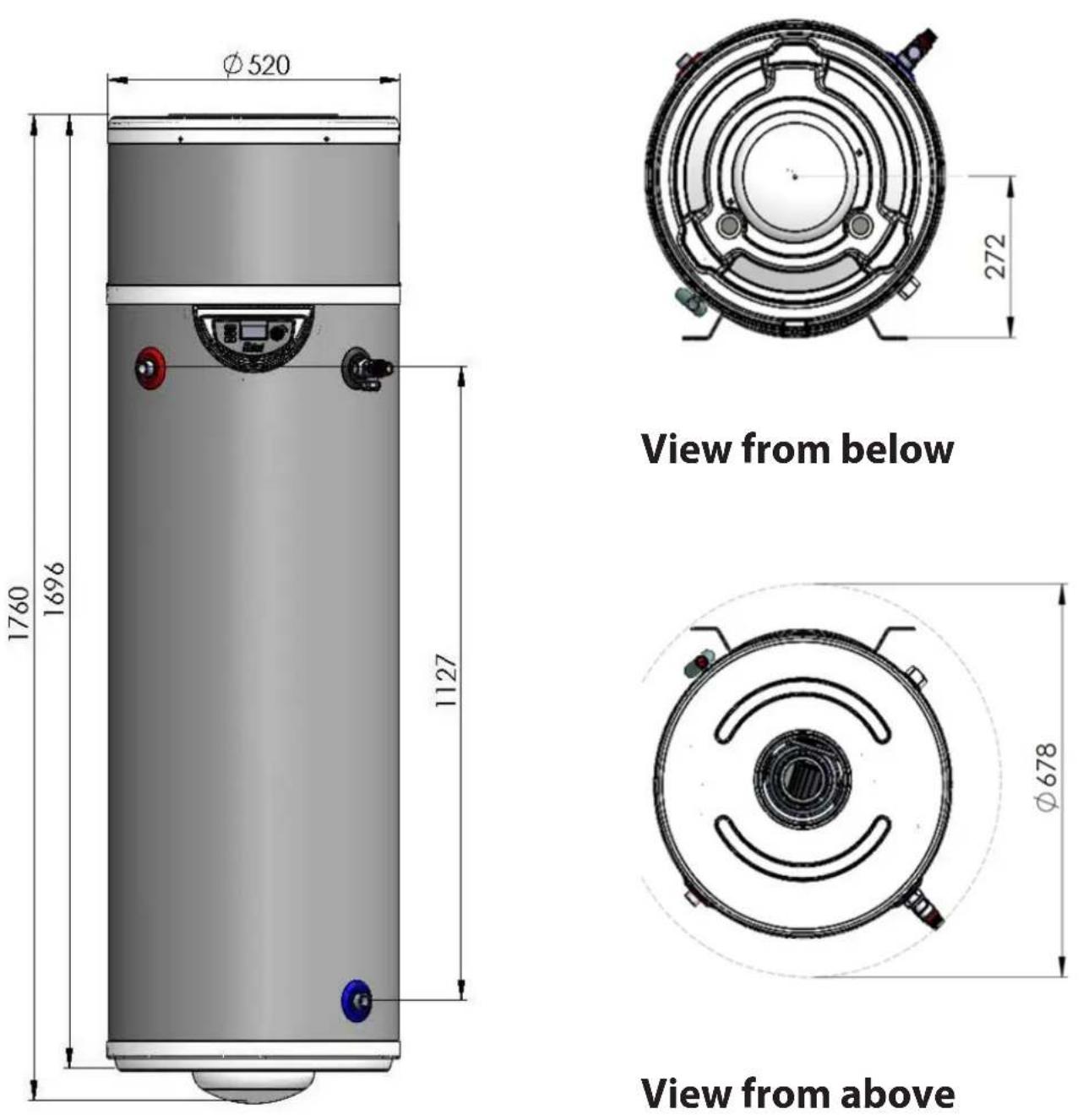
Figure 19: Edel Air Source Water Heater Dimensions (for reference
| Edel Air Source Water Heater - Dimensions | ||
| Reference EDL170L | ||
| Capacity [l] 170 | ||
| Hot Water Capacity [l]* 170 | ||
| Weight - Empty [kg] 58 | ||
| Weight - Full [kg] 228 | ||
| Heat Up Time [hh:mm]* 10:24 | ||
| Heat Loss [kWh/24h] 1.95 | ||
| Height [mm] A 1760 | ||
| Outer Diameter [mm] 520 | ||
| Condensate Pipe [mm] B 1025 | ||
| Hot Water Outlet [mm] C 900 | ||
| T&P Valve [mm] D 900 | ||
| Cold Water Inlet [mm] E 155 | ||
Table 8: Edel Air Source Water Heater Product
| GDC Group Ltd | Edel Air Source Water Heater - Product Fiche |
| Reference | EDL170L |
| Load Profile - Primary | M |
| Energy Rating | A+ |
| COP | 2.85 |
| Thermostat Setting | 55°C |
| Sound Pressure level at 1m [dB(A)] | 36 |
| Average Climatic Conditions | |
| Average Energy Consumption [kWh] | 426 |
| Water Heating Efficiency [%] | 120 |
| Daily Electricity Consumption [kWh] | 2.05 |
| Warmer Climatic Conditions | |
| Annual Energy Consumption [kWh] | 398 |
| Water Heating Efficiency [%] | 127 |
| Daily Electricity Consumption [kWh] | 1.84 |
| Cooler Climatic Conditions | |
| Annual Energy Consumption [kWh] | 485 |
| Water Heating Efficiency [%] | 105 |
| Daily Electricity Consumption [kWh] | 2.21 |
Table 9: Edel Air Source Water Heater Product
*Cylinder is tested in accordance with EN12897:2016
| Edel Air Source Water Heater - Product Features | |
| Materials | |
| Inner cylinder Stainless steel | |
| Outer cylinder Plastic | |
| Inlet/outlet Stainless steel | |
| Insulation 50mm PU foam (GWP=1, ODP=0) | |
| Maximum Operating Conditions | |
| Potable water temperature 65°C via immersion, 55°C via compressor alone | |
| Operating pressure 3 bar | |
| Maximum design pressure 6 bar | |
| Heat Pump max. pressure 25 bar | |
| Cold Water Supply | |
| Minimum dynamic pressure 1.5 bar | |
| Maximum pressure 12 bar | |
| Minimum flow rate 15 l/min | |
| Connections | |
| Cold water inlet M 3/4" stainless steel | |
| Hot water outlet M 3/4" stainless steel | |
| Air pipe diameter (inlet and outlet) | Insulated 80/125 concentric ducting |
| Immersion Heater | |
| 1 1/4 M BSP 1.2 kW@240V | |
| Ventilation | |
| Air flow rate 90 to 140 m | 3/h |
| Air temperature | -7°C to 35°C |
| Max. air pipe length | Rigid piping: Refer to section 6.7 ductwork calculation |
| Condensates flow rate | 0.3 L/h |
| Condensates drainage pipe | 18/23 mm |
| Safety Components | |
| Pressure reducing valve and strainer | 3 bar |
| Expansion relief valve | 6 bar |
| Temperature and pressure relief valve | 7 bar/90°C 1/2" BSP |
| Factory pressure test | 12 bar |
| Integrated electrical back-up power | 1200W (safety setting = 85°C) |
| Approvals | |
| KIWA approval number - 1701712 | |
| Guarantee | |
| Inner cylinder | 5 years |
| Immersion heaters | 2 years - excluding the effects of lime scale or other water borne contaminants |
| Other components | 2 years - excluding expansion vessel membrane pressure |
Table 10: Edel Air Source Water Heater Product
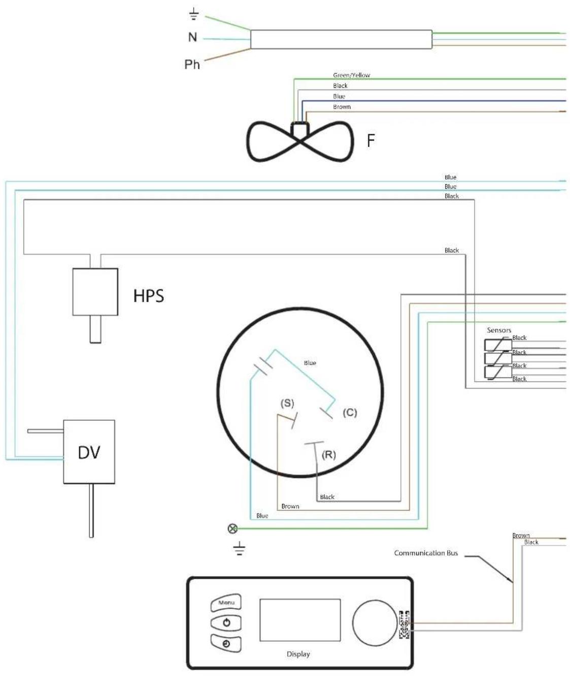
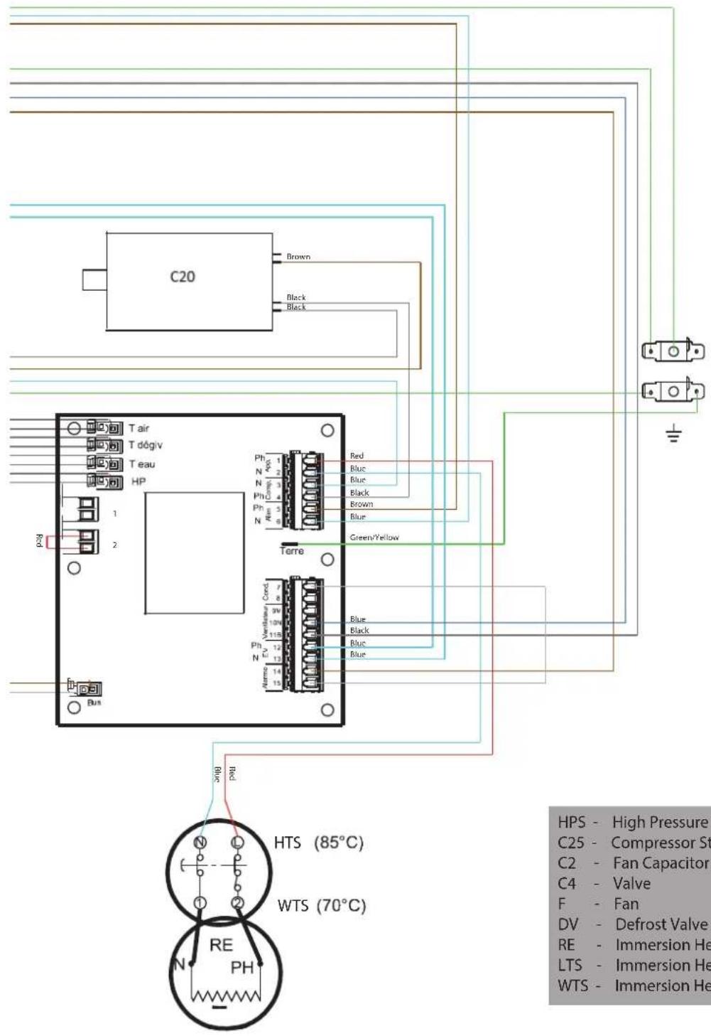
HPS - High Pressure Switch
C25 - Compressor Start Capacitor
C2 - Fan Capacitor
C4 - Valve
F - Fan
DV - Defrost Valve
RE - Immersion Heater
LTS - Immersion Heater Safety Cut-out
WTS - Immersion Heater Water Temp. Stat
MAINS PRESSURE HOT WATER STORAGE SYSTEM COMMISSIONING CHECKLIST
This Commissioning Checklist is to be completed in full by the competent person who commissioned the storage system as a means of demonstrating compliance with the appropriate Building Regulations and then handed to the customer to keep for future reference.
Failure to install and commission this equipment to the manufacturer's instructions will invalidate the warranty, but does not affect statutory rights.
Customer Name Telephone Number
Address
Cylinder Make and Model
Cylinder Serial Number
Commissioned by (print name) ____ Registered Operative ID Number ____
Company Name Telephone Number
ALL SYSTEMS
What is the incoming static cold water pressure at the inlet to the system? psi
Has a strainer been cleaned of installation debris (if fitted)? Yes No
Is the installation in a hard water area (above 200ppm)? Yes No
If yes, has a water scale reducer been fitted? Yes □No □
What type of scale reducer has been fitted?
What is the hot water thermostat set temperature? ____ °C
What is the maximum hot water flow rate at set thermostat temperature (measured at high flow outlet)? ____l/min
Time and temperature controls have been fitted according to CSA Standards and local codes? Yes
What is the hot water temperature at the nearest outlet? ____ °C
All appropriate pipes have been insulated up to 1 metre or the point where they become concealed Yes
Where is the pressure reducing valve situated (if fitted)?
What is the pressure reducing valve setting? ____ psi
Has a combined temperature and pressure relief valve and expansion valve been fitted and discharge tested? Yes □ No □
The tundish and discharge pipework have been connected and terminated according to CSA Standards and local codes? Yes
Are all energy devices fitted with a cut out device? Yes □ No □
ALL INSTALLATIONS
The hot water system complies with the appropriate CSA standards and local codes Yes
The system has been installed and commissioned in accordance with the manufacturer's instructions Yes
The system controls have been demonstrated to and understood by the customer Yes
The manufacturer's literature, including this Checklist and Service Record, has been explained and left with the customer Yes
Commissioning Engineer's Signature
Customer's Signature
(To confirm satisfactory demonstration and receipt of manufacturer's literature)
SERVICE RECORD
It is recommended that your hot water system is serviced regularly and that the appropriate Service Record is completed.
Service Provider
Before completing the appropriate Service Record below, please ensure you have carried out the service as described in the manufacturer's instructions.
SERVICE 1 Date
Engineer Name
Company Name
Telephone Number
Comments
Signature
SERVICE 2 Date
Engineer Name
Company Name
Telephone Number
Comments
Signature
SERVICE 3 Date
Engineer Name
Company Name
Telephone Number
Comments
Signature
SERVICE 4 Date
Engineer Name
Company Name
Telephone Number
Comments
Signature
SERVICE 5 Date
Engineer Name
Company Name
Telephone Number
Comments
Signature
SERVICE 6 Date
Engineer Name
Company Name
Telephone Number
Comments
Signature
SERVICE 7 Date
Engineer Name
Company Name
Telephone Number
Comments
Signature
SERVICE 8 Date
Engineer Name
Company Name
Telephone Number
Comments
Signature
SERVICE 9 Date
Engineer Name
Company Name
Telephone Number
Comments
SERVICE 10 Date
Engineer Name
Company Name
Telephone Number
Comments
Signature
Signature
Disregarding the instructions given in this manual in its entirety and any relevant regulations, standards and codes of practice will void the guarantee of this product. Glen Dimplex reserve the right to revise products, literature and guarantee terms without prior notice due to a policy of continuous improvement.
To speak to customer services please contact:
Glen Dimplex UK LTD.
Millbrook House Grange Drive, Hedge End,
Southampton SO30 2DF
Telephone: +44 [0]344 879 3588
Fax: 0844 879 3583
Email: customer.services@glendimplex.com
Or
Glen Dimplex Europe Limited
Airport Road, Cloghran
Co. Dublin K67 VE08
ROI +353 [0]1 842 4833
Email: serviceireland@glendimplex.com
- DCDimplex
- Air Source Heat Pump Water Heater
- Manual Warnings 4
- Safety Information 4
- Introduction 5
- Scope of Delivery 5
- Pre-Installation Advice 5
- Installation
- Set-Up and Use 15
- Maintenance 22
- Control App 28
- Warranty 29
- Technical Data and Product Fiche 30
- Manual Warnings
- Safety Information
- User Safety
- General Safety
- Introduction
- Dimplex Control
- Scope of Delivery
- Pre-Installation Advice
- Handling
- Storage
- Unpacking
- Keep the transport bag out of reach of children (risk of suffocation).
- Pipework
- Taps and Fittings
- Risk Assessment
- Siting Considerations
- It is PROHIBITED:
- It is PROHIBITED to install the appliance
- Installation
- On-ground Installation
- Cold Water Supply
- Building Regulation G3 Discharge Requirements
- Discharge Pipe D2
- Worked Example
- Termination of discharge pipe
- Product Disposal
- Materials:
- Connections & Fasteners:
- Safety & Control:
- Correctly Siting the Water Heater
- Cold Water Inlet with Inlet Group
- Install the Inlet Group
- Expansion Vessel
- Balanced Cold Water Supply
- Drain Valve
- Hot Water Outlet
- Thermostatic Mixing Valve
- Pipe Insulation
- Discharge Pipes from Safety Devices
- Discharge Pipe D1
- Discharge Pipe D2
- Tundish
- Note: It is important that the tundish is positioned away from any electrical components.
- Immersion Heater
- Air Connection
- Dimplex does not take any responsibility for issues caused by poor ducting design or installation.
- Dimplex does not take responsibility for installation and the operating efficiency of the appliance when installed outside the scope of the guidelines provided in this document.
- Ducting Design
- Worked Example
- Ducting Installation
- Direct access
- DCimplex
- Offset access
- Fixing
- Draining the Condensate
- Electrical Connections
- Accessing Electrical Connections
- Electricity Provider Contact
- Connecting the PV Function
- Set-Up and Operation
- Commissioning
- Deterioration risk: The water tank must be filled before the appliance is switched on or connected to a power supply.
- Using your Hot Water Heat Pump
- Control Box
- Setting the Language
- Setting the Time
- Setting the Water Temperature
- Holiday Mode
- BOOST Function (for occasional use)
- Electric Mode
- (to operate with electrical backup)
- Programming
- Installer Menu
- PV Mode
- N.B:
- Adjusting the Operating Settings
- Anti-Bacteria (Anti-Bact)
- Factory Setting = No
- Fan Mode
- Factory Setting = 1
- Minimum Temperature
- Shedding
- Maximum Time
- Locking the Keyboard
- Permanent and automatic locking
- Manual Locking from the Main Screen
- Resetting Parameters
- Reading Display
- Counters (Meters)
- Maintenance
- DHW Cylinder
- Heat Pump
- Air intake & Exhaust
- Heat Pump Condensation
- Electrical Connections
- Troubleshooting
- Error Message Codes: Errors, Solutions and Operating in case of Error
- Control App
- Home Screen
- Holiday Mode
- Schedule Control
- Hygiene Mode
- Warranty
- Warranty Limits
- Exclusion from Warranty
- Use
- Handling
- Installation Site
- Electrical Connections
- Hydraulic Connections
- Accessories
- MAINS PRESSURE HOT WATER STORAGE SYSTEM COMMISSIONING CHECKLIST
- ALL SYSTEMS
- ALL INSTALLATIONS
- SERVICE RECORD
- Glen Dimplex UK LTD.
- Glen Dimplex Europe Limited
Brand : DIMPLEX
Model : EDL170-520RF
Category : Heat pump