TNDN32 - Heat pump DIMPLEX - Free user manual and instructions
Find the device manual for free TNDN32 DIMPLEX in PDF.

User questions about TNDN32 DIMPLEX
0 question about this device. Answer the ones you know or ask your own.
Ask a new question about this device
Download the instructions for your Heat pump in PDF format for free! Find your manual TNDN32 - DIMPLEX and take your electronic device back in hand. On this page are published all the documents necessary for the use of your device. TNDN32 by DIMPLEX.
USER MANUAL TNDN32 DIMPLEX
DCDimplexrenewables®
A world of expertise
CI/SFB (56)

natural_image
Green globe illustration showing continents and oceans (no text or symbols)Tried. Tested. Trusted.

natural_image
Composite image showing a bright green field with sun and a blue sky, alongside three inset photos of different air conditioning units (no text or symbols visible)Dimplex Heat Pumps
Working with nature's energy for environmentally friendly heating
A name you can trust
For over 60 years, Dimplex has been making life more comfortable, in more ways, in more places than any other company. Dimplex has long been the number one name in electric heating technology, having established an unmatched reputation for quality, reliability and innovation.
The Dimplex brand is well known in both the public and private sectors, particularly with local authorities, housing associations and major home builders where the brand has become synonymous with a commitment to excellence and customer satisfaction.

natural_image
Exterior view of a modern single-story house with solar panels installed on the roof, surrounded by greenery and outdoor furniture (no signage or text visible)Contents
Our experience
For Dimplex, there's nothing new about renewables. As part of the worldwide Glen Dimplex Group, Dimplex has been producing innovative heat pumps for over 30 years with thousands of installations throughout Europe.
We are committed to developing heating solutions which utilise sustainable and renewable energy with the aim of reducing CO_2 emissions and their impact on the environment.
From our manufacturing plants in the UK and Germany, Dimpl ex produces the widest range of heat pumps available on the UK market and leads the way in the development of energy efficient heat pump technologies.
Quality assured
Over the years, Dimplex has established strong relationships with its customers in all aspects of the construction and heating industries. Today Dimplex electric heating and heat pump systems are operating efficiently across the UK in schools, offices, social housing and libraries in both private and public sectors.
In order to ensure the highest levels of quality and to provide peace of mind, Dimplex has an established network of Accredited Heat Pump Installers, all accredited under the Microgeneration Certification Scheme and fully trained and experienced in the installation of Dimplex heat pump products.
No other company can provide the depth of range, expertise and service back-up for economical, sustainable heating solutions.

text_image
produces mps available the way y efficient established customers ction and complex mp ently fices, in both4 Why choose a heat pump?
5 The global challenge
6 Harnessing nature's energy
7 Trusted technology
8-9 Applications
10-11 Financial incentives
12-13 Range overview
14-23 Air source heat pumps
24-31 Ground source heat pumps
32-33 Reversible heat pumps
34-35 Swimming pool heat pumps
36-43 Heat pump accessories
44 Installers
45 Support information
46-55 Technical specifications
Why choose a heat pump?
In the context of ever rising energy costs and climate change, every household is in need of a heating technology that is future-proof, cost-effective and independent of fossil fuels.
Using nature's energy
Heat pumps make a significant contribution towards solving the problems associated with increasingly scarce and evermore expensive energy resources – supplying more energy than they consume by tapping into the freely available, inexhaustible solar energy stored in the earth, the ambient air or water and converting this for use in a heating system.
In fact, up to 75% of the energy needed by the heating system is extracted from the environment, so the only energy required is electricity needed to drive the heat pump compressor.
Put another way, for every 1kWh of electricity used to run the heat pump, up to 4kW of useful heat is provided, giving the heat pump an efficiency of up to 400%.
A low carbon heating solution
Whenever fossil fuels such as gas or oil are burnt, carbon dioxide is released. CO_2 is the principle contributor to the greenhouse effect which is leading to long term climate change.
However as heat pumps extract as much as 75% of their heating energy from the environment, building carbon emissions for heating can be reduced by as much as 50% compared with gas fuelled heating systems.
This is an obvious benefit when considering building regulations Part L compliance, planning obligations requiring minimum contributions from renewable energy and EcoHome/Code for Sustainable Homes ratings.
Low running costs Low ownership costs
The considerable contribution from renewable energy sources also helps to provide running cost savings over fossil fuelled heating systems and arguably more importantly, future proofs the system against future energy price increases.
But fuel costs are only part of the story. Unlike gas and oil based systems, heat pumps require no costly regular maintenance or annual safety inspections. And because a heat pump has a reasonable life expectancy of 20 – 25 years, typically twice that of a boiler, the investment costs can be recovered over a longer period meaning the ownership costs over the working life of the system are demonstrably lower.
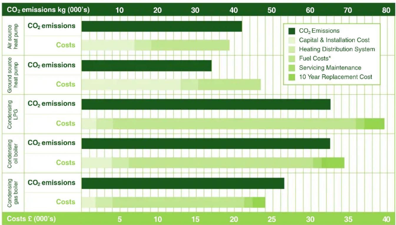
Lifetime ownership cost and CO_2 emissions comparison
bar
| CO2 emissions | CO2 emissions (kg 000's) | Costs (£ 000's) | |---|---|---| | Air source heat pump | 41 | 5 | | Ground source heat pump | 34 | 19 | | Condensing LPG | 65 | 4 | | Condensing oil boiler | 64 | 34 | | Condensing gas boiler | 60 | 24 |Figures compared over a 20 year period for space and water heating for a typical 3 bed semi detached home (new build)
*Fuel costs based on 2012 gas and electricity prices
The global challenge
Climate change is the greatest threat facing the planet, with rising temperatures causing more droughts, floods and storms causing sea levels to rise.
In the last 20 years, use of the Thames Barrier (designed to protect London from flooding) has risen from once every two years to six times a year.
According to the latest figures from the Intergovernmental Panel on Climate Change (IPCC), 11 of the last 12 years rank in the 12 warmest years since 1850 and 2005 was the hottest year on record. The impacts of weather related disasters are also increasing two to three times more rapidly than impacts due to earthquakes.
Most scientists agree that climate change is largely due to human activity, mainly the increased use of fossil fuels. The main human influence on the global climate is likely to be emissions of greenhouse gases such as carbon dioxide ( CO_2 ) and methane.
What difference can we make?
Emerging nations such as China and India are today consuming more and more energy to fuel their enormous economic growth, so what difference can a tiny island like the UK make?
Indeed if the UK became 100% zero carbon tomorrow, it would take China less than 3 months to replace the UK's carbon emissions.

natural_image
World map silhouette in green, showing continents and oceans (no text or labels)However, carbon emissions per capita in the UK are one of the highest in the world – in fact if every nation had such high emissions per head of population, global emissions would increase 3-fold.
So the UK has a responsibility to demonstrate to the developing nations of the world that it is possible to achieve economic growth while reducing its carbon emissions and environmental impact.
Planning for the future
Currently we all have the freedom to choose whether or not to voluntarily install greener technologies to reduce our homes' or businesses' carbon footprint. Some experts predict that greener technologies will be compulsory through legislation in the near future as has the recycling of our rubbish.
The sooner you switch, the sooner you can start to save money and the planet.

natural_image
Five transparent water droplets on a green leaf, one with Earth visible inside (no text or symbols)Harnessing nature's energy
Our environment is full of energy, even at sub-zero temperatures there is plenty of energy available.
Heat pumps use conventional refrigeration technology to extract the sun's energy stored in the environment and raise it to a temperature suitable for heating purposes.
This method even works in the middle of winter at temperatures as low as -25°C.

natural_image
Hand forming a partial heart shape against a bright sun and blue sky (no text or symbols)One system for all types of heat sources
Dimplex heat pumps offer you two different future-proof heat sources – outside air or the ground.

natural_image
Blue sky with scattered white clouds, no text or symbols visibleAir source heat pumps extract heat from the outside ambient air all year round, even at temperatures as low as -25°C.

natural_image
A large green tree with dense foliage standing in a vast green field under a blue sky with scattered clouds.Ground source heat pumps extract heat from the earth all year-round via ground heat collectors buried beneath the ground.
Trusted technology
Using nature's energy efficiently
Heat pumps are among the most efficient heating and hot water systems available today. Approximately 75% of the energy needed for heating comes from the environment. This means that for every 1kWh of electricity used to power the heat pump compressor, between 3 and 4 kWh of heating energy are produced, giving the heat pump an efficiency of 300 – 400% or higher.
The heat pump's "efficiency" is known as its "Coefficient of Performance" (CoP). This is simply a ratio between the proportion of the total energy supplied that can be extracted from the environment and the amount supplied by electricity to run the heat pump compressor. The higher the CoP, the more "free" environmental energy the heat pump is using!
Heat pump system components
A heat pump heating system consists of 3 components: the heat source, the heat pump itself and a heat distribution and storage system.
Heat pumps are able to produce more energy than they consume by using the conventional refrigeration cycle to absorb heat from the environment and raise it to a suitable level for heating.

flowchart
graph LR
    A["1 Source: from Air or Ground 75%"] --> B["3 Evaporator"]
    C["2 Source: National Grid 25%"] --> D["6 Condenser"]
    B --> E["4 Heat Pump"]
    D --> F["5"]
    D --> G["6"]
    E --> H["100% Heat Pump"]
    F --> H
1 75% of the energy is taken from the environment i.e. the air or ground and transferred to the heat pump.
3 The energy from the air or ground is transferred to the refrigerant inside the heat pumps evaporator. This causes the temperature of the refrigerant to rise and change state from liquid to gas.
5 A heat exchanger (condenser) then extracts the heat energy from the hot refrigerant to heat water for central heating, underfloor heating or domestic hot water.
2 25% of the energy is sourced from the national grid in the normal way of supplying your electricity. This is used to operate the heat pump but with very low consumption.
4 The refrigerant gas is then compressed, using an electrically driven compressor, reducing its volume but causing its temperature to rise significantly.
6 After giving up its heat energy the refrigerant turns back into a liquid and is able to absorb energy from the environment, allowing the cycle to begin again.
Built to last

text_image
Technical diagram of a gasifier unit with labeled components and control panelPowerful, quiet, safe and reliable. The "heart" of the heat pump is the Copeland scroll compressor, providing high levels of efficiency, reliability and low noise operation.
2 Always in control. The WPM heat pump manager monitors, regulates and controls the entire system to ensure optimum performance and efficiency for heating, domestic hot water and where applicable, cooling.
3 Evaporator. Large surface area plate heat exchangers allow for efficient heat transfer of energy from the environment. They are compact, efficient and reliable.
4 Insulated casing. Sound insulation around the insides of the heat pump casing reduce operating noise to a minimum.
The natural solution
...with so many applications
Increasingly stringent legislation and escalating fuel costs make heat pumps the ideal choice for so many applications, both domestic and non-domestic.
Whether for new build or retro-fit, for self builders, commercial housing developments or schools; for heating, cooling or for use with underfloor heating systems or radiators, heat pumps provide the ideal low carbon energy solution, whatever the application.

natural_image
Exterior view of a brick house with a chimney and green landscaping, labeled 'Social Housing' at the bottom (no other text or symbols visible)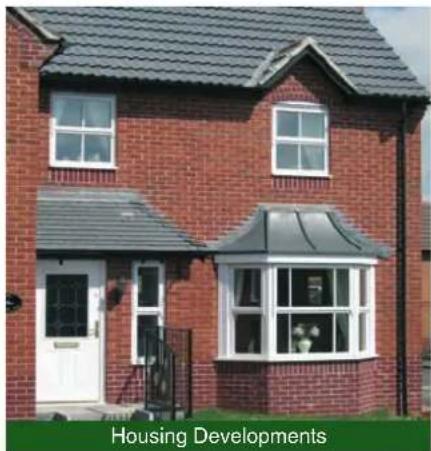
natural_image
Exterior view of a two-story brick house with a gray roof and white door, labeled 'Housing Developments' at the bottom (no other text or symbols visible)
natural_image
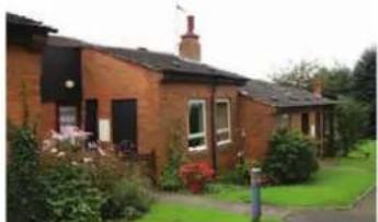
Exterior view of a modern residential building with red brick facade and adjacent green courtyard (no signage)Social Housing
- Ideal for stock refurbishment projects as a means to meeting Decent Homes standards and tackling fuel poverty, particularly in off gas-grid areas
- Significant CO_2 emission savings over other fuels, helping compliance with higher levels of the Code for Sustainable Homes
• Negligible maintenance requirements
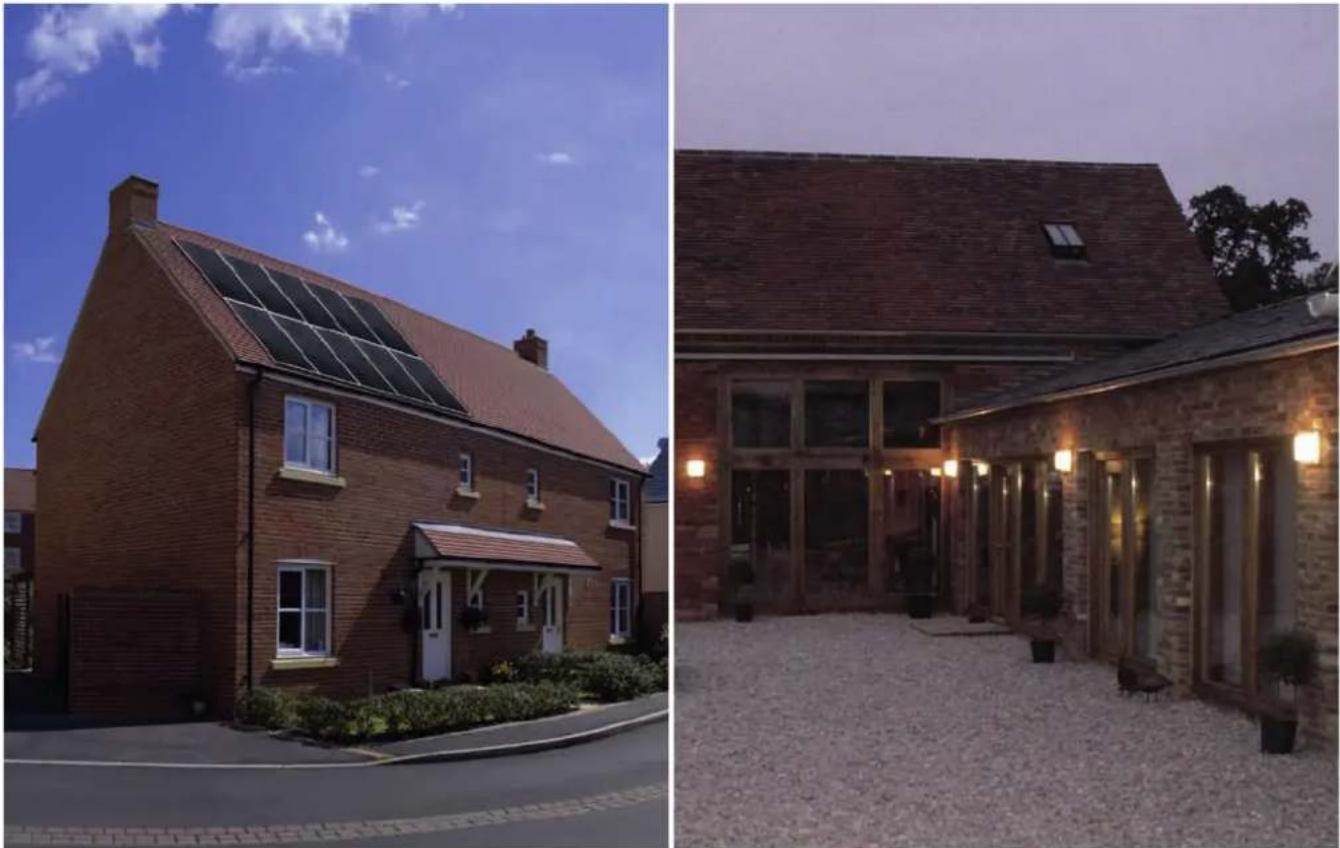
Housing Developments
- Up to 50% CO _2 savings over fossil fuelled systems helps towards Building Regulations Part L/Code for Sustainable Homes compliance
- Heat pumps formally accepted as a “Renewable” technology so meet local planning authority requirements to incorporate renewable energy in new buildings (Planning Policy Statement 22/“Merton Rule”)
• Will make a significant contribution towards high EPC scores - Highly marketable "Eco" credentials and low end-user running costs for heating/hot water

natural_image
Exterior view of a modern brick house at dusk with illuminated windows and a sign reading 'Self Builders' (no other text or symbols visible)Flats and Apartments
• Multiple high output ground or air source units commonly linked together to provide central plant space/water heating for multi-occupancy dwellings
- Up to 50% CO _2 savings over fossil fuelled systems helps towards Building Regulations Part L/Code for Sustainable Homes compliance
• Significant cost reduction over installing individual heat pumps in each apartment
• Efficiency benefits of communal systems recognised by SAP
Self Builders
- 50% lower CO _2 emissions than gas boilers, help make a significant contribution towards Building Regulations Part L compliance, particularly with contemporary styled homes with large glazed areas
• High renewable energy contribution helps ease planning consent - Requires electrical infrastructure only – ideal for off gas-grid areas
• Makes a significant contribution to lower home energy bills - Can be used for energy-efficient swimming pool heating in the summer months

text_image
SCARNING PRIMARY Schools small enough to care - age enough to inspire Scaring VC Primary School office@scaring.no.uk/uk 362 892065 1362 692065 Education
text_image
Moorland Centre Leisure and ResidentialEducation
- Ongoing schools' building programmes can benefit from heat pump systems that improve the environmental footprint and reduce running and operational costs
- Able to meet governmental targets for 60% renewable energy in new schools projects
• Can be utilised to provide a valuable learning tool for students
• Income generation through Renewable Heat Incentive (RHI)
Retail and Commerce
- Heat pumps meet the increasing local authority requirements to incorporate renewable energy within the energy profile of new buildings (Planning Policy Statement 22/“Merton Rule”)
• Significant CO _2 savings over fossil fuelled systems help towards building regulations compliance - Many developers investing in "green" buildings with low energy costs in the knowledge that they can attract premium rent/lease values
- Ability to provide energy efficient heating and cooling from a single system optimises capital investment
• Income generation through Renewable Heat Incentive (RHI)
Leisure and Residential
- Growing take up in the leisure/hotels sector to reduce consumption and CO_2 emissions, particularly where mains gas is not available
• Typical uses include swimming pool heating, hot water production, space heating and cooling - Reversible units with heat recovery ideal for utilising waste heat for swimming pool or water heating
- Multiple air source units commonly linked together to provide central plant space/water heating for multi-occupancy dwellings such as care homes
• Income generation through Renewable Heat Incentive (RHI)

natural_image
Exterior view of a modern building with glass facade and awning, labeled 'Retail and Commerce' at bottom (no other signage)Public and Community
-
Dimplex heat pumps are already installed in a wide range of public and community buildings, both new build and refurbished, allowing them to benefit from lower fuel bills and reduced CO_2 emissions
• Typical installations include: -
Visitor centres
- Village halls
• Community centres
• Emergency service buildings (fire stations, mountain rescue centres, lifeboat stations) - Libraries
- Places of worship
• Income generation through Renewable Heat Incentive (RHI)

natural_image
Exterior view of a modern building with solar panels and landscaping under a blue sky (no signage or text visible)Financial incentives
Grants and Funding
The era of grant funding schemes for heat pumps is beginning to come to an end, however as the Government endeavours to meet its target of 15% of total UK energy consumption being generated from renewable source by 2020, schemes are being put in place to encourage the uptake of renewable heat technologies.
Renewable Heat Incentive (RHI)
The Renewable Heat Incentive (RHI) announced in March 2011, is aimed at encouraging people to install renewable heating technologies and is the first financial support scheme for renewable heat in the world. Administered by OFGEM the scheme has been split in to two phases:
Phase 1
This phase of the scheme opened for applications on November 28, 2011 and is focussed on the non-domestic sector (industrial, business and public sector) as it accounts for 38% of the UK's emissions. For the domestic sector a one off incentive has been put in place, the Renewable Heat Premium Payment (RHPP) to provide householders with financial support to install renewable heating technology. Currently only the technologies listed within the EU Renewable Energy Directive are supported. As listed below:
- solid biomass and solid biomass contained in municipal waste (including CHP),
• ground and water source heat pumps,
• geothermal (including CHP),
• solar thermal (at capacities of less than 200 kWth), - biogas combustion (except from landfill gas but including CHP; at capacities of less than 200 kWth) biomethane injection.
Note: Air source heat pumps are not currently supported.
Participants also need to meet several other eligibility requirements which are explained in the Guidance document. These include demonstrating that the heat is used for an eligible purpose, that metering arrangements are appropriate, and that grants have not been received for certain purposes.
The tariffs will be paid for 20 years to eligible technologies that have been installed since 15th July 2009 with
payments being made for each kWh of renewable heat which is produced. Once in the scheme the level of support an installation will receive is fixed and adjusted annually with inflation.
Phase 2
The second phase is likely to see the scheme expanded to include additional technologies as well as long term support for house holders. DECC expects that Phase 2 will be up and running by Summer 2013 which represents a significant slippage from the original intended start date so to accommodate this slippage a second phase of RHPP has been put in place, effective from 2 April 2012.
Consultations are taking place looking at the inclusion of further commercial technologies such as Air Source Heat pumps and budget control measures; an interim budget control mechanism for Phase 1 and for Phase 2, a longer-term flexible degression-based cost control mechanism to automatically reduce tariffs should spending against the overall budget or uptake of certain technologies exceed forecasts.
RHI at a glance
- Commercial, public sector, not for profit and communal residential installations only
- Dimplex eligible technologies – ground source heat pumps and solar thermal
- Tariffs – paid quarterly, guaranteed for 20 years, index linked
Rates:
• GSHP <100kWth - 4.7p/kWh100kWth - 3.4p/kWh
• Solar Thermal 8.9p/kWh
• Installations under 45kWth must be MCS certified (equipment and installer)
• Installation must have been completed after 15 July 2009 - Systems must be heat metered payments are based on meter readings submitted
• Scheme administered by OFGEM
Dimplex Renewable Energy Finance
Dimplex Renewable Energy Finance has been specifically designed to help not-for-profit organisations including local authorities, schools and housing associations overcome the need for initial capital investment when installing heat pump systems.
The scheme is designed to provide a solution for organisations looking to implement renewable energy technologies but for whom the initial capital outlay, even where grants are available, could make going ahead with the project an impossibility, by allowing investment costs to be repaid over a period of years funded through the savings in energy costs the heat pump will provide.
Benefits of the scheme include:
- Can be used in place of grants to cover entire project costs
- Project costs covered in full with no up-front capital outlay
• Investment costs recovered from energy cost savings on an ongoing basis - Allows project schedules to be accelerated by removing budgetary constraints
- Flexible payment schedules and accounting structure based on client needs
Reduced Energy Costs
In addition to reducing a property's carbon footprint the installation of a heat pump can also bring financial rewards in the form of lower energy bills and potential income through the Renewable Heat Incentive scheme.
The typical scenarios on the following page demonstrate just how much you could save.

Property size: (63m²)
Space heating demand: 8248kWh
DHW demand: 2000kWh
TOTAL heating demand: 10248kWh
Fossil fuel heating costs
| 2 bedroom end terrace house | kWh/yr | Fuel cost/kWh |
| LPG space heating | 11783 | |
| LPG water heating | 5714 | |
| Total LPG heating | 17497 | £1518 |
| Oil space heating | 11783 | |
| Oil water heating | 5714 | |
| Total oil heating | 17497 | £1182 |
6kW ASHP
6kW ASHP
Potential costs/savings using a heat pump
| Heat emitter type | Space heating kWh/yr | Water heating kWh/yr | Total heating kWh/yr | Running costs/year | Yearly savings vs LPG | Yearly savings vs oil |
| Radiators | 3437 | 833 | 4270 | £541 | £977 | £641 |
| SmartRads | 2426 | 833 | 3583 | £454 | £1064 | £728 |
| Heat emitter type | Space heating kWh/yr | Water heating kWh/yr | Total heating kWh/yr | Running costs/year | Yearly savings vs LPG | Yearly savings vs oil |
| Radiators | 2661 | 645 | 3306 | £419 | £1099 | £763 |
| SmartRads | 2229 | 645 | 2874 | £364 | £1153 | £818 |

natural_image
Illustration of a house with green roof and two windows, no text or symbols presentProperty size: (150m²)
Space heating demand: 18273kWh
DHW demand: 3500kWh
TOTAL heating demand: 21773kWh
Fossil fuel heating costs
| 5 bedroom detached house | kWh/yr | Fuel cost/kWh |
| LPG space heating | 26104 | |
| LPG water heating | 10000 | |
| Total LPG heating | 36104 | £3132 |
| Oil space heating | 26104 | |
| Oil water heating | 10000 | |
| Total oil heating | 36104 | £2439 |

9kW ASHP
9kW GSHP
Potential costs/savings using a heat pump
| Heat emitter type | Space heating kWh/yr | Water heating kWh/yr | Total heating kWh/yr | Running costs/year | Yearly savings vs LPG | Yearly savings vs oil |
| Radiators | 7614 | 1458 | 9072 | £1149 | £1982 | £1290 |
| SmartRads | 6091 | 1458 | 7549 | £957 | £2175 | £1482 |
| Heat emitter type | Space heating kWh/yr | Water heating kWh/yr | Total heating kWh/yr | Running costs/year | Yearly savings vs LPG | Yearly savings vs oil |
| Radiators | 5895 | 1129 | 6540 | £829 | £2303 | £1610 |
| SmartRads | 4939 | 1129 | 5584 | £707 | £2424 | £1732 |
natural_image
Illustration of a green-roofed building with white doors and a large window (no text or symbols)Property size: (650m²)
Space heating demand: 720000kWh
DHW demand: 0kWh
TOTAL heating demand: 720000kWh
Fossil fuel heating costs
| Small commercial office block | kWh/yr | Fuel cost/kWh |
| LPG space heating | 102857 | |
| LPG water heating | n/a | |
| Total LPG heating | 102857 | £8922 |
| Oil space heating | 102857 | |
| Oil water heating | n/a | |
| Total oil heating | 102857 | £6948 |
40kW ASHP
40kW GSHP
Potential costs/savings using a heat pump
| Heat emitter type | Space heating kWh/yr | Total heating kWh/yr | Running costs/year | Yearly savings vs LPG | Yearly savings vs oil |
| Radiators | 30000 | 30000 | £3801 | £5121 | £3147 |
| SmartRads | 24000 | 24000 | £3041 | £5881 | £3908 |
| Heat emitter type | Space heating kWh/yr | Total heating kWh/yr | Running costs / year | RHI payment /yr | Yearly savings vs LPG | Yearly savings vs oil | Total benefits vs LPG | Total benefits vs oil |
| Radiators | 23226 | 23226 | £2943 | £3096 | £5979 | £4006 | £9075 | £7102 |
| SmartRads | 19459 | 19459 | £2466 | £3096 | £5826 | £4483 | £8922 | £7579 |
Range overview
Dimplex is setting new standards with its latest generation of heat pumps. With the widest range of heat pumps in the UK, no matter what your choice of energy source (ground or air), there will be a solution in the Dimplex range ideally suited to your needs.
Flexibility
Our heat pumps can be combined with a wide number of fully compatible system accessories, including buffer tanks and domestic hot water systems to provide complete flexibility in terms of system design.
To simplify specification and installation, a number of our heat pumps are also offered in packages which include heat pump ready cylinders and/or buffer tanks and all the components required to install a standard domestic system.
Performance
The Dimplex ethos is always to aim for the highest level of system efficiency, with our heat pumps designed to minimise energy use – no matter what the temperature or operating conditions.
Quality and Reliability
The international quality label for heat pump systems guarantees the highest environmental, safety and quality standards.
Control
The comprehensive Dimplex heat pump manager provides complete system control over multiple heating and hot water circuits and, where needed, cooling functions. Self explanatory display text provides simple operation.

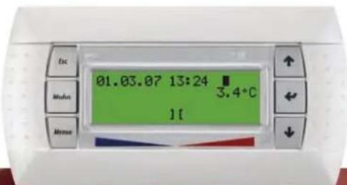
text_image
01.03.07 13:24 3.4°C 11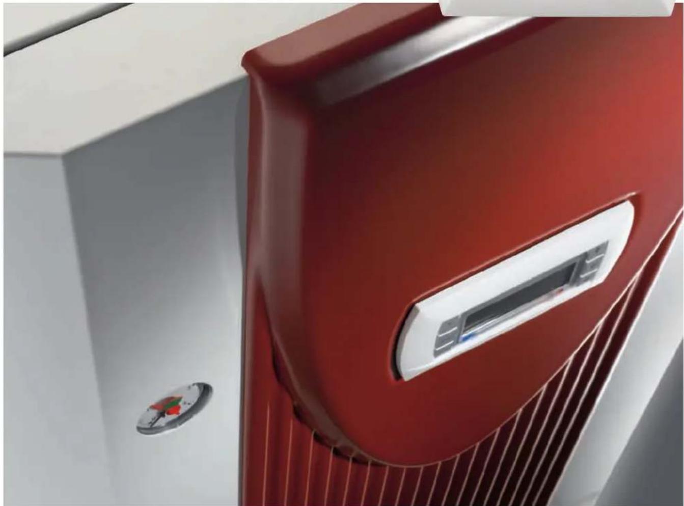
natural_image
Close-up of a red and white air conditioner unit with a circular button and ventilation grille (no visible text or symbols)| Air Source | Ground Source | |||||||||||||||
| Nominal Rating kW | Indoor or Outdoor | Phase | WPM Controller | Max. Flow Temp | Nominal Rating kW | Indoor or Outdoor | Phase | WPM Controller | Max. Flow Temp | |||||||
| Domestic | LAMI | Inverter |  | 6-16 O 1 | x | SIHME | High temperature |  | 4-11 | I | 1 | √ | 70 | |||
| LAMS | Heating & hot water |  | 9-16 | O | 1 | √ | 55 | SIME | Heating & hot water |  | 14 | I | 1 | √ | 58 | |
| LAPMS | High temperature |  | 8-14 | O | 1 | √ | 65 | SIKME | Integrated hydraulic components |  | 16 | I | 1 | √ | 55 | |
| Commercial | LATU | High efficiency |  | 17-60 | O 3 √* | 58-65 | SITE SITU | Heating & hot water |  | 18-130 | I | 3 | √ | 58-60 | ||
| LAAS | High output |  | 20-28 | O | 3 | √ | 55 | SIHTE | High temperature |  | 20-40 | I | 3 | √ | 70 | |
| LAPS | High temperature |  | 17-26 | O | 3 | √ | 65 | SITER+ SITUR+ | Heating & cooling |  | 30-130 | I | 3 | √ | 55 | |
| LATUR+ | Heating & cooling |  | 35-60 | O | 3 √* | Heat Pump Accessories:EC-Eau hot water cylindersBuffer cylindersHydraulic system accessoriesHeat pump managerSmartRadPassive coolingSolar integrationGround collector circuit manifolds and accessories | ||||||||||
| Swimming pool | LASMT |  | 10-15 | O | 1 | x | 40 | |||||||||
| LASTT |  | 22 | O 3 | x | 40 | |||||||||||
Air source heat pumps
Even cold air is full of energy and Dimplex air source heat pumps use the freely available heat in the ambient air to provide efficient heating and hot water at air temperatures as low as -25°C.
Because the source of heat – the air – is abundantly available all around us, air source heat pumps have the advantage of low installation costs and minimal space requirements, while relatively mild winter temperatures in the UK mean excellent levels of efficiency and performance are achieved throughout the year.

natural_image
Close-up of a dandelion seed head with dewdellis against a blurred green background (no text or symbols)Benefits of the outside air as a heat source
- Can be utilised all year round between -25°C and +35°C
• Always available and inexhaustible source of heat
• No requirement for the cost and land area of ground collectors - Ideal for new build or retro fit applications, especially where space is limited
- Can be used for heating, cooling, domestic hot water and swimming pools
Air source heat pumps – benefits of the UK climate
Compared with central Europe (where air source heat pumps are already very popular), the UK has a relatively moderate winter climate.
With average winter temperatures of around 5^ C, seasonal co-efficients of performance comparable with ground source heat pumps are achievable, without the additional cost of expensive ground loop systems having to be installed.
Average UK temperatures over 12 month period

line
| Month | maximum temperature (°C) | minimum temperature (°C) | |-------|--------------------------|--------------------------| | Jan | 6 | 0 | | Feb | 7 | 1 | | Mar | 10 | 3 | | Apr | 14 | 5 | | May | 18 | 8 | | Jun | 20 | 10 | | Jul | 22 | 12 | | Aug | 20 | 10 | | Sep | 18 | 8 | | Oct | 14 | 5 | | Nov | 10 | 3 | | Dec | 6 | 0 |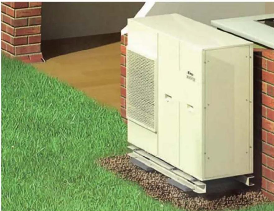
natural_image
Exterior view of a white energy unit labeled 'Dav MOTA' mounted on a green lawn next to a brick wall (no signage or text beyond label)Installation
Dimplex air source heat pumps are constructed from robust, powder-coated metal casings to provide year round protection against the elements.
The heat pump is connected to the indoor heating system simply by laying two heat insulated pipes and the electric connection cables under the ground.
Features/benefits
• No space is required inside the property
• Installation is relatively straightforward
• The heat source is easy to tap
- The weatherproof heat pump is installed on a sturdy concrete base
• The water pipes and electric cables are securely laid underground
Case studies
Heat pumps in action
Dimplex heat pumps have been installed in a wide variety of applications – two are featured here, but more are available on our website.
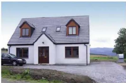
Scotland self builders warm to free energy with Dimplex
Energy efficient, low carbon heating is now taken for granted by the owners of a new build property in Scotland with the installation of a Dimplex 11kW air source heat pump providing all of their heating and hot water needs.
natural_image
Exterior view of a modern white house with gray roof and two brown windows, parked near gravel and distant hills (no signage or text visible)Installed at the side of the 160m ^2 , four bedroom property, the LA 11 MS provides enough heat for the water in a 300 litre tank and the under floor heating system delivering a room temperature of 22°C.
The owner's objective for the property was to have an energy efficient house and felt that a heat pump represented the most advanced and effective method for heating.
natural_image
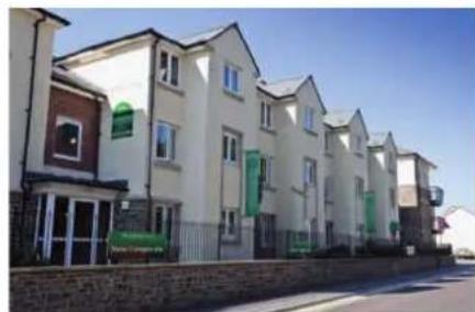
Exterior view of a row of modern residential houses under clear blue sky (no signage or text visible)Dimplex heat pumps score for McCarthy & Stone
McCarthy & Stone, the UK's largest builder of retirement homes, took the lead in energy savings by installing Dimplex heat pumps at a development of 41 apartments in Clevedon, Somerset and achieved level 3 of the Code for Sustainable Homes. Three 28kW Dimplex air source heat pumps provide a communal system, servicing the entire block, with each flat having its own metering and separate hot water cylinder.
Domestic air source heat pumps
Inverter driven air source heat pumps
Dimplex Air-Eau inverter driven air source heat pumps deliver market leading energy efficiency and performance with achievable CoPs of up to 4.7. With a range of inverter models with outputs from 6 – 16kW, Dimplex can provide a solution for most domestic applications from small, well-insulated new build homes, to retrofits in existing homes which have higher heat demands.
Easy to install, due to the range's monobloc configuration, the Air-Eau is the ideal choice for new developments looking to reduce CO_2 emissions, social housing refurbishment projects to tackle fuel poverty and the replacement of oil/LPG systems in larger private homes.
At the heart of the Air-Eau heat pump is a variable speed, inverter controlled compressor, which allows the heat levels delivered to be matched closely to the heating requirements of the building, as ambient temperatures change. This means that in cold weather heat pump capacity is maintained, eliminating any need for supplementary back up heating, while at warmer air temperatures, heat pump output can be reduced, helping to improve efficiency.

natural_image
Outdoor patio scene with a solar air conditioner unit, a glass of juice, and a table of bread and fruit (no visible text or symbols)
natural_image
Exterior view of a CDimplex inverter air conditioning unit (no signage or text beyond branding)
text_image
AIR eau
Air-Eau/LA MI
The Dimplex Air-Eau range of inverter-driven air source heat pumps are designed to match output to varying heating demand. With achievable CoPs of up to 4.7, the Air-Eau provides one of the most advanced, efficient and high performance air source heat pump ranges available.
Employing an inverter driven compressor to maximise heat pump efficiency enables the Air-Eau range to modulate the heat pump output to match the
heating demand, so at warmer air temperatures when heating demand falls the heat pump output is reduced, which helps to improve efficiency (CoP).
Available in 6, 9, 12 and 16kW variants, Air-Eau heat pumps are supplied as a fully integrated unit, including circulation pump and expansion vessel making installations easier to carry out and less time consuming. The Air-Eau models also come with the added advantages of low starting current (phased compressor start up) and low noise levels.
| Model | LA 6 MI | LA 9 MI | LA 12 MI | LA 16 MI |
| Connection Voltage (V) | 230 | 230 | 230 | 230 |
| Maximum flow temperature (°C) | 55 | 55 | 55 | 55 |
| Heat output A7/W35 (kW) | 6 | 9 | 12 | 16 |
| CoP A7/W35 | 4.4 | 4.1 | 4.67 | 4.23 |
| MCS certificated | √ | √ | √ | √ |
Please see page 46 for full technical specifications.
Range features
- Range of 4 models with nominal heating capacities from 6 – 16kW single phase
- Superior efficiency – CoPs of up to 4.7
- Variable heating water flow temperatures from 25°C to 55°C, weather compensated
• Operational temperatures from -20^ to +35^ - Inverter driven compressor, providing variable output levels and low starting current
- "Monobloc" heat pump unit with fully integrated systems components:
• Supplied complete with wall mounted inverter heat pump manager - Easy access to electrical and plumbing connections for ease of installation
- Designed to work efficiently with underfloor heating, Dimplex SmartRad or conventional radiators
- Ideal for use in conjunction with a Dimplex EC-Eau heat pump-ready cylinder to produce domestic hot water
- Very low noise levels and "Night Mode" for extra low night time operation
• Available in system packages with EC-Eau cylinders/buffer tanks and controls and ancillaries for ease of specification and installation - MCS certifi cated
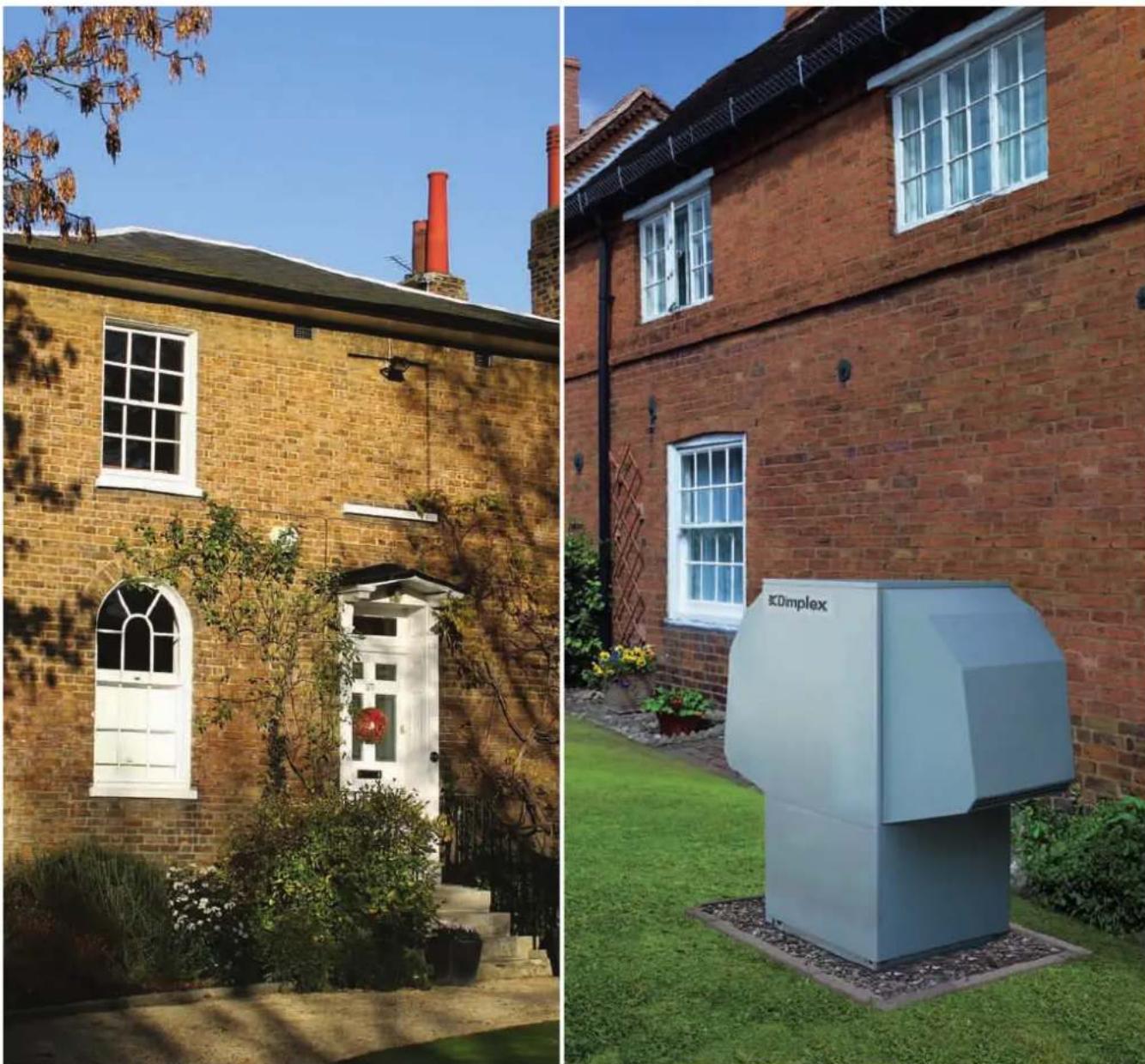
Domestic air source heat pumps
Dimplex domestic air source heat pumps are designed specifically for the UK climate and are constructed to withstand the best and worst of the British weather, with powder-coated metal casings and a stainless steel base frame. Installed outside the property, close to the building with a minimum 30cm clearance, they are ideal in situations where internal space is at a premium.
With low noise levels and outputs ranging from 8 to 16kW, the Dimplex domestic air source heat pump models provide a range of cost effective heating and hot water solutions for small to large properties.
Our domestic air source heat pumps are designed to deliver 100% of the heating and hot water demand, with the heat pump itself typically sized to provide at least 99% of the annual heating requirement. To minimise investment costs, it is normal to provide the remaining energy demand from a supplementary heat source, most commonly an electric immersion heater, however in retro-fit applications it is also possible to run the heat pump in parallel – “bivalent” mode – with an existing boiler.
natural_image
Side-by-side comparison of a brick building with a white door and chimney, and an industrial storage unit labeled 'EDimplex' in the courtyard (no signage on building itself)LA MS
Dimplex LA MS air source heat pumps provide excellent levels of heating and hot water performance at temperatures as low as -20^ , and can be used in place of or alongside an existing boiler to reduce energy bills and CO_2 emissions.
The range incorporates innovative design technologies to minimise sound transmissions and an auto-adaptive defrost cycle to minimise energy consumption.
natural_image
Exterior view of a large industrial air conditioning unit (no visible text or symbols)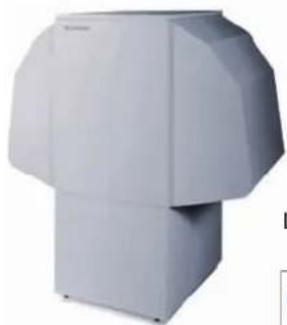
natural_image
Exterior view of a modern office building (no signage)LA 11/16 MS
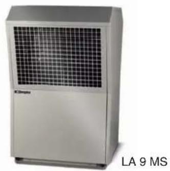
| Model | LA 9 MS | LA 11 MS | LA 16 MS |
| Connection Voltage (V) | 230 | 230 | 230 |
| Maximum flow temperature (°C) | 55 | 55 | 55 |
| Heat output A7/W35 (kW) | 9.5 | 10.9 | 15.1 |
| CoP A7/W35 | 3.9 | 3.9 | 3.6 |
| MCS certificated | √ | √ | √ |
Please see page 47 for full technical specifications.
LA PMS
Dimplex LA PMS high temperature air source heat pumps provide variable water flow temperatures of up to 65°C to provide a complete heating and hot water solution in place of or alongside an existing boiler.
The range uses R290, an efficient and naturally occurring refrigerant with close to zero GWP
natural_image
Exterior view of a modern office building (no signage)
| Model | LA 8 PMS | LA 14 PMS |
| Connection Voltage (V) | 230 | 230 |
| Maximum flow temperature (°C) | 65 | 65 |
| Heat Output A7/W35 (kW) | ||
| 1 compressor | 6 | 7.4 |
| 2 compressors | - | 13.3 |
| CoP A7/W35 | ||
| 1 compressor | 3.8 | 3.7 |
| 2 compressors | - | 3.9 |
| MCS certificated | √ | √ |
Please see page 47 for full technical specifications.
Range features
- 3 models with nominal heating capacities from 9 – 16kW single phase
• High levels of efficiency with CoPs of up to 3.9 - Variable heating water flow temperatures from 35 to 55°C with weather compensation
- Suitable for use with underfloor heating, Dimplex SmartRad or conventional radiators
- Ideal for use with a Dimplex EC-Eau heat pump-ready cylinder to produce domestic hot water
• Available in system packages with EC-Eau cylinders/buffer tanks and controls and ancillaries for ease of specification and installation - MCS certifi cated
Range features
- 2 models with nominal heating capacities from 8 – 14kW single phase
• High levels of efficiency with CoPs of up to 3.9 - Variable heating water flow temperatures from 35 to 65^ C with weather compensation
- Suitable for use with underfloor heating, Dimplex SmartRad or conventional radiators
- Ideal for use with a Dimplex EC-Eau heat pump-ready cylinder to produce domestic hot water
• Available in system packages with EC-Eau cylinders/buffer tanks and controls and ancillaries for ease of specification and installation
Commercial air source heat pumps
High efficiency air source heat pumps
Dimplex high efficiency air source heat pumps deliver maximum energy efficiency even at low ambient air temperatures to produce seasonal efficiencies comparable with ground source systems. With a range of high efficiency models ranging from 17 – 60kW, Dimplex can provide the solution to high capacity heating demands.
Optimised twin compressor operation ensures that buildings with high heat consumption requirements, such as offices, schools, hotels or retail units can be catered for. High efficiency heat pumps are also an ideal solution for multiple occupancy buildings such as apartment blocks where centralised heat pump systems are able to provide a building wide heating solution.
The LA TU range of air source heat pumps utilise the WPM EconPlus heat pump manager to monitor, regulate and control the entire heating system. Internally wall mounted, the heat pump manager can control up to three individually programmed heating circuits, any supplementary heating sources and the defrost cycle ensuring the LA TU operates flexibly and at maximum efficiency.
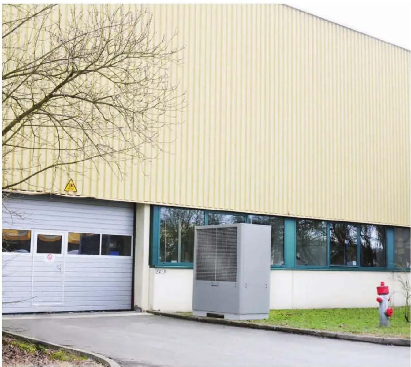
natural_image
Exterior view of a modern industrial building with a white storage unit and yellow corrugated facade, featuring a warning sign and a red fire hydrant (no readable text or symbols)
natural_image
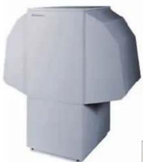
Exterior view of a large industrial air conditioning unit with grid-patterned panel (no visible text or symbols)LA 40 TU

LA TU
The Dimplex LA TU range of high efficiency air source heat pumps are designed to maximize energy efficiency at low ambient temperatures to deliver seasonal performances comparable to ground source systems. The high capacity outputs achievable with this range provide a flexible range of solutions for applications with higher capacity demands.
Twin compressor operation enables these models to flexibly and efficiently adapt to
fluctuating heat demand by automatically switching between single and dual compressor modes depending on the outside air temperature and the building's heating demand.
All models utilize the WPM EconPlus heat pump manager, allowing independent control over multiple heating circuits at differing flow temperatures and integrated heat metering.
| Model | LA 17 TU | LA 25 TU | LA 40 TU | LA 60 TU |
| Connection Voltage (V) | 400 | 400 | 400 | 400 |
| Maximum flow Temperature (°C) | 58 | 58 | 58 | 65 |
| Heat Output A7/W35 (kW) | ||||
| 1 compressor | 10.0 | 13.9 | 20.0 | 31.9 |
| 2 compressors | 19.6 | 26.1 | 35.7 | 60.1 |
| CoP A7/W35 | ||||
| 1 compressor | 4.5 | 4.5 | 4.6 | 4.3 |
| 2 compressors | 4.4 | 4.4 | 4.4 | 4.1 |
| MCS certificated | √ | √ | √ | N/A |
Please see page 48 for full technical specifications.
Range features
- Range of 4 models with nominal heating capacities from 17 – 60kW
- Variable heating water flow temperatures from 35°C to 58°C (65° LA 60 TU), weather compensated
- Intelligent load switching between single and dual compressor modes to maximise efficiency and compressor life
• Wall mounted WPM EconPlus heat pump manager with integrated heat meter
• Three phase connection, with electronic soft start to reduce start current loads - Optional flexible expansion for bivalent or bivalent-renewable operating mode and for distributed systems with mixed and unmixed heating circuits
- Suitable for use with underfloor heating, Dimplex SmartRad fan convectors or conventional radiators and to produce domestic hot water
• Sound optimised through electronically controlled, low-speed fan, with low, natural sounding acoustics - Side or under unit entry for hydraulic/electrical connections
- Multiple units can be connected in parallel
- MCS certificated
Commercial air source heat pumps
High output and high temperature air source heat pumps
The Dimplex range of high output air source heat pumps are ideal for multiple occupancy properties such as flats and apartments when installed as a centralised heat pump system. With models ranging from 20-28kW our high output air source heat pumps are able to provide an efficient, building-wide heating solution.
Employing optimised twin compressor operation this high output range can also cater for buildings with high heat consumption such as offices, schools, hotels or retail outlets.
Improving a buildings thermal insulation can often be enough to allow the heating system to be operated at the low temperatures normally associated with heat pumps. However higher water flow temperatures are sometimes needed where high volumes of hot water are required at temperatures of 60^ C or higher, or where the heat pump is intended for use in older buildings with existing radiator systems.
The Dimplex range of high temperature air source heat pumps can easily fulfil these requirements by providing variable water flow temperatures of up to 65°C.
Parallel operation for higher total capacity
Multiple Dimplex heat pumps can be connected together in parallel to provide a highly cost effective solution where very high capabilities are required. The WPM heat pump manager controls and optimises performance of the system.

text_image
SUBWAY Travelodge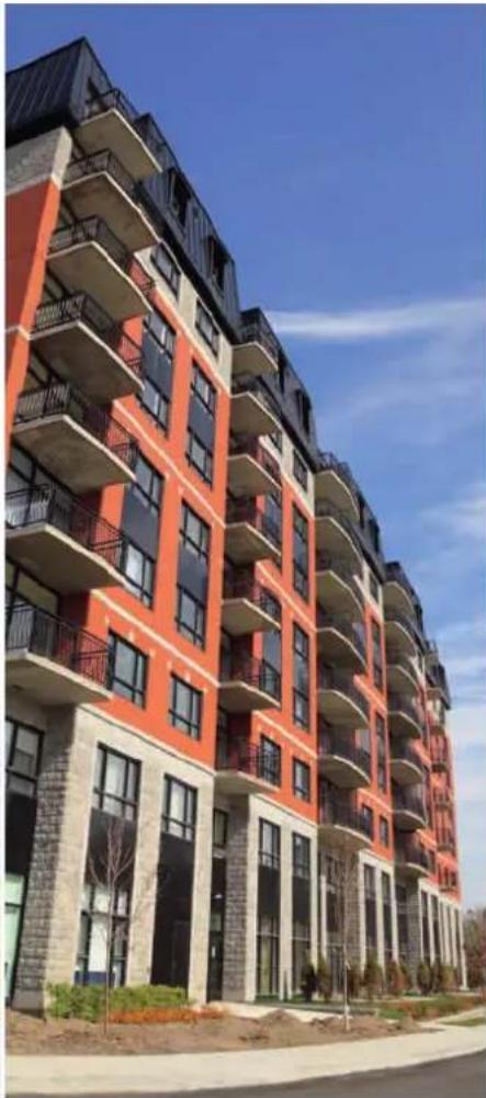
natural_image
Exterior view of a modern multi-story residential building with red and black facade, balconies, and windows under a clear blue sky (no signage or text visible)High output air source heat pumps – LA AS
The Dimplex LA AS range of high output 3 phase air source heat pumps provide a flexible range of solutions for higher capacity heating systems.
Twin compressor operation enables these models to efficiently adapt to fluctuating heat demand by automatically switching between single and dual compressor modes depending on outside temperature and building heat demand.
natural_image
Exterior view of a modern office building (no signage)LA 20-28 AS
| Model | LA 20 AS | LA 24 AS | LA 28 AS |
| Connection Voltage (V) | 400 | 400 | 400 |
| Maximum flow temperature (°C) | 55 | 55 | 55 |
| Heat output A7/W35 (kW) | |||
| 1 compressor | 9.8 | 13.1 | 14.2 |
| 2 compressors | 16.6 | 24.8 | 25.8 |
| CoP A7/W35 | |||
| 1 compressor | 3.2 | 3.4 | 3.1 |
| 2 compressors | 3.1 | 3.6 | 3.4 |
Please see page 49 for full technical specifications.
High temperature air source heat pumps – LA PS
The LA PS high temperature range of air source heat pumps provide variable water flow temperatures of up to 65°C and utilise the environmentally sensitive R290 refrigerant.

natural_image
Exterior view of a modern office building (no signage)
| Model | LA 17 PS | LA 22 PS | LA 26 PS |
| Connection Voltage (V) | 400 | 400 | 400 |
| Maximum flow temperature (°C) | 65 | 65 | 65 |
| Heat output A7/W35 (kW) | |||
| 1 compressor | 9.6 | 12.0 | 13.3 |
| 2 compressors | 16.6 | 21.1 | 22.9 |
| CoP A7/W35 | |||
| 1 compressor | 3.4 | 3.6 | 3.5 |
| 2 compressors | 3.4 | 3.5 | 3.5 |
| MCS certificated | √ | - | - |
Please see page 50 for full technical specifications.
Range features
- 3 models with nominal heating capacities from 20 – 28kW
- Variable heating water flow temperature from 35°C to 55°C with weather compensation
• WPM 2007 heat pump manager
• Electronic soft start to reduce current loads - Suitable for use with underfloor heating, Dimplex SmartRad or conventional radiators and to provide hot water
Range features
- 3 models with nominal heating capacities from 17 – 26kW
- Variable heating water flow temperature from 35°C to 65°C with weather compensation
- Intelligent switching between single and dual compressor modes, maximising efficiency and compressor duty cycle
• WPM 2006 heat pump manager
• Electronic soft start to reduce current loads
• Utilises environmentally sensitive R290 refrigerant - Suitable for use with underfloor heating, Dimplex SmartRad or conventional radiators and to provide hot water
Ground source heat pumps
Drawing as much as 75% of the energy needed by the heating system from freely available, inexhaustible solar energy stored in the ground, Dimplex ground source heat pumps are available in an extensive range of models types and capacities suitable for either domestic or commercial applications.
Due to highly stable temperatures below the earth's surface, ground source heat pumps provide high levels of efficiency for space and water heating all year round.

natural_image
A couple relaxing on a grassy hillside, one adult and one child, both smiling (no text or symbols visible)Benefits of the ground as a heat source
- Consistent temperatures below ground throughout the year provides a high Co-efficient of Performance.
- Can be used for heating, domestic hot water and swimming pools.
- Borehole systems can be used for either passive or active cooling (see page 33).
At just 1m below the surface, the earth provides a stable source of heat throughout the year.
At depths of 15m or more, the earth provides a constant 10^ C temperature.
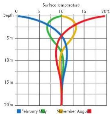
line
| Depth (m) | February May | November August | Other | | --------- | ------------ | --------------- | ----- | | 0 | 0 | 0 | 0 | | 5 | 0 | 0 | 0 | | 10 | 0 | 0 | 0 | | 15 | 0 | 0 | 0 | | 20 | 0 | 0 | 0 |Installation
The earth stores an enormous amount of solar energy from both solar radiation and rainfall. To extract this energy, ground collectors consisting of flexible poly ethylene pipes are buried in the earth, either horizontally or vertically. A mixture of water and anti-freeze is then circulated through the pipe loops, attracting the heat energy and transferring it to the heat pump.
Horizontal ground collectors
If a large enough land area is available, horizontal ground collectors provide an effective method of extracting heat from the ground.
The pipework is buried at a depth of approximately 1.2m and spaced 0.75m apart. The land area required is
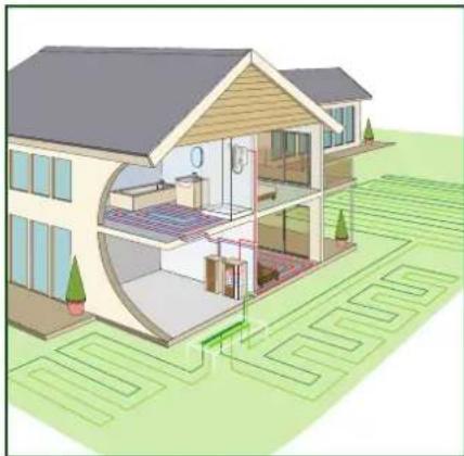
natural_image
Architectural rendering of a two-story residential house with curved roof and adjacent courtyard (no text or symbols)dependent on both the capacity of the heat pump and heat conductance of the soil type in which the pipes are buried.
As a space saving alternative to horizontal collectors, slinkies, consisting of coiled pipes buried in a trench can be used.
Vertical boreholes
If land space is limited the ground collectors can be installed vertically in a borehole, drilled up to 100m deep in the ground.
Multiple boreholes are commonly used in large installations where very high levels of heat extraction are required.

natural_image
Architectural cutaway diagram of a two-story house showing interior layout and outdoor seating (no text or labels)Case studies
Heat pumps in action
Dimplex heat pumps have been installed in a wide variety of applications – two are featured here, but more are available on our website.
Housing Association bungalows convert to Dimplex
Stafford & Rural housing association has fitted Dimplex ground source heat
pumps into a refurbishment project of nine warden-linked bungalows at Synnerton, Staffordshire, with five of the properties taking part in a year long survey by the EST to monitor heat pumps in real-life installations.
One of the key considerations when replacing the system was fuel poverty as economic heating was very important to its tenants. The housing association was also looking for something that was future-proof, cost effective with no costly bills or annual inspections. Three suppliers were considered by an assessment panel which included 3 tenants with Dimplex selected because of the overall package they could supply.
natural_image
Exterior view of a brick house with a chimney and surrounding greenery (no signage or text visible)Top Marks for Dimplex in London school
Ealing council has installed Dimplex ground source heat pumps at three schools and is already planning a fourth!

natural_image
Exterior view of a two-story brick building with windows and a wooden fence in front (no signage or text visible)A Dimplex SIH 40 TE high temperature ground source heat pump was initially installed at Grange Primary School, a larger than average school with 500 pupils, with 15 boreholes required in a restricted area which subsequently became part of the playground.
Following the success at Grange Primary, a Dimplex SI 37 TE heat pump has been installed at Mandeville School, Northolt, a co-educational day school for pupils aged 2-12 and a SI 24 TE has been installed at Ellen Wilkinson School for Girls in Acton, with 1400 students aged 11-18.
Domestic ground source heat pumps
Dimplex domestic ground source heat pumps are available in a range of sizes and configurations to provide a sustainable, cost effective heating and hot water solution for most domestic applications.
Ideal for use with either underfloor heating, SmartRad or conventional radiator systems Dimplex domestic ground source heat pumps are also able to provide domestic hot water.
The range includes high temperature models which can produce water flow temperatures up to 70^ C, providing the ability to fulfil all of the hot water demands of the property without the need for supplementary electric heating.
Installed inside the property, the range is available in outputs from 4 –16kW in either standalone or integrated formats providing maximum flexibility to meet the installation requirements of virtually any domestic scenario.
natural_image
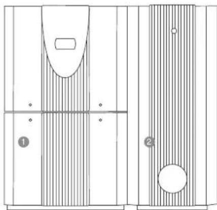
Side-by-side comparison of a brick house with solar panels on the left and a modern brick courtyard at dusk on the right (no visible text or symbols)Flexible system options
The Dimplex ground source range, including buffer tanks and hot water cylinders are designed to fully co-ordinate and provide a range of flexible system options:
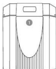
1 SIH ME/SI ME ground source heat pump
② SIK ME integrated ground source heat pump
3 WWSP229EUK 200L domestic hot water cylinder
4 PSP100E 100L buffer cylinder
5 WWSP442EUK 400L domestic hot water cylinder
natural_image
Line drawing of a mechanical device with a central oval component and side panels (no text or symbols)
natural_image
Technical line drawing of a mechanical component with four labeled parts (1, 3, 4), no readable text or symbols present.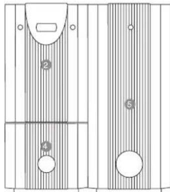
text_image
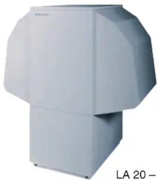
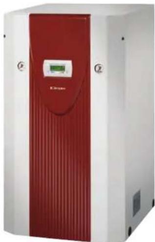
2 4 5High temperature ground source heat pumps – SIH ME
The SIH ME range provides flow temperatures up to 70°C enabling 100% of a home's heating and hot water to be provided without the need for supplementary heating.
Domestic ground source heat pump – SI 14 ME
Identical in design to the SIH ME range, the popular SI 14 ME provides flow temperatures up to 58°C making it an ideal domestic heating solution.
Where space saving is an issue the SIH ME and SI ME can be combined with a 200L domestic hot water cylinder, which fits neatly below the heat pump unit.

natural_image
Exterior view of a red and white industrial device labeled 'E-Clappe' (no additional text or symbols visible)
SIH ME/SI ME
| Model | SIH 4 ME | SIH 6 ME | SIH 9 ME | SIH 11 ME | SI 14 ME |
| Connection Voltage (V) | 230 | 230 | 230 | 230 | 230 |
| Maximum flow temperature (°C) | 70 | 70 | 70 | 70 | 58 |
| Heat output B0/W35 (kW) | 4.0 | 6.0 | 8.9 | 10.7 | 14.8 |
| CoP B0/W35 | 4.1 | 4.1 | 4.0 | 4.5 | 3.9 |
| MCS certificated | √ | √ | √ | √ | √ |
Please see page 51 for full technical specifications.
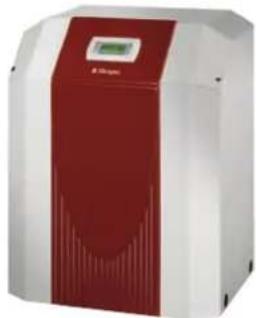
Integrated ground source heat pump – SIK ME
The SIK 16 ME fully integrated ground source heat pump provides easy installation and minimises space requirements, with the heat pump manager and key system components all fully integrated into one compact unit.
A complementary 100L buffer tank and 400L domestic hot water cylinder are also available to complete the system.

SIK 16 ME
natural_image
Exterior view of a red and white industrial machine with control panel (no visible text or symbols)| Model | SIK 16 ME |
| Connection Voltage (V) | 230 |
| Maximum flow temperature (°C) | 58 |
| Heat output B0/W35 (kW) | 15.8 |
| CoP B0/W35 | 4.2 |
| MCS certificated | √ |
Please see page 52 for full technical specifications.
Range features
- 4 high temperature models with nominal heating capabilities from 4 – 11kW
• 1 standard temperature model with nominal heating capabilities of 14 kW - Variable heating water flow temperatures from 35°C to 70°C with weather compensation (high temperature models)
• WPM 2007 heat pump manager with removable control panel
• Electronic soft start control reduces starting current loads - Suitable for use with underfloor heating, Dimplex SmartRad fan convectors or conventional radiator systems and to produce domestic hot water
- Can be used as the sole heating source or in "bivalent" mode in combination with an existing heating system
- Provides domestic hot water to 60°C with no need for supplementary heating (high temperature models)
Range features
• Available with nominal heating capacities of 16kW
- Integrated system components, including circulating pumps, expansion vessels and safety assemblies for both the heating and ground collector circuits
• WPM2007 heat pump manager with removable control panel
- Variable heating water flow temperatures from 35°C to 55°C with weather compensation
- Suitable for use with underfloor heating, Dimplex SmartRad fan convectors or conventional radiator systems and to produce domestic hot water
- Matching built-under buffer tank for space
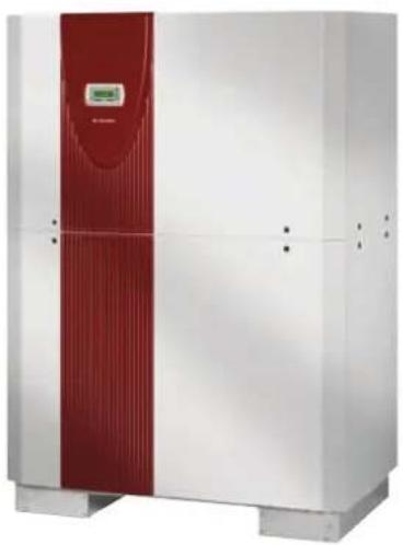
Commercial ground source heat pumps
High output ground source heat pumps
Dimplex high output ground source heat pumps expand the scope of applications for high efficiency heating solutions with ranges of increased output models ranging from 18 – 130kW.
Optimised twin compressor operation allows buildings with high heat consumption to be catered for, in the shape of either non-domestic applications such as offices or schools. High output heat pumps are also ideal for multiple occupancy buildings such as flats and apartments where centralised heat pump systems are able to provide a building wide heating solution.

natural_image
Exterior views of a modern building with glass facade and adjacent historic clock tower (no signage)Flexible system options
SI 24 TE – SI 37 TE heat pumps are designed to co-ordinate with the WWSP442EUK hot water cylinder.
natural_image
Technical line drawing of two mechanical components with internal features and mounting holes (no text or symbols)① SI 24-37 TE ground source heat pump ② WWSP442EUK 400L hot water cylinder
High output ground source heat pumps – SI TE/ SI TU
The Dimplex SI TE and SI TU ranges of high output 3 phase ground source heat pumps provide a flexible range of solutions for higher capacity heating systems.
All models utilise the WPM2007 heat pump manager, allowing independent control over multiple heating circuits at differing flow temperatures.
Models with outputs of 24kW and above incorporate twin compressors, enabling them to flexibly and efficiently adapt to fluctuating heat demand by automatically switching between single and dual compressor modes depending on the outside temperature and heat demand of the building.
natural_image
Exterior view of a white industrial machine with red vertical panel and digital display (no visible text or symbols)SI 50-130 TE
natural_image
Exterior view of a red and white industrial device with a digital display (no visible text or symbols)SI 18-22 TU

natural_image
Exterior view of a modern industrial machine with red and white panels (no visible text or symbols)SI 24-37 TE
Range features
- Range of 9 models with nominal heating capacities from 18 – 130kW
- Variable heating water flow temperatures from 35°C to 60°C with weather compensation
- Twin compressors on outputs of 24kW and over for higher capacity output
- Intelligent switching between single and dual compressor modes, maximising efficiency and compressor duty cycle
• WPM2007 heat pump manager with removable control panel - Suitable for use with underfloor heating, Dimplex SmartRad fan convectors or conventional radiator systems and to produce domestic hot water
- Three phase electrical connection, with electronic soft start to reduce start current loads
- Able to use ground water as a heat source with the addition of an intermediate heat exchanger
- Matching 400 litre domestic hot water cylinder

| Model | SI 18 TU | SI 22 TU | SI 24 TE | SI 30 TE | SI 37 TE | SI 50 TE | SI 75 TE | SI 100 TE | SI 130 TE |
| Connection Voltage (V) | 400 | 400 | 400 | 400 | 400 | 400 | 400 | 400 | 400 |
| Maximum flow temperature (°C) | 62 | 57 | 60 | 60 | 60 | 60 | 60 | 60 | 60 |
| Heat output B0/W35 (kW) | |||||||||
| 1 compressor | 17.5 | 22.9 | 12.7 | 14.4 | 18.3 | 23.0 | 37.6 | 48.4 | 63.3 |
| 2 compressors | - | - | 23.7 | 31.2 | 35.4 | 46.7 | 75.2 | 96.3 | 125.8 |
| CoP B0/W35 | |||||||||
| 1 compressor | 4.7 | 4.4 | 4.3 | 4.2 | 4.5 | 4.4 | 4.3 | 4.6 | 4.2 |
| 2 compressors | - | - | 4.1 | 4.6 | 4.3 | 4.5 | 4.4 | 4.6 | 4.3 |
| MCS certificated | √ | √ | √ | √ | √ |
Please see page 52-55 for full technical specifications.
Commercial ground source heat pumps
High temperature ground source heat pumps
Dimplex high temperature ground source heat pumps have the ability to provide high water flow temperatures of up to 70°C.
This makes them ideal for applications where high volumes of stored hot water are required at temperatures of 60^ C or higher, or where the heat pump is required to be connected to a high temperature heating system using radiators.
Optimised twin compressor operation allows the SIH TE range to be used in buildings with high heat consumption, for example commercial applications, schools or for centralised heat production in multiple occupancy residential buildings such as flats.
natural_image
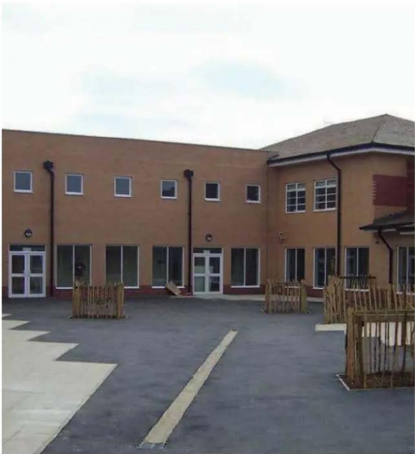
Exterior view of a two-story building with windows and a paved courtyard, featuring a wooden fence and partial signage (no readable text)
natural_image
Exterior view of a modern multi-story residential building with orange and gray facade, featuring balconies and windows under a clear blue sky (no signage or text visible)Flexible system options
SIH 20 TE is designed to co-ordinate with the WWSP442EUK hot water cylinder.
natural_image
Technical line drawing of a mechanical component with vertical and horizontal sections (no text or symbols)1 SIH 20 TE ground source heat pump
2 WWSP442EUK 400L hot water cylinder
High temperature ground source heat pumps – SIH TE
The Dimplex SIH TE range of high temperature ground source heat pumps provide variable water flow temperatures up to 70°C, providing a solution for buildings with high temperature heating systems (radiators) or where high temperature hot water storage is required.
Available in 20kW and 40kW options, both models utilise the WPM2007 heat pump manager, allowing independent control over multiple heating circuits at differing flow temperatures.
Both models incorporate twin compressors, enabling them to flexibly and efficiently adapt to fluctuating heat demand by automatically switching between single and dual compressor modes depending on the outside temperature and heat demand of the building.

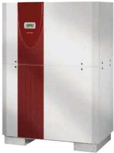
natural_image
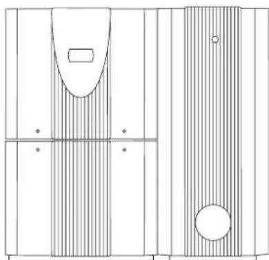
Exterior view of a modern industrial control unit with red and white panels (no visible text or symbols)SIH 20 TE
natural_image
Exterior view of a large industrial machine with red and white panels, no visible text or symbolsSIH 40 TE
| Model | SIH 20 TE | SIH 40 TE |
| Connection Voltage (V) | 400 | 400 |
| Maximum flow temperature (°C) | 70 | 70 |
| Heat output B0/W35 (kW) | ||
| 1 compressor | 11.5 | 17.4 |
| 2 compressors | 21.4 | 34.2 |
| CoP B0/W35 | ||
| 1 compressor | 4.6 | 4.1 |
| 2 compressors | 4.4 | 4.1 |
| MCS certificated | √ | √ |
Please see page 54 for full technical specifications.
Range features
• 2 high temperature models with nominal heating capacities of 20kW and 40kW
- Variable heating water flow temperatures from 35°C to 70°C with weather compensation
- Twin compressors for higher capacity output
- Intelligent switching between single and dual compressor modes, maximising efficiency and compressor duty cycle
• WPM2007 heat pump manager with removable control panel
- Suitable for use with underfloor heating, Dimplex SmartRad fan convectors or conventional radiator systems and to provide domestic hot water at stored water temperatures of up to 60°C
- Three phase electrical connection, with electronic soft start to reduce start current loads
- Able to use ground water as a heat source with the addition of an intermediate heat exchanger
- Matching 400 litre domestic hot water cylinder
Reversible heat pumps
Innovative heating and cooling
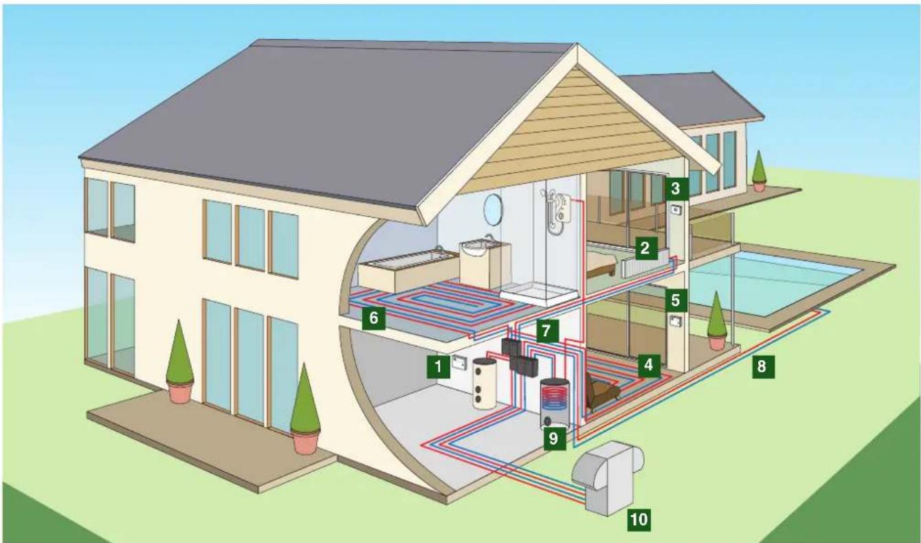
Apart from an efficient heat pump heating system, summer time cooling of well-insulated new buildings is becoming increasingly important to achieve a comfortable environment. Solar gain, higher levels of insulation and increasingly warm summer temperatures all lead to a rising demand for cooling systems. Dimplex offers an innovative, energy efficient concept for all types of heat sources to also utilise water-bearing heating systems for cooling purposes.
text_image
Diagram of a household water heating system with numbered components for spatial reference1 Heat pump manager for heating and cooling
2 Dynamic cooling via fan convectors with condensate drainage; suitable for domestic buildings with high heat loads and commercial buildings
3 Room thermostats switch from heating to cooling via an external signal from the cooling controller
4 Silent cooling utilising existing heating surfaces (underfloor, ceiling or wall cooling)
5 Room climate control station for regulating the flow temperature with silent cooling via a reference room
6 Underfloor heating for comfortable heat in the winter
7 Dew point monitor for connection to the cooling controller to interrupt the cooling operation of the system if condensate forms at vulnerable points in the cooling distribution system
8 The waste heat produced in cooling operation can be utilised for swimming pool water heating
9 Efficient domestic hot water preparation utilising waste heat recovery in cooling operation
10 Reversible air source heat pumps for outdoor installation
Reversible air source heat pumps
Models available:
35kW three phase with waste heat recovery (LA 35 TUR+)
60kW three phase with waste heat recovery (LA 60 TUR+)
LA 35 TUR+
LA 60 TUR+
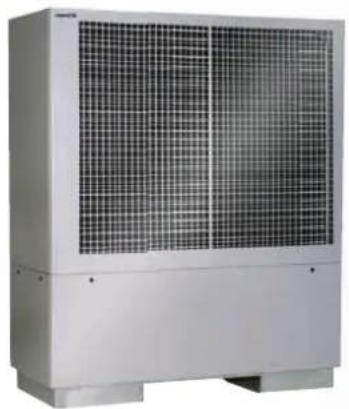
natural_image
Exterior view of a large industrial air conditioning unit with grid-patterned panels (no visible text or symbols)
natural_image
Black-and-white photo of a smiling man holding a green globe with Africa map silhouette (no text or symbols)Reversible heat pumps for active cooling
In winter the heat pump functions as an energy efficient heating device and extracts the required energy from the environment. By reversing this process the heat pump can be operated to provide cooling, extracting heat from the building and transferring this to the environment via the heat pump refrigerant and compressor.
Waste heat recovery makes it possible to also produce domestic hot water extremely efficiently during the cooling process, while returning waste heat to the ground (using a ground source heat pump) effectively stores the energy for use later in the year when needed for heating.
The entire system is controlled by the heat pump manager.
Passive cooling with borehole heat exchangers or ground water.
Deeper ground layers have constant temperature levels of around 10^ C all year round. This allows ground source heat pumps installed with vertical borehole collectors to be used to provide 'passive' cooling, by transferring excess heat from the building to the ground via the collector in the summer months.
This is achieved with the addition of a retro-fi ttable passive cooling unit, controlled by an additional cooling controller, which communicates with the heat pump manager to enable a combination of heating and 'comfort' cooling in a single system.
Domestic hot water can still be provided in parallel to the cooling operation as the heat pump compressor is not active in the passive cooling mode.
Depending on the type of heating system installed in the building, cooling can be provided in one of two ways:
Silent (active) cooling via surface heating systems
In summer, the heating surfaces in floors, walls and ceilings are activated for cooling by passing cooled water through them. Large cooled surfaces cool the rooms to a comfortable temperature without draughts or air movement.
Dynamic cooling via fan convectors
Integrated ventilators guide the indoor air to a heat exchanger, which heats or cools the air according to need. Multi-level controllable air recirculation guarantees short response times and high transmission capacities.
Reversible ground source heat pumps
Models available:
30kW three phase with waste heat recovery (SI 30 TER+)
75kW three phase with waste heat recovery (SI 75 TER+)
130kW three phase with waste heat recovery (SI 130 TUR+)

natural_image
Exterior view of a modern industrial control unit with red and white panels (no visible text or symbols)SI 75 TER+ SI 130 TUR+
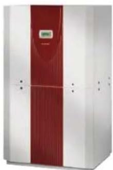
natural_image
Exterior view of a modern industrial machine with red vertical panel and white walls (no visible text or symbols)SI 30 TER+
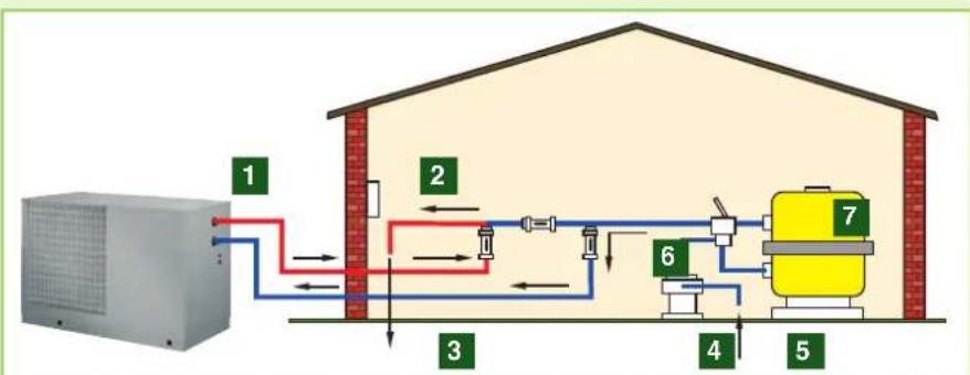
Swimming pool heat pumps
Heat pumps are the ideal solution for swimming pool heating, providing an economic and energy efficient means of delivering a constant pool water temperature throughout the year. Air source heat pumps are particularly suitable due to their low installation cost and high efficiency at high ambient temperatures during the summer – the most frequent time of swimming pool use!

natural_image
Swimmer performing a dive into a pool with water splashing (no text or symbols visible)1 Swimming pool heat pump
2 Remote control
3 Pure water to the pool
4 Circulating pump
5 Bypass and regulator valves
6 Pipe water from the pool
7 Filter
flowchart
graph TD
    A["HVAC"] --> B["1"]
    B --> C["2"]
    C --> D["3"]
    D --> E["4"]
    E --> F["5"]
    F --> G["6"]
    G --> H["7"]
    style A fill:#f9f,stroke:#333
    style H fill:#bbf,stroke:#333
The heat pump is connected directly to the pool system. No additional control.
Swimming pool heat pumps – air source – LAS MT & LASTT
Dimplex LAS MT and LAS TT air source heat pumps provide an energy efficient and cost effective way of providing swimming pool heating throughout the year, irrespective of the weather conditions.
Purpose designed for swimming pool use and incorporating a titanium heat exchanger which allows the heat pump to be used with varying levels of water quality, the range is available in outputs from 10 – 22kW. The heat pump is installed outdoors and integrated into the swimming pool filter circuit.
A single heat pump setting ensures the required swimming pool water temperature is constantly maintained.
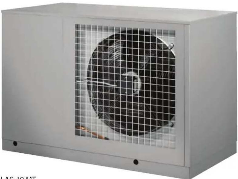
natural_image
Exterior view of a white industrial fan unit with a mesh grille (no text or symbols visible)LAS 10 MT
| Model LAS 10 MT | LAS 15 MT | LAS 22 MT | |
| Connection Voltage (V) | 230 | 230 | 400 |
| Maximum flow temperature (°C) | 40 | 40 | 40 |
| Heat output A20/W24 (kW) | 12.1 | 16.6 | 22.3 |
| CoP A20/W24 | 4.2 | 4.7 | 5.1 |
Please see page 55 for full technical specifications.
Range features
• Outdoor installation
• Nominal heating capacities of 10kW, 15kW and 22kW
- Variable heating water flow temperatures up to 40°C
• WPM2007 heat pump manager with removable control panel
• Titanium heat exchanger ensuring safe operation with variable water qualities, including salt water
- Integrated automatic defrost cycle, allowing operation at temperatures as low as -10^
Heat pump accessories
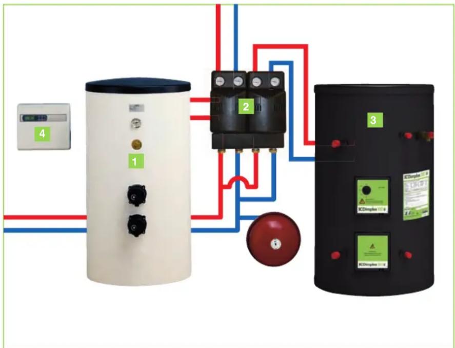
Perfectly matched
Dimplex heat pumps offer a variety of services – providing the home with comfortable warmth is only one of them. It can also provide all the hot water needed for the kitchen and bathroom.
Dimplex provides all the components needed for these applications, including buffer tanks, EC-Eau unvented hot water cylinders, hydraulic accessories and SmartRad fan convectors, ensuring the components are optimally matched to ensure maximum system efficiency.
A range of ancillary products designed to simplify heating system and ground collector connections are also available, ensuring installation is as compact and simple as possible.
1 Buffer Tank
2 Heating/DHW System Connection
3 EC-Eau Unvented Hot Water Cylinder
4 WPM Heat Pump Manager
text_image
Diagram of a thermal power plant system with labeled components including a control panel, two electrical relays, and a battery.Buffer tanks
Connection of a buffer tank ensures minimum compressor run times and minimum water flow rates through the heat pump to maintain optimum efficiency. A buffer is essential for air source heat pumps as it provides the energy for defrosting.
Where the heat pump provides the sole source of heating, an electric immersion element can also be integrated to provide supplementary heating if required.
| Model | Capacity (litres) | Dimensions (mm) | For use with |
| PSW100 | 100 | 512 × 850 | Heat pumps up to 12kW |
| PSP100E | 100 | 740x740x240 | SI ME & SIK ME models |
| PSW200 | 200 | 600 × 1300 | Heat pumps up to 30kW |
| PSW500 | 500 | 700 × 1950 | All heat pumps |
| PSW1000 | 1000 | 790 × 1970 | All heat pumps |

natural_image
White cylindrical water heater with black buttons and a digital display (no visible text or symbols)Note: a suitably sized immersion element must be ordered separately
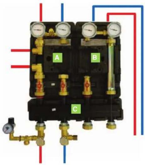
Distribution system
Modules matching the specific requirements of the heat pumps simplify connection to the heating system and offer the option of flexible expansion for domestic hot water or additional heating circuits.
Most common components are;
A Compact manifold (KPV25) allows connection between heat pump, buffer tank and a single heating circuit, simplifying the installation process and reducing space
B Hot water module (WMM25) allows connection between the heat pump and the hot water cylinder
C Manifold bar (VTB25) allows simultaneous connection of the compact manifold and hot water module
D Dual differential pressureless manifold (DDV25/32) allows efficient connection between heat pump, buffer tank and heating circuit to simplify installation
| Model Flow rates (m ^3 /h) | ||
| KPV25 | up to 1.3m ^3 /h | Compact manifold |
| EBKPV | up to 2.0m ^3 /h | Extension module for KPV module |
| DDV25 | up to 2.0m ^3 /h | Dual differ. Pressure less module |
| DDV32 | up to 2.5m ^3 /h | Dual differ. Pressure less module |
| WWM25 | up to 2.5m ^3 /h | Heating circuit / hot water module |
| MMH25 | up to 2.0m ^3 /h | Mixed heating circuit module |
| VTB25 | up to 2.5m ^3 /h | Manifold bar |
| Additional manifolds for alternative systems | ||
| MMB25 | Flow rates up to 2.0m ^3 /h | Bivalent mixing manifold |
| SST25 | Max. of 10m ^2 solar panels | Solar station |
NOTE: Circulation pumps supplied separately in order to cater for differing flow rates (project specific).
text_image
A B C
natural_image
Two identical gas pressure gauges (D and B) mounted on a black base with blue and red flow lines indicating circulation or circulation paths (no text or symbols present)Commercial cylinders
For applications with a high hot water demand such as hotels, care homes and other multiple occupancy properties, Dimplex offers a range of commercial unvented hot water cylinders – all correctly sized for the maximum heating capacity of the heat pump.
It is important to remember that due to lower flow temperatures, correctly sized heat exchangers are required to maximise performance. An integrated temperature sensor is connected to the heat pump manager which allows the heat pump to automatically manage the production of hot water, ensuring a plentiful supply of hot water when required.
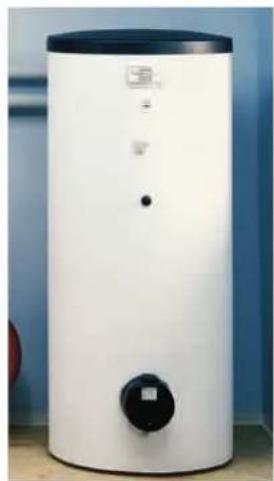
natural_image
White cylindrical water heater with black control knob and indicator lights, placed against a blue background (no visible text or symbols)All Dimplex heat pump cylinders are fully UK approved for G3 building regulations.

| Model | Capacity (litres) | Dimensions (mm) |
| WWSP880UK | 400 | 700 × 1600 |
| WWSP900Uk | 500 | 700 × 1950 |
EC-Eau™
heat pump cylinders
Dimplex EC-Eau heat pump cylinders are designed to operate seamlessly with heat pumps to provide an efficient and environmentally friendly way of supplying domestic hot water.
Employing a large surface area heat exchanger, EC-Eau heat pump cylinders maximise the transfer of renewable energy to the stored water, optimising heat pump efficiency and reducing running costs. EC-Eau heat pump cylinders are the ideal partner to Dimplex heat pumps and are available in capacities from 125 to 300 litres, suitable for most domestic hot water demands. Combined heat pump cylinder and buffer tanks models are also available for applications where space is limited.
Heat pump cylinders
| Model | Height (mm) | Diameter (mm) | Capacity (l) | Weight empty (kg) | Number of immersions | Expansion vessel (l) | Heat pump coil size (kW) | Heat pump coil surface area ( m^2 ) | Reheat Time (mins) | Heat loss in 24 hrs (kW/24hrs) |
| ECS125HP-580 | 960 | 580 | 125 | 30 | 1 | 12 | 45(*) | 2.2 | 7(*) | 0.95 |
| ECS150HP-580 | 1130 | 580 | 150 | 35 | 1 | 12 | 51(*) | 2.8 | 7(*) | 1.10 |
| ECS175HP-580 | 1280 | 580 | 175 | 37.5 | 1 | 19 | 43.3(*) | 2.8 | 11(*) | 1.12 |
| ECS210HP-580 | 1505 | 580 | 210 | 42 | 1 | 19 | 47(*) | 3.0 | 12(*) | 1.41 |
| ECS250HP-580 | 1780 | 580 | 250 | 47 | 1 | 24 | 47(*) | 3.0 | 17(*) | 1.51 |
| ECS300HP-580 | 2080 | 580 | 300 | 53 | 1 | 24 | 43(*) | 3.2 | 20(*) | 1.96 |

natural_image
Exterior view of multiple black cylindrical tanks with green labels and red connectors (no readable text or symbols)Heat pump cylinder range
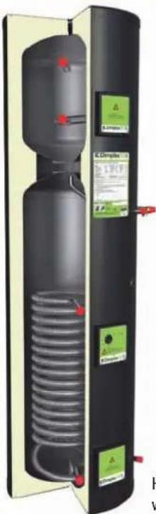
natural_image
Exterior view of a black industrial water heater unit with coiled tubing and control panel (no visible text or symbols)Heat pump cylinder with buffer
Heat pump cylinders with buffer
| Model | Height (mm) | Diameter (mm) | Capacity (l) | Buffer capacity (l) | Weight empty (kg) | Number of immersions | Expansion vessel (l) | Heat pump coil size (kW) | Heat pump coil surface area ( m^2 ) | Reheat Time (mins) | Heat loss in 24 hrs (kW/24hrs) |
| ECS125HP75-580 | 1535 | 580 | 125 | 72 | 44.5 | 2 | 12 | 45(*) | 2.2 | 7(*) | 0.95 |
| ECS150HP75-580 | 1705 | 580 | 150 | 72 | 49 | 2 | 12 | 51(*) | 2.8 | 7(*) | 1.10 |
| ECS210HP75 | 2080 | 580 | 210 | 72 | 57 | 2 | 19 | 47(*) | 3.0 | 12(*) | 1.41 |
*Determined in accordance with EW12897-2000
Unvented stainless steel cylinders for heat pumps
Sustainable Material
• Inner vessel manufactured from premium grade Duplex stainless steel
• Lightweight yet ultra high strength and stress/corrosion resistant, ensuring long cylinder life
• 100% recyclable
• No need for sacrificial anode
• 25 year warranty
• HIPS/ABS outer cladding
• Produced from 100% recycled material
• Hard wearing, fl exible and damage resistant
• CFC/HCFC free injected foam insulation
• High proportion of materials (excluding insulation) by volume recycled
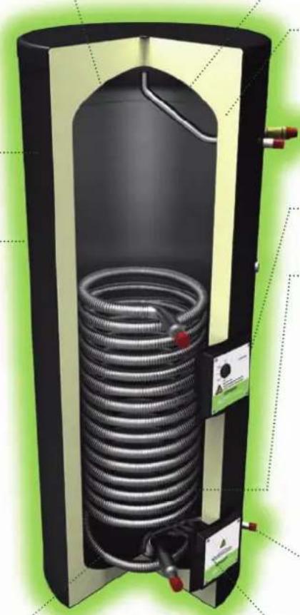
natural_image
3D rendering of a vertical cylindrical heating element with coiled tubing and heat exchanger (no text or symbols visible)Environmentally Sound Performance
- Designed for use with renewable sources of heat production – heat pumps and solar thermal systems
- Side hot water draw off connection, minimises heat losses through the top of the cylinder
60mm of injected polyurethane foam insulation
- Exceeds 'CHESS' best practice standards for low heat loss and heat recovery
• Completely void free, including insulation around immersions and thermostats
Recessed immersion heater and thermostat housings reduces heat loss
Large surface area coil for use with heat pumps
Superior Operational Performance
- High flow rates for efficient hot water delivery
• Powerful showers and fast fi lling baths
• Corrugated coil construction maximises surface area while maintaining high usable volume
• Light and easy to handle for easy installation
• Surface mounted thermostats and sensors for easy installation and maintenance/replacement
• Supplied complete with inlet safety group and external expansion vessel
• All connections accessible from the front
Heat pump
manager
Everything is under control
The majority of Dimplex heat pumps utilise the WPM heat pump manager, which is designed to regulate, control and monitor the entire heating system.
Water temperatures for up to 3 heating / hot water circuits are individually programmable, allowing the heat pump to provide maximum flexibility, control and efficiency.

natural_image
Illustration of a hand holding a green globe, symbolizing global ecological achievement (no text or symbols)Key features:
• Simple 6 key operation
• Large, well laid out illuminated display
- Dynamic menu based programming, customised to the configuration of the heat pump – settings that are not required are hidden
• Interface for remote control unit with identical menu options
• Ground source and indoor air source units have removable control panel for convenient positioning
• Weather compensated temperature control
• Control over 3 separate heating/hot water circuits
• Automatic actuation of supplementary heat source (electric immersion heater or gas/oil boiler)
- Automatic actuation of mixer valves for supplementary heat generators (gas/oil boiler or solar energy storage system)
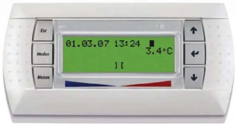
text_image
01.03.07 13:24 3.4°C ][
text_image
01.03.07 13:24 3.4°C ][Two heat generators and three heat consumers; the heat pump has everything under control
The heat pump manager monitors the operation of the heat pump and provides all the functions of a modern heating regulation system, including remote diagnostics and time programmes for heating and hot water preparation.
The heat pump, heating and hot water pumps, mixer motor and any supplementary heating sources are all automatically activated by the WPM manager. For reversible heat pumps both heating and cooling modes are managed by the same controller.
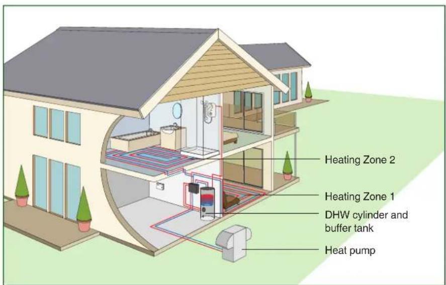
text_image
Heating Zone 2 Heating Zone 1 DHW cylinder and buffer tank Heat pump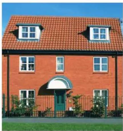
natural_image
Exterior view of a two-story brick house with red tiled roof and green entrance, surrounded by fence and lawn (no signage or text visible)System integration with existing systems
The WPM controller also allows Dimplex heat pumps to be efficiently integrated in 'bi-valent' mode with existing systems. When combined in parallel with an existing boiler, the heat pump manager regulates the boiler in accordance to need and ensures that no excessive temperatures can enter the heating system.
This way, for example, a filled oil tank can be used up before converting to heat pump only operation later on, or provide the ability for the heat pump to manage the base heating load with supplementary support from an existing gas boiler. Such strategies provide an excellent opportunity for the installation of heat pumps in existing homes and buildings.
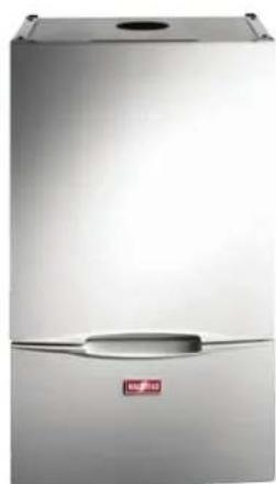
natural_image
Exterior view of a modern stainless steel refrigerator with a small handle and red logo (no visible text or symbols)Integration with other renewables
For optimal integration of renewable heat sources, the heat pump manager offers an operating mode developed especially for purpose. Thermal solar energy systems or biomass boilers feed into a renewable cylinder fitted with an additional heat exchanger which, at a sufficient temperature level, gives priority to this energy for heating or hot water, over riding the operation of the heat pump.
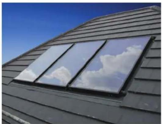
natural_image
Exterior view of a modern building with solar panels under a clear blue sky (no text or symbols visible)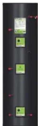
natural_image
Vertical panel with three green square buttons and red connectors at top, no visible text or symbolsSmartRad®
The perfect heat pump partner
Dimplex SmartRad is an intelligent fan convector designed specifically to work with heat pumps.
Controllable, responsive and attractively designed SmartRad offers a practical, energy efficient alternative to underfloor heating as a low temperature heating system.
Containing only 5% of the water volume of a conventional radiator, SmartRad's low thermal mass means heat up time, responsiveness and ultimately comfort are significantly improved.

natural_image
Modern living room interior with large window overlooking cityscape, featuring a TV and chessboard (no text or symbols visible)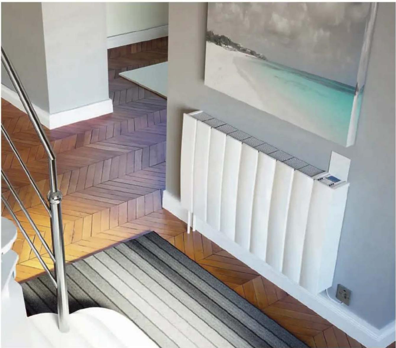
natural_image
Interior staircase with wooden flooring and a water tank, no visible text or symbols| Operating limits | SRX080 | SRX120 | SRX140 | SRX180 |
| Heating water system/return °C | Max. 85/Min. 15 at 150 L/h | |||
| Performance | *at medium fan speed and air inlet temp of 20°C | |||
| Heating capacity* mean water flow temp 40°C (kW) | 0.6 | 0.9 | 1.1 | 1.5 |
| Heating capacity* mean water flow temp 45°C (kW) | 0.8 | 1.1 | 1.4 | 1.8 |
| Heating capacity* mean water flow temp 50°C (kW) | 1.0 | 1.4 | 1.7 | 2.2 |
| Heating capacity* mean water flow temp 55°C (kW) | 1.1 | 1.6 | 2.0 | 2.6 |
| Heating capacity* mean water flow temp 60°C (kW) | 1.3 | 1.8 | 2.3 | 2.9 |
| Sound pressure level at 1m dB (A) | ||||
| Low | 26 | |||
| Medium | 29 | |||
| Boost | 36 | |||
| Air flow rate | ||||
| Low (m2/hr) | 60 | 100 | 120 | 160 |
| Medium (m2/hr) | 125 | 190 | 225 | 300 |
| Boost (m2/hr) | 228 | 345 | 410 | 540 |
| Dimensions (mm) HxWxD | 530x503 x145 | 530x670 x145 | 530x740 x145 | 530x911 x145 |
| Weight (kg) | 13 | 16 | 18 | 23 |
| Power input (W) | ||||
| Low | 17 | 22 | 26 | 24 |
| Medium | 20 | 32 | 40 | 35 |
| Boost | 27 | 47 | 60 | 53 |
| Standby power | 1W | |||
| Nominal voltage/fuse rating (V/A) | ~230/3 | |||
| Hydraulic connections | 15mm left and/or right hand connection or from rear | |||
| Water content (l) | 0.31 | 0.43 | 0.48 | 0.60 |
| Cable supplied | 1 metre | |||
Key features
- Ideal for use with heat pumps
- Cost effective, practical alternative to underfloor heating
- Designed for low water temperature operation:
• Optimises heat pump CoP
• Reduces heat pump running costs
• More energy efficient than conventional radiators:
• 40% less energy consumption to bring a room from 10°C to 21°C
- Fast response/room heat up due to very low water content:
• 2x faster than conventional radiators
• Integral electronic
thermostatic control
• Optional plug-in 24-hour or 7-day programmers
• Stylish compact design, with a choice of metal or glass fronts
Model range
| Finish | Nominal output kW | |
| 0.8 | 1.2 | |
| White metal | SRX080M | SRX120M |
| White glass SRX080WG SRX120WG | ||
| Black glass | SRX080BG | SRX120BG |
| Finish | Nominal output kW | |
| 1.4 | 1.8 | |
| White metal | SRX140M | SRX180M |
| White glass SRX140WG SRX180WG | ||
| Black glass | SRX140BG | SRX180BG |
Installers
Accredited Installers
Heat pumps are one of the most efficient and economical heating systems available provided the individual components of the system – the heat source, the heat pump itself and the connected heating system, are properly matched.
In order to ensure the highest levels of quality and to provide peace of mind, Dimplex has an established network of Accredited Heat Pump Installer Partners, all accredited under the Microgeneration Certification Scheme and fully trained and experienced in the installation, commissioning and after sales support of Dimplex heat pump products.
Installer Training
Dimplex believe that the key to success in the heat pump market is through thorough and robust installer training to ensure installations are provided to a high standard and maximise the energy efficiency of our customers' investment.
In addition to an Accredited Installer network we also provide dedicated training courses for new installers, covering installation of our range of ground and air source heat pumps. As the public interest in the environment and renewable energy products in particular increases, training ensures our installers are better equipped to satisfy our customers' requirements.
Microgeneration Certification Scheme
The Microgeneration Certifi cation Scheme (MCS) is intended to provide a robust third party certifi cation scheme for microgeneration products and installers and is designed to underpin the government's renewable energy incentive schemes. Grants and incentives will only be available to applicants using both products and installers certifi ed under the Microgeneration Certifi cation Scheme.
The scheme evaluates products and installers against robust criteria for each of the microgeneration technologies, providing greater protection for consumers and ensuring that the government's grant money is spent in an effective manner.
Dimplex recognises the importance of such schemes in helping to build a UK heat pump industry based on quality and good practice, which will make a substantial contribution to cutting the UK's dependency on fossil fuels and its carbon dioxide emissions.
Dimplex actively supports the scheme and we encourage all Dimplex heat pump installers to also become certified, giving our customers assurance as to the quality of our products and their installation and providing a means of accessing government grants.
For more information visit: www.mircrogenationcertification.org

text_image
success ough aining ded to a energy vestment. faller rated rs, e of nps. ronment s consumers and ensuring that the government's grant money is spent in an effective manner.Support information
As well as the most extensive range of heat pumps in the UK, Dimplex also has a wealth of support information available.

text_image
BCDimplex Project scale BCDimplex Project profile BCDimplex Project outline BCDimplex Project profile BCDimplex Project outline BCDimplex Project profile BCDimplex Project profile BCDimplex Project profile BCDimplex Project profile BCDimplex Project profile BCDimplex Project profile BCDimplex Project profile BCDimplex Project profile BCDimplex Project profile BCDimplex Project profile BCDimplex Project profile BCDimplex Project profile BCDimplex Project profile BCD Simplex Project profile BCD Simplex Project profile BCD Simplex Project profile BCD Simplex Project profile BCD Simplex Project profile BCD Simplex Project profile BCD Simplex Project profile BCD Simplex Project profile BCD Simplex Project profile BCD Simplex Project profile BCD Simplex Project profile BCD Simplex Project profile BCD Simplex Project ProfileCase Studies
Dimplex heat pumps have been installed in a wide variety of installations across domestic and commercial applications from private and social housing developments, through to schools, hospitals, nursing homes and retail parks.
To view a selection of case studies, simply visit www.dimplexrenewables.co.uk

text_image
PROJECT PLANNING AND INSTALLATION MANUAL MOST PLUMBING FOR HEATING AND HOT WATER PREPARATION © BC Dimplex BC Dimplex PROFESSIONAL WRITTEN & COLDING © 2015-03-06 © 2015-03-07 © 2015-03-08 © 2015-03-09 © 2015-03-10 © 2015-03-11 © 2015-03-12 © 2015-03-13 © 2015-03-14 © 2015-03-15 © 2015-03-16 © 2015-03-17 © 2015-03-18 © 2015-03-19 © 2015-03-20 © 2015-03-21 © 2015-03-22 © 2015-03-23 © 2015-03-24 © 2015-03-25 © 2015-03-26 © 2015-03-27 © 2015-03-28 © 2015-03-29 © 2015-03-30 © 2015-03-31 © 2015-03-32 © 2015-03-33 © 2015-03-34 © 2015-03-35 © 2015-03-36 © 2015-03-37 © 2015-03-38 © 2015-03-39 © 2015-03-40 © 2015-03-41 © 2015-03-42 © 2015-03-43 © 2015-03-44 © 2015-03-45 © 2015-03-46 © 2015-03-47 © 2015-03-48 © 2015-03-49 © 2015-03-50 © 2015-03-51 © 2015-03-52 © 2015-03-53 © 2015-03-54 © 2015-03-55 © 2015-03-56 © 2015-03-57 © 2015-03-58 © 2015-03-59 © 2015-03-60 © 2015-03-61 © 2015-03-62 © 2015-03-63 © 2015-03-64 © 2015-03-65 © 2015-03-66 © 2015-03-67 © 2015-03-68 © 2015-03-69 © 2015-03-70 © 2015-03-71 © 2015-03-72 © 2015-03-73 © 2015-03-74 © 2015-03-75 © 2015-03-76 © 2015-03-77 © 2015-03-78 © 2015-03-79 © 2015-03-80 © 2015-03-81 © 2015-03-82 © 2015-03-83 © 2015-03-84 © 2015-03-85 © 2015-03-86 © 2015-03-87 © 2015-03-88 © 2015-03-89 © 2015-03-90 © 2015-03-91 © 2015-03-92 © 2015-03-93 © 2015-03-94 © 2015-03-95 © 2015-03-96 © 2015-03-97 © 2015-03-98 © 2015-03-99 © 2015-04 -Planning Guide
This comprehensive technical guide provides all the detailed information a specifier or installer needs including performance data, system design and other relevant support information documentation.
Available as a download on our website, or as a printed document – ordered via our website or by phoning 0845 601 5111.
text_image
ECDimplex renewables® ecotalk A world of expertise Dimplex heat pumps earn top marks at college A new college campus listing and developing the climate-based differences, greenest and heat measures in renewable energy efficiency and sustainable energy efficiency. The 120MW technology is in 18-24 years. We are the leading field for the Ecochex project. Our projects are and we will be used to achieve the Ecochex project. The highest investment Figure 3: The ECOchex project is now and we will be used to achieve the Ecochex project. Our projects are and we will be used to achieve the Ecochex project. The ECOchex project is now and we will be used to achieve the Ecochex project. The ECOchex project is now and we will be used to achieve the Ecochex project.Newsletters
In addition to product based literature, we also produce a regular newsletter – EcoTalk which covers all the latest news and views of the industry.
Read an interactive copy at www.dimplexrenewables.co.uk

text_image
BCDimplex Name File Region Environment Guide Growth of Market - Heating Home View On Renewable Energy Solutions for domestic and commercial applications Introducing smartfad investigent for connection Intelligent heating for a low energy world Find out more (here) • 4V battery heat pump providing heating, but water and cooling using hot from the protection • Solar panel heat pump providing heating, but water and cooling heating energy from the ground • Solar panel heat pump providing heating, but water and cooling • Solar panel heat pump providing the maximum energy from the minimum solar power supply to protection and coolingElectronic support
In addition to web based product information, we also have links to more detailed information on Dimplex heat pumps to assist those involved in the specification or installation.
• Individual Product Data Sheets
- On-line Cost Calculator. This powerful tool helps to select the correct heat pump for your application and compare the running costs with other types of heating systems.
- On-line Hydraulic Integration Diagrams. Aids system design and installation by creating customised hydraulic schematic diagrams of the heat pump system for your project.
Please visit www.dimplexrenewables.co.uk for full details.
Technical specifications
Typical system configuration and accessories

flowchart
graph LR
    A["Heating Circuit"] --> B["Buffer Tank"]
    B --> C["DHW Cylinder"]
    C --> D["Flow meter"]
    D --> E["LA MI Heat Pump"]
    F["Power Source"] --> D
    style A fill:#f9f,stroke:#333
    style E fill:#ccf,stroke:#333
Domestic Air Source Heat Pumps: LA MI range
The diagram below shows a typical LA MI heat pump configuration for heating and domestic hot water including typical accessories required for a single heating circuit.
(Note this is for illustrative purposes only and is not intended as a full hydraulic schematic)
| Heat pump | Qty | |
| LA 6/9/12/16 MI | Inverter air source heat pump | 1 |
| Heating and hot water accessories | ||
| MFK114 | Isolation valves | 1 |
| TNDN25/32 | Flow rate checker | 1 |
| HRST28 | Two port valves and room stat | 1 |
| NTC2 | DHW temp sensor | 1 |
| ECSxxxHP75-580 | Heat pump cylinder with buffer | 1 |
| SmartRad | ||
| SRX08 | SmartRad fan convectors based dependant upon room size. Available in Metal, White glass and Black glass. | |
| SRX120 | ||
| SRX140 | ||
| SRX180 | ||
| LA 6 MI | LA 9 MI | LA 12 MI | LA 16 MI | |
| Operating Limits | ||||
| Heating water system/return °C | Max. 55/Min. 25 | Max. 55/Min. 25 | Max. 55/Min. 25 | Max. 55/Min. 25 |
| Air °C | -20 to +35 | -20 to +35 | -20 to +35 | -20 to +35 |
| Performance | ||||
| Heating capacity A7/W35 (kW) | 6 | 9 | 12 | 16 |
| CoP A7/W35 | 4.4 | 3.85 | 4.67 | 4.23 |
| Heating capacity A2/W35 (kW) | 6 | 9 | 12 | 16 |
| CoP A2/W35 | 3.7 | 3.4 | 3.87 | 3.48 |
| A-weighted sound power level dB(A) | 58 | 61.5 | 62 | 64 |
| Sound pressure level at 1m with Q=2 to MIS 3005 | 54 | 54 | 54 | 56 |
| Heating water flow rate m3/h | 1 | 1.6 | 2.1 | 2.8 |
| Air flow m3/h | 2800 | 3100 | 4800 | 5400 |
| Dimensions HxWxD (mm) | 865 x 1283 x 320 | 865 x 1283 x 320 | 1410 x 1284 x 400 | 1410 x 1284 x 400 |
| Weight (kg) | 122 | 122 | 165 | 165 |
| Nominal voltage/fuse rating (V/A) | 230/20 | 230/20 | 230/20 | 230/20 |
| Starting current (inverter driven) (A) | Gradual increase from 0 – 6 | Gradual increase from 0 – 10 | Gradual increase from 0 – 12 | Gradual increase from 0 – 13 |
| Defrosting | Automatic, reverse cycle | |||
Domestic Air Source Heat Pumps: LA MS/LA PMS ranges
The diagram to the right shows a typical LA MS/LA PMS heat pump configuration for heating and domestic hot water including typical accessories required for a single heating circuit.
(Note this is for illustrative purposes only and is not intended as a full hydraulic schematic)

flowchart
graph LR
    A["DHW Cylinder"] --> B["Heating Circuit"]
    B --> C["Buffer Tank"]
    C --> D["JP25-60"]
    D --> E["WPM Control Unit"]
    E --> F["Heat Pump"]
    F --> G["JP25-60"]
    G --> H["JP25-60"]
    H --> I["Heating Circuit"]
    I --> J["JP25-60"]
    J --> K["Heating Circuit"]
    K --> L["JP25-60"]
    L --> M["Heating Circuit"]
    M --> N["JP25-60"]
    N --> O["Heating Circuit"]
    O --> P["JP25-60"]
    P --> Q["Heating Circuit"]
    Q --> R["JP25-60"]
    R --> S["Heating Circuit"]
    S --> T["JP25-60"]
    T --> U["Heating Circuit"]
    U --> V["JP25-60"]
    V --> W["Heating Circuit"]
    W --> X["JP25-60"]
    X --> Y["Heating Circuit"]
    Y --> Z["JP25-60"]
    Z --> AA["Heating Circuit"]
    AA --> AB["JP25-60"]
    AB --> AC["Heating Circuit"]
    AC --> AD["JP25-60"]
    AD --> AE["Heating Circuit"]
    AE --> AF["JP25-60"]
    AF --> AG["Heating Circuit"]
    AG --> AH["JP25-60"]
    AH --> AI["Heating Circuit"]
    AI --> AJ["JP25-60"]
    AJ --> AK["Heating Circuit"]
    AK --> AL["JP25-60"]
    AL --> AM["Heating Circuit"]
    AM --> AN["JP25-60"]
    AN --> AO["Heating Circuit"]
    AO --> AP["JP25-60"]
    AP --> AQ["Heating Circuit"]
    AQ --> AR["JP25-60"]
    AR --> AS["Heating Circuit"]
    AS --> AT["JP25-60"]
    AT --> AU["Heating Circuit"]
    AU --> AV["JP25-60"]
    AV --> AW["Heating Circuit"]
    AW --> AX["JP25-60"]
    AX --> AY["Heating Circuit"]
| Heat pump | Qty | |
| LA 9/11/16 MS | Air source heat pump (heating) | 1 |
| LA 8/14 PMS | Air source heat pump (heating/cooling) | 1 |
| Heating and hot water accessories | ||
| ECSxxxHP-580* | Heat pump cylinder | 1 |
| PSW100/PSW200 | 100L/200L Buffer tank | 1 |
| UP25-60/UP25-80 | Heating/DHW circulation pumps | 1 |
| CTHK630/631 | Buffer immersions | 1 |
| Controller accessories | ||
| EVL 999/6/7/8-1 | Controller connecting cable (heating) | 1 |
*Dependent on required heat pump flow rate + wall thermostat
| LA 9 MS | LA 11 MS | LA 16 MS | LA 8 PMS | LA 14 PMS | ||
| Operating Limits | ||||||
| Heating water system/return °C | Up to 55 +/-2 | Up to 55 +/-2 | Up to 55 +/-2 | Up to 65 +/-2 | Up to 65 +/-2 | |
| Air °C | -20 to +35 | -25 to +35 | -25 to +35 | -25 to +35 | -20 to +35 | |
| Performance | 1xcompressor | 2xcompressors | ||||
| Heating capacity A7/W35 (kW) | 9.5 | 10.9 | 15.1 | 8.0 | 7.4 | 13.3 |
| CoP A7/W35 | 3.9 | 3.9 | 3.6 | 3.8 | 3.7 | 3.9 |
| Heating capacity A2/W35 (kW) | 7.9 | 9.0 | 12.5 | 6.0 | 5.8 | 10.2 |
| CoP A2/W35 | 3.4 | 3.3 | 3.0 | 3.1 | 2.9 | 3.1 |
| Heating water flow with internal pressure differential at A7/W35 | 1.7 m3/hr@7600Pa | 1.9 m3/hr@10900Pa | 2.6 m3/hr@14600Pa | 1.5 m3/hr@7800Pa | 2.4 m3/hr@10100Pa | |
| Sound pressure level at 10m (db(A)) | 33 | 33 | 34 | 32 | 35 | |
| Dimensions HxWxD (mm) | 1340 x 852 x 1050 | 1360 x 1360 x 850 | 1570 x 1550 x 850 | 1361 x 1362 x 852 | 1571 x 1552 x 852 | |
| Weight (kg) | 189 | 219 | 264 | 232 | 256 | |
| Refrigerant: type/total charge weight (kg) | R404A/3.8 | R404A/2.5 | R404A/3.1 | R290/1.0 | R290/1.8 | |
| Nominal voltage | 230/1ph | 230/1ph | 230/1ph | 230/1ph | 230/1ph | |
| Starting current with soft start (A) | 29 | 38 | 45 | 30 | 28 | |
| Defrosting | Automatic, reverse cycle | Automatic, hot gas | ||||
Commercial Air Source Heat Pumps: LA TU range
The diagram to the right shows a typical LA TU heat pump configuration for heating and domestic hot water including typical accessories required for a single heating circuit.
(Note this is for illustrative purposes only and is not intended as a full hydraulic schematic)

flowchart
graph TD
    A["DHW Cylinder"] --> B["Heating Circuit"]
    B --> C["Buffer Tank"]
    C --> D["DDV25 DDV32"]
    D --> E["WWM 25"]
    E --> F["WPM ECON+ Control Unit"]
    F --> G["LL with Brick Box"]
    G --> H["LA 17-60TU Heat Pump"]
    I["WWM 25"] --> D
    J["WWM 25"] --> E
| Heat pump | Qty | |
| LA 17/25/40/60 TU | Air source heat pump (heating) | 1 |
| Heating and hot water accessories | ||
| ECS300HP-580/WWSP332UK/880UK/900UK | Domestic hot water cylinder | 1 |
| PSW100/200/500/1000 | Buffer tank | 1 |
| UP25-60/UP25-80 | Heating/DHW circulation pumps | 1 |
| UP32-70 | Heating/DHW circulation pumps | 1 |
| CTHK632/3/4/5 | Buffer immersions | 1 |
| DDV25/32* | Dual differential pressure less module | 1 |
| WWM25* | Heating Circuit/hot water module | 1 |
| WPG 25/32 | Rear cylinder circulation pump mounting kit | 1 |
| Controller accessories | ||
| WPM EconPlus | Heat pump controller (included with heatpump) | 1 |
| EVL 10/20/30/60U | Controller connecting cable (heating) | 1 |
*Dependent on required heat pump flow rate
| LA 17 TU | LA 25 TU | LA 40 TU | LA 60 TU | |
| Operating Limits | ||||
| Heating output A7/W35 (kW) | ||||
| 1 compressor | 10.0 | 13.9 | 20.0 | 31.9 |
| 2 compressors | 19.6 | 26.1 | 35.7 | 60.1 |
| CoP A7/W35 | ||||
| 1 compressor | 4.5 | 4.5 | 4.6 | 4.3 |
| 2 compressors | 4.4 | 4.4 | 4.4 | 4.1 |
| Heat Output A2/W35 (kW) | ||||
| 1 compressor | 8.2 | 11.3 | 16.8 | 26.4 |
| 2 compressors | 14.6 | 19.6 | 30.0 | 50.6 |
| CoP A2/W35 | ||||
| 1 compressor | 3.8 | 3.8 | 3.9 | 3.7 |
| 2 compressors | 3.7 | 3.7 | 3.8 | 3.6 |
| Mechanical/Electrical | ||||
| Connection voltage | 400 | 400 | 400 | 400 |
| Maximum flow temperature (°C) | 58 | 58 | 58 | 65 |
| Thermal energy metering | Integrated as standard | |||
| Minimum water heating flow @internal pressure differential | 1.7m^3/hr @1100Pa | 2.2m^3/hr @ 2100Pa | 3.0m^3/hr @ 950Pa | 5.3m^3/hr @ 2100Pa |
| Air flow ( m^3/hr ) | 5500 | 7500 | 11000 | 14000 |
| Sound pressure level at 10m dB(A) | 37 | 40 | 43 | 50 |
| Refrigerant: type/Total charge weight (kg) | R404A/8.2 | R404A/10.2 | R404A/11.8 | R417A/19.4 |
| Height (mm) | 1940 | 1940 | 2100 | 2300 |
| Width (mm) | 1600 | 1600 | 1735 | 1900 |
| Depth (mm) | 955 | 955 | 980 | 1000 |
| Weight (including packaging) (kg) | 436 | 510 | 585 | 915 |
| Nominal voltage/fuse rating (V/A) | 400/16 | 400/25 | 400/25 | 400/29.5 |
| Starting current with soft start | 17 | 22 | 30 | 78 |
| Defrosting | Automatic, reverse cycle | |||
Commercial Air Source Heat Pumps: LA AS/LA PS ranges
The diagram to the right shows typical LA AS/LA PS heat pump configuration for heating and domestic hot water including typical accessories required for a single heating circuit.
(Note this is for illustrative purposes only and is not intended as a full hydraulic schematic)
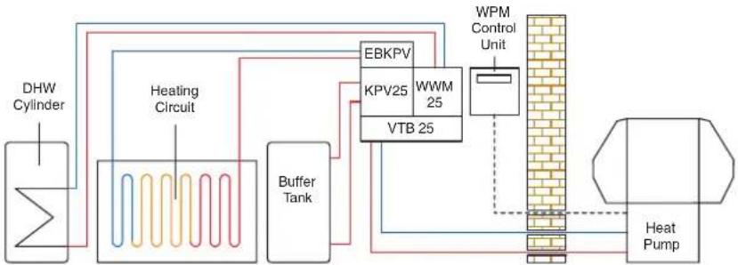
flowchart
graph TD
    A["DHW Cylinder"] --> B["Heating Circuit"]
    B --> C["Buffer Tank"]
    C --> D["EBKPV"]
    D --> E["KPV25"]
    D --> F["WWM 25"]
    D --> G["VTB 25"]
    G --> H["WPM Control Unit"]
    H --> I["Heat Pump"]
    I --> J["Output"]
| Heat pump Qty | ||
| LA 20/24/28/40 AS | Air source heat pump (heating) | 1 |
| LA 17/22/26 PS | Air source heat pump (heating/cooling) | 1 |
| Heating and hot water accessories | ||
| ECS300HP-580/WWSP332UK/WWSP880UK | 300L domestic hot water cylinder | 1 |
| PSW500/1000 | 500L Buffer tank | 1 |
| UP60/UP80 | Heating/DHW circulation pumps | 1 |
| UP32-70 | Heating/DHW circulation pumps | 1 |
| CTHK631/2/3/4/5/6 | Buffer immersions | 1 |
| FLH60 | Three phase 6.0kW flange heater | 1 |
| FLHU70 | Three phase 2.0/2.7/4.0kW variable output flange heater | 1 |
| DDV32* | Dual differential pressure less module | 1 |
| KPV25* | Compact manifold | 1 |
| EBKPV* | Extension module for KPV | 1 |
| WWM25* | Heating circuit/hot water module | 1 |
| VTB25* | Manifold bar | 1 |
| Controller accessories | ||
| WPM 2006 Plus | Heat pump controller (included with heatpump) | |
| EVL 995/6/7/8-1 | Controller connecting cable (heating) | 1 |
*Dependent on required heat pump flow rate
| LA 20 AS | LA 24 AS | LA 28 AS | LA 40 AS | |
| Operating Limits | ||||
| Heating water supply/return °C | Max. 55/Min. 18 | Max. 55/Min. 18 | Max. 55/Min. 18 | Max. 55/Min. 18 |
| Air °C | -20 to +35 | -20 to +35 | -20 to +35 | -20 to +35 |
| Cooling flow °C | - | - | - | - |
| Air °C | - | - | - | - |
| Performance | ||||
| Heating capacity A7/W35 (kW) | ||||
| 1 compressor | 9.8 | 13.1 | 14.2 | 20.2 |
| 2 compressors | 16.6 | 24.8 | 25.8 | 36.3 |
| Coefficient of Performance A7/W35 (kW)* | ||||
| 1 compressor | 3.2 | 3.4 | 3.1 | 4.7 |
| 2 compressors | 3.1 | 3.6 | 3.4 | 4.5 |
| Cooling capacity A27/W18 (kW)* | - | - | - | - |
| Coefficient of Performance A27/W18* | - | - | - | - |
| Minimum heating flow @ internal pressure differential (m3/h/Pa) | 1.8/3700 | 2.3/5900 | 2.3/3100 | 4.0/4700 |
| Sound pressures level at 10m dB (A) | 37 | 41 | 41 | 43 |
| Refrigerant: type/total charge weight (kg) | R404A/3.7 | R404A/4.2 | R404A/4.2 | R404A/11.8 |
| Dimensions HxWxL (mm) | 1570 x 1550 x 850 | 1710 x 1680 x 1000 | 1710 x 1680 x 1000 | 2100 x 1735 x 890 |
| Weight (including packaging) (kg) | 284 | 351 | 355 | 585 |
| Nominal voltage/fuse rating (V/A) 400/20 400/25 400/25 | 400/25 | |||
| Starting current with soft start (A) | 23 | 24 | 25 | 30 |
*Performance standards measured to EN255
Commercial Air Source Heat Pumps:
LA PS range, hot water only
The diagram to the right shows typical LA PS heat pump configuration for domestic
hot water.
(Note this is for illustrative purposes only and is not intended as a full hydraulic schematic)
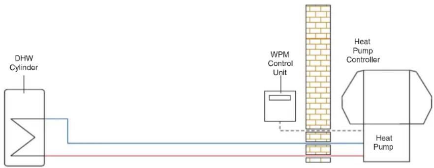
flowchart
graph LR
    A["DHW Cylinder"] --> B["WPM Control Unit"]
    B --> C["Heat Pump Controller"]
    C --> D["Heat Pump"]
| Heat pump Qty | ||
| LA 17/22/26/PS | Air source heat pump | 1 |
| Heating and hot water accessories | ||
| ECS300HP-580/WWSP332UK/880UK/900UK | 300L/400L/500L domestic hot water cylinder | 1 |
| Controller accessories | ||
| WPM 2006 Plus | Heat pump controller (included with heatpump) | |
| EVL 995/6/7/8-1 | Controller connecting cable (heating) | 1 |
*Dependent on required heat pump flow rate
| LA 17 PS | LA 22 PS | LA 26 PS | |
| Operating Limits | |||
| Heating water supply/return °C | Max. 65/Min. 18 | Max. 65/Min. 18 | Max. 65/Min. 18 |
| Air °C | -20 to +35 | -20 to +35 | -20 to +35 |
| Performance | |||
| Heating capacity A7/W35 (kW) | |||
| 1 compressor | 9.6 | 12.0 | 13.3 |
| 2 compressors | 16.6 | 21.1 | 22.9 |
| Coefficient of Performance A7/W35 (kW)* | |||
| 1 compressor | 3.4 | 3.6 | 3.5 |
| 2 compressors | 3.4 | 3.5 | 3.5 |
| Minimum heating flow @ internal pressure differential (m3/h/Pa) | 1.6 / 2900 | 2.0 / 4500 | 2.2 / 3100 |
| Sound pressures level at 10m dB (A) | 37 | 41 | 41 |
| Refrigerant: type/total charge weight (kg) | R290 / 1.8 | R290 / 2.2 | R290 / 2.5 |
| Dimensions HxWxL (mm) | 1570 x 1550 x 850 | 1710 x 1680 x 1000 | 1710 x 1680 x 1000 |
| Weight (including packaging) (kg) | 330 | 360 | 371 |
| Nominal voltage / fuse rating (V/A) | 400 / 20 | 400 / 20 | 400 / 25 |
| Starting current with soft start (A) | 23 | 25 | 30 |
*Performance standards measured to EN14511
Domestic Ground Source Heat Pumps: SI ME range
Domestic High Temperature Ground Source
Heat Pumps: SIH ME range
The diagram below shows a typical SI ME/SIH ME heat pump configuration for heating and domestic hot water including typical accessories required for a single heating circuit.
(Note this is for illustrative purposes only and is not intended as a full hydraulic schematic)

flowchart
graph LR
    A["DHW Cylinder"] --> B["Heating Circuit"]
    B --> C["UP 25-60"]
    C --> D["UP 25-60"]
    D --> E["UP 25-60"]
    E --> F["Buffer Tank"]
    F --> G["Heat Pump"]
    G --> H["Brick Wall"]
| Heat pump | Qty | |
| SI 14 ME | Ground source heat pump (heating) | 1 |
| 4/6/9/11 ME | Ground source heat pump (high temp) | 1 |
| Heating and hot water accessories | ||
| ECSxxxHP-580* | Domestic hot water cylinder | 1 |
| PSW100/200 | 100L/200L Buffer tank | 1 |
| PSP100E | 100L under Buffer cylinder | 1 |
| UP60/UP80 | Heating/DHW circulation pumps | 1 |
| Ground/Controller accessories | ||
| SZB 680/690 | Ground loop circuit package | 1 |
| APSVT | Ground loop circuit manifold connection kit | 1 |
| SVT200/300/400 | Ground circuit manifold (2/3/4 circuits) | 1 |
| WPM 2007 | Heat pump controller (built into product) | |
*Dependent on required heat pump flow rate
| SI 14 ME | SIH 4 ME | SIH 6 ME | SIH 9 ME | SIH 11 ME | |
| Operating Limits | |||||
| Heating water supply/return °C | Max. 58/Min. 18 | Max. 70/Min. 18 | Max. 70/Min. 18 | Max. 70/Min. 18 | Max. 70/Min. 18 |
| Brine °C | -5 to +25 | -5 to +25 | -5 to +25 | -5 to +25 | -5 to +25 |
| Anti-freeze agent | Monoethylene glycol | ||||
| Minimum anti-freeze concentration | 25% | 25% | 25% | 25% | 25% |
| Performance | |||||
| Heating capacity B0/W35 (kW)* | 14.8 | 4.3 | 6 | 8.9 | 10.7 |
| Coefficient of Performance B0/W35 | 3.9 | 3.8 | 4.1 | 4.0 | 4.5 |
| Heating flow with internal pressure differential (m3/h/Pa) | 1.3 / 4800 | 0.75 / 1000 | 1.0 / 4100 | 1.55 / 6400 | 1.9 / 7000 |
| Sound power level at 10m (db(A)) | 56 | 55 | 56 | 56 | 57 |
| Refrigerant: type/total charge weight (kg) | R407C/2.2 | R134A/1.5 | R134A/1.8 | R134A/2.2 | R134A/2.4 |
| Dimensions HxWxD (mm) | 805 x 650 x 462 | 805 x 650 x 462 | 805 x 650 x 462 | 805 x 650 x 462 | 805 x 650 x 462 |
| Weight (including packaging) (kg) | 130 | 118 | 118 | 130 | 133 |
| Nominal voltage / fuse rating (V/A) | 230 / 32 | 230 / 20 | 230 / 20 | 230 / 25 | 230 / 32 |
| Starting current with soft start (A) | 50 | 26 | 38 | 43 | 45 |
*Performance standards measured to EN14511
Domestic Ground Source Heat Pumps: SIK ME range
The diagram below shows a typical SIK ME heat pump configuration for heating and domestic hot water including typical accessories required for a single heating circuit.
(Note this is for illustrative purposes only and is not intended as a full hydraulic schematic)
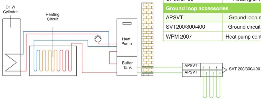
flowchart
graph LR
    A["DHW Cylinder"] --> B["Heating Circuit"]
    B --> C["Heat Pump"]
    C --> D["Buffer Tank"]
    D --> E["Ground loop accessories"]
    E --> F["APSVT"]
    E --> G["APSVT"]
    F --> H["Ground loop n"]
    G --> I["Ground circuit"]
    H --> J["WPM 2007"]
    I --> K["Heat pump cont"]
| Heat pump Qty | ||
| SIK 16 ME | Ground source heat pump | 1 |
| Heating and hot water accessories | ||
| PSP100E | 100L under-unit buffer tank | 1 |
| VSH KS | Buffer tank connection hose | 1 |
| WWSP 442 EUK | 400L hot water storage tank | 1 |
| VSW KS | Hot water tank connection hose | 1 |
| UP60/UP80 | Heating/DHW circulation pumps | 1 |
| Ground loop accessories | ||
| APSVT | Ground loop manifold connection kit | 1pr |
| SVT200/300/400 | Ground circuit manifold 2/3/4 circuits 1pr | |
| WPM 2007 | Heat pump controller (built into product) | |
Commercial Source Heat Pumps: SI TE range (24 – 37kW)/SI TU range Reversible Ground Source Heat Pumps: SI TER+ range
The diagram below shows a typical SI TE heat pump configuration for heating and domestic hot water including typical accessories required for a single heating circuit.
(Note this is for illustrative purposes only and is not intended as a full hydraulic schematic)
| Heat pump | Qty | |
| SI 24/30/37 TE | Ground source heat pump | 1 |
| SI 18/22 TU | Ground source heat pump | 1 |
| Heating and hot water accessories | ||
| PSW200/500 | 200L/500L buffer tank | 1 |
| WWSP880UK/900UK | 400L/500L domestic hot water cylinder | 1 |
| UP60/UP80 | Heating/DHW circulation pumps | 1 |
| UP32-70 | Heating/DHW circulation pumps | 1 |
| FLH60 | Three phase 6.0kW flange heater | 1 |
| FLHU70 | Three phase 2.0/2.7/4.0kW variable output flange heater | 1 |
| DDV32* | Dual differ. pressure less module | 1 |
| WWM25* | Heating circuit/hot water module | 1 |
| Ground/Controller accessories | ||
| SZB700/710/250/400 | Ground loop circuit package | 1 |
| APSVT† | Ground circuit manifold connection kit 1 | |
| SVT200/300/400† | Ground circuit manifold 2/3/4 circuits | 1 |
| WPM | Heat pump controller (built into product) | |
*Dependent on required heat pump flow rate
^ Not suitable for SI 24/30/37 TE
WPM2007 included in pack for TE / WPM EconPlus for TU

flowchart
graph LR
    A["DHW Cylinder"] --> B["Heating Circuit"]
    B --> C["Buffer Tank"]
    C --> D["DDV"]
    D --> E["WWM 25"]
    E --> F["SI TE Heat Pump"]
    F --> G["528/700/710/240/300"]
    G --> H["APSVT"]
    H --> I["SVT 200/300/400"]
    style A fill:#f9f,stroke:#333
    style I fill:#bbf,stroke:#333
| SIK 16 ME | |
| Operating Limits | |
| Heating water supply/return °C | Max. 55/Min. 18 |
| Brine (heating) °C | -5 to +25 |
| Anti-freeze agent | Monoethylene glycol |
| Maximum anti-freeze concentration | 25% |
| Performance | |
| Heating capacity B0/W35 | 15.8 |
| Coefficient of Performance B0/W35 | 4.2 |
| Heating flow @ internal pressure differential (m3/h/Pa) | 1.3 / 3500 |
| Sound power level dB(A) | 51 |
| Refrigerant: type/total charge weight (kg) | R407C/2.3 |
| Dimensions H x W x L (mm) | 1115 x 652 x 688 |
| Weight (including packaging) (kg) | 203 |
| Nominal voltage / fuse rating (V/A) | 230/32 |
| Starting current with soft starter (A) | 50 |
| SI 18 TU | SI 22 TU | SI 24 TE | SI 30 TE | SI 30 TER+ | SI 37 TE | |
| Operating Limits | ||||||
| Heating water supply/return °C | Max. 62/Min.20 | Max. 58/Min. 18 | Max. 60/Min. 18 | |||
| Brine (heating) °C | -5 to +25 | |||||
| Anti-freeze agent | Monoethylene glycol | |||||
| Minimum anti-freeze concentration | 25% | |||||
| Operating Limits | ||||||
| Cooling water supply | - | 5°C to 30°C | - | |||
| Brine (cooling) °C | - | -5°C to +25°C | - | |||
| Performance (Heating) | ||||||
| Heating capacity B/0/W35 (kW)* | ||||||
| 1 compressor | 17.5 | 22.9 | 12.7 | 14.4 | 15.2 | 18.3 |
| 2 compressors | - | - | 23.7 | 31.2 | 28.6 | 35.4 |
| Coefficient of Performance B0/W35 (kW)* | ||||||
| 1 compressor | 4.7 | 4.4 | 4.3 | 4.2 | 4.2 | 4.5 |
| 2 compressors | - | - | 4.1 | 4.6 | 3.8 | 4.3 |
| Performance (Cooling) | ||||||
| Cooling capacity B0/W18 (kW)* | ||||||
| 1 compressor | - | - | - | - | 25.4 | - |
| 2 compressors | - | - | - | - | 46.7 | - |
| Coefficient of Performance B10/W18 (kW)* | ||||||
| 1 compressor | - | - | - | - | 9.5 | - |
| 2 compressors | - | - | - | - | 7.4 | - |
| Minimum heating flow @ internal pressure differential (m3/h/Pa) | 1.5 / 4500 | 1.9 / 5000 | 2.2 / 3100 | 2.6 / 1100 | 4.7 / 2200 | 3.2 / 1650 |
| Sound power level at 10m dB (A) | 50 | 53 | 59 | 62 | 62 | 63 |
| Refrigerant: type/total charge weight (kg) | R410A/5.2 | R407C/3.7 | R404A/3.7 | R404A/7.7 | R404A/8.1 | R404A/6.8 |
| Dimensions HxWxL (mm) | 845 x 650 x 665 | 845 x 650 x 665 | 1660 x 1000 x 775 | 1440 x 775 x 1000 | 1660 x 1000 x 775 | 1660 x 1000 x 775 |
| Weight (including packaging) (kg) | 163 | 184 | 282 | 365 | 385 | 371 |
| Nominal voltage/fuse rating (V/A) | 400/16 | 400/20 | ||||
| Starting current with soft starter (A) | 28 | 25 | 20 | 25 | 26 | 26 |
*Performance standards measured to EN14511
Commercial Ground Source Heat Pumps
High Output Ground Source Heat Pumps: SI TE range (50 - 130kW)
High Temperature Ground Source Heat Pumps: SIH TE range
Reversible Ground Source Heat Pumps: SI TER+/SI TUR+ ranges
| Heat pump | Qty | |
| SI50/75/100/130TE SIH 20/40 TE SI 30/75 TER+ SI 130 TUR+ Ground Source Heat Pump | 1 | |
| Heating and hot water accessories | ||
| PSW500/1000 | Buffer tank | 1 |
| WWSP900UK | 500L domestic hot water cylinder | 1 |
| FLH60 | Three phase 6.0kW flange heater | 1 |
| FLHU70 | Three phase 2.0/2.7/4.0kW variable output flange heater | 1 |
| Ground loop controller accessories | ||
| SZB500/750/1000/1300 & SZB250/400 | ||
| WPM 2007 Heat pump controller included with heat pump | ||
The diagram below shows a typical SI TE / SI TEH heat pump configuration for heating and domestic hot water including typical accessories required for a single heating circuit.
(Note this is for illustrative purposes only and is not intended as a full hydraulic schematic)

flowchart
graph LR
    A["DHW Cylinder"] --> B["Heating Circuit"]
    B --> C["Buffer Tank"]
    C --> D["Heat Pump"]
    D --> E["SZB500-750-1000-1300-240-400"]
    E --> F["Storage Unit"]
    style A fill:#f9f,stroke:#333
    style B fill:#ccf,stroke:#333
    style C fill:#cfc,stroke:#333
    style D fill:#fcc,stroke:#333
    style E fill:#cff,stroke:#333
    style F fill:#ffc,stroke:#333
Swimming Pool Heat Pumps: LAS MT/LAS TT ranges
The diagram shows a typical LAS MT / LAS TT heat pump configuration for swimming pool heating.
(Note this is for illustrative purposes only and is not intended as a full hydraulic schematic)

flowchart
graph LR
    A["Swimming pool"] --> B["Remote control"]
    B --> C["LA MT/TT Heat Pump"]
    C --> D["Output"]
| SI 50 TE | SI 75 TE | SI 75 TER+ | SI 100 TE | SI 130 TE | SIH 20 TE | SIH 40 TE | |
| Operating Limits | |||||||
| Heating water supply/return °C | Max. 60/Min. 18 | Max. 70/Min. 18 | |||||
| Brine (heating) °C | -5 to +25 | ||||||
| Anti-freeze agent | Monoethylene glycol | ||||||
| Minimum anti-freeze concentration | 25% | ||||||
| Performance | |||||||
| Heating capacity B0/W35 (kW) | |||||||
| 1 compressor | 23.0* | 37.6* | 35.1* | 48.4* | 63.3* | 11.5† | 17.4† |
| 2 compressors | 46.7* | 75.2* | 65.3* | 96.3* | 125.8* | 21.4† | 34.2† |
| Coefficient of Performance B0/W35 (kW) | |||||||
| 1 compressor | 4.4* | 4.3* | 3.8* | 4.6* | 4.2* | 4.6† | 4.1† |
| 2 compressors | 4.5* | 4.4* | 3.5* | 4.6* | 4.3* | 4.4† | 4.1† |
| Cooling capacity B10/W18 (kW) | |||||||
| 1 compressor | - | - | 53.2 | - | - | - | - |
| 2 compressors | - | - | 98.2 | - | - | - | - |
| Coefficient of Performance B10/W18 | |||||||
| 1 compressor | - | - | 8.2 | - | - | - | - |
| 2 compressors | - | - | 6.3 | - | - | - | - |
| Minimum heating flow @ internal pressure differential (m3/h/Pa) | 4.5/2000 | 6.5/2500 | 11/6000 | 8.5/3600 | 11.5/2200 | 1.9/2310 | 3.2/1100 |
| Sound power level dB (A) | 50 | 54 | 54 | 55 | 56 | 47 | 50 |
| Refrigerant: type/total charge weight (kg) | R404A/8.6 | R404A/14.1 | R404A/16.1 | R404A/20.5 | R404A/27.0 | R134A/4.2 | R134A/8.0 |
| Dimensions HxWxL (mm) | 1890 x 1350 x 775 | 1890 x 1350 x 775 | 1890 x 1350 x 775 | 1890 x 1350 x 775 | 1890 x 1350 x 775 | 1660 x 1000 x 775 | 1890 x 1350 x 775 |
| Weight (including packaging) (kg) | 486 | 571 | 607 | 652 | 860 | 307 | 502 |
| Nominal voltage / fuse rating (V/A) | 400/50 | 400/63 | 400/63 | 400/80 | 400/80 | 400/25 | 400/63 |
| Starting current with soft starter (A) | 56 | 105 | 105 | 120 | 115 | 30 | 84 |
*Performance standards measured to EN255
^† Performance standards measured to EN255
| LAS 10 MT | LAS 15 MT | LAS 22 TT | |
| Operating Limits | |||
| Heating water supply/return °C | +10 to +40 | +10 to +40 | +10 to +40 |
| Air °C | -10 to +35 | -10 to +35 | -10 to +35 |
| Performance | |||
| Heating capacity A20/W24 (kW) | 12.1 | 16.6 | 22.3 |
| Coefficient of Performance A20/W24 | 2.9 | 3.5 | 4.4 |
| Sound pressure level at a distance of 10m dB (A) | 45 | 45 | 46 |
| Refrigerant: type/total charge weight (kg) | R407C/1.5 | R407C/1.6 | R407C/2.5 |
| Dimensions HxWxL (mm) | 860 x 127 x 67 | 860 x 127 x 67 | 860 x 127 x 67 |
| Weight (including packaging) (kg) | 147 | 155 | 162 |
| Nominal voltage/fuse rating (V/A) | 230/20 | 230/25 | 400/16 |
| Starting current with soft starter (A) | 33 | 43 | 25 |
DCimplexrenewables®
A world of expertise
Specifications
Dimplex policy is one of continuous improvement; the Company therefore reserves the right to alter specifications without notice. The information contained in this brochure is correct at the time of printing. You are advised to consult your Dealer before purchasing.
Installation Guidance
This brochure is designed to assist you with your choice of Dimplex products and it is not intended as an installation guide. For safety, products should only be installed by a competent person, in accordance with current regulations and the manufacturer's instructions.
The Dimplex Range
Dimplex offers the widest range of renewable energy, electric space and water heating products in the world – over 400 – to meet this publication, we have a wide range of brochures for both domestic and commercial applications.
Please visit our website www.dimplex.co.uk for more information.

text_image
Welcome to a world of renewables expertiseRenewables capabilities brochure

text_image
BCOimplex Solar PV Free zero carbon electricity from the sunSolar PV brochure

text_image
BCDimplex Volume/issue: BCDimplex 6Solar Brochure

text_image
BCDimplax ECO Greened New Solar Catalysts Black is the new greenEC-Eau Cylinder brochure

text_image
MACInters smartrad® intelligent heat connection Intelligent heating for a low energy worldSmartRad brochure

text_image
SC Diabetes Fire CollectionElectric fi res brochure

text_image
BCDimplies heatbookDomestic heating brochure

text_image
ICDimplex INDUSTRIAL ECONOMICS Dimplex in the commercial environmentCommercial brochure

text_image
SCOplex solid fuel fire collectionSolid fuel brochure
For more information on our wide range of renewable technologies, please
visit: dimplexrenewables.co.uk email: marketing@dimplex.co.uk
or call: Trade - 0844 879 3587 Consumer - 0844 879 3588
A division of the GDC Group, Millbrook House, Grange Drive, Hedge End, Southampton SO30 2DF
For Northern Ireland, contact Glen Dimplex N.I. Limited, Unit No 24, Seagoe Industrial Estate, Portadown, Craigavon, Co. Armagh BT63 5TH

Project part financed by the European Regional Development Fund under the European Sustainable Competitiveness Programme for Northern Ireland.
FSC Logo to be placed here by the printer