
A8M - Heat pump DIMPLEX - Free user manual and instructions
Find the device manual for free A8M DIMPLEX in PDF.


| Product Type | Air-to-Water Heat Pump |
| Brand | Dimplex |
| Model | A8M |
| Heating Capacity | 8 kW |
| Cooling Capacity | 6.5 kW |
| Dimensions (H x W x D) | 800 x 600 x 700 mm |
| Weight | 55 kg |
| Power Supply | 230 V / 50 Hz |
| Maximum Power Input | 2.5 kW |
| COP (Coefficient of Performance) | 4.0 at A7/W35 |
| Refrigerant Type | R32 |
| Operating Temperature Range | -20°C to +35°C |
| Water Flow Rate | 1.5 m³/h |
| Max Water Outlet Temperature | 65°C |
| Sound Pressure Level (Indoor/Outdoor) | 35 / 55 dB(A) |
| Wi-Fi Connectivity | Optional |
| Compressor Type | Scroll |
| Maintenance | Clean air filter every 3 months; check refrigerant pressure annually |
| Safety Features | Overheat protection, frost protection, high-pressure switch |
| Spare Parts Availability | Compressor, fan motor, control board, sensors |
| Repairability Index | 7/10 |
| Warranty | 5 years (compressor), 2 years (parts) |
Frequently Asked Questions - A8M DIMPLEX
User questions about A8M DIMPLEX
0 question about this device. Answer the ones you know or ask your own.
Ask a new question about this device
Download the instructions for your Heat pump in PDF format for free! Find your manual A8M - DIMPLEX and take your electronic device back in hand. On this page are published all the documents necessary for the use of your device. A8M by DIMPLEX.
USER MANUAL A8M DIMPLEX
DCDimplexrenewables®
A Class Air Source Heat Pump
A8M / A12M / A16M Installation Manual
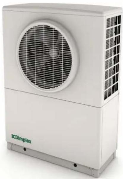
natural_image
Exterior view of a white industrial air conditioning unit with fan grille and ventilation grille (no visible text or symbols)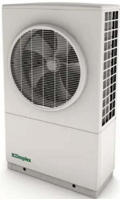
natural_image
Exterior view of a white industrial air conditioning unit with fan blades and grid-patterned panel (no visible text or symbols)Table of Contents
Overview - Air to Water Heat Pump 1
1 Introduction 5
1.1 Scope of Delivery 5
1.2 Safety Warnings 6
1.2.1 Handling and Transport 6
1.2.2 General 6
1.2.3 Safety 6
1.2.4 Maintenance 7
1.2.5 Electrical Warnings 7
1.2.6 Intended Use 7
1.2.7 Legal 8
1.2.8 Connection to the Grid - Notifying the DNO (Distribution Network Operator) 8
1.2.9 Heat Pump Sizing 8
2 Preparation 9
2.1 Site Selection 9
2.1.1 Location of Heat Pump 9
2.1.2 Location of Indoor Components 9
2.1.3 Heat Pump Placement and Fixing 10
3 Installation 12
3.1 Plumbing Information 12
3.1.1 Pipe Sizing Information 12
3.1.2 Buffer Tank 13
3.1.3 Metering for the Domestic Renewable Heat Incentive 13
3.2 Plumbing - Installation 14
3.3 Electrical Information 14
3.3.1 Access to Electrical Connections - Opening the Heat Pump 17
3.3.2 Electrical Connections - Power and Communication Cable Heat Pump Connections 18
3.3.3 Modbus Cable Information 20
3.3.4 Opening and Installing the User Interface 20
4 Heat Pump Controller / Commissioning 21
4.1 Set to Work 21
4.1.1 Starting the Heat Pump in Cold Weather 21
4.1.2 Bivalent Mode (Alternative Back-Up Heat Sources) 22
4.1.3 Operating Modes 22
4.2 Commissioning 23
4.2.1 Waterside Check 24
Table of Contents
4.2.2 Temperature Check 24
4.2.3 Electrical Connections (SH) 25
4.2.4 Water Flow Check 25
4.2.5 DHW Setup 26
4.2.6 Electrical Connections (DHW) 26
4.2.7 DHW Test 27
4.2.8 Disinfection (Thermal) 29
4.2.9 Weather Compensation 29
4.2.10 Heating Curves 29
4.2.11 Comfort Level 30
4.3 Additional Installer Menu Options 31
4.3.1 Message Log 31
4.3.2 Output Tests 31
4.3.3 Defrost 32
4.3.4 Operating Data 32
4.3.5 History 32
4.3.6 Service Menu 32
5 System Health Check / Maintenance 33
APPENDICES 34
A - Technical Specifications 35
B - Refrigeration Cycle diagram 36
C - Schematic Zone Diagrams - Legend 37
D - Schematics 1, 2, 3 & 4 : Space Heating Only 38
E - Schematics 5, 6, 7 & 8 : Zone Space Heating & Domestic Hot Water 39
F - Schematics 9, 10, 11 & 12 : Bivalent Space Heating 40
G - Schematics 13, 14, 15 & 16 : Bivalent Zone Space Heating & Domestic Hot Water 41
H - Wiring Centre Electrical Connections - with A-Class Cylinder 42
I - Jumper Information for Alternative Wiring Configuration 43
J - Controller Cable Connection's 44
K - Installer Menu Flow Chart 45
Installer Hand-Over Form 46
Certificate of Conformity 47
Overview - Air to Water Heat Pump
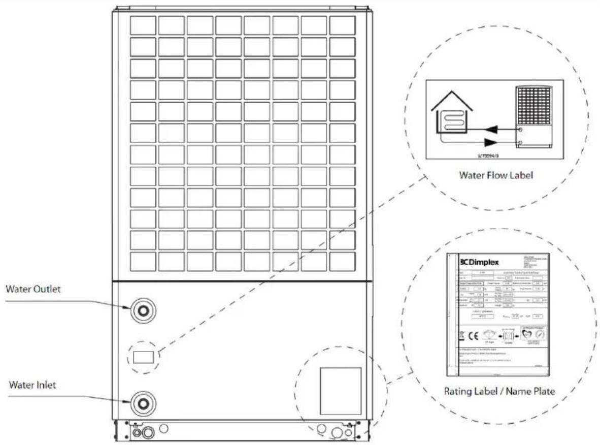
Figure 1(a): Connection and label locations and details
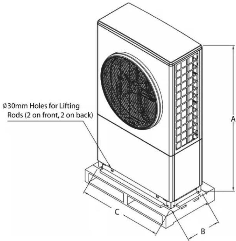
| Model A B C | |||
| A8M 1260mm | 400mm 930mm | ||
| A12M / A16M | 1571mm 400mm 930mm |
Volume of 8kW Heat Pump = 0.47m ^3
Volume of 12/16kW Heat Pump = 0.59m ^3
Figure 1(b): Lifting rod hole positions and heat pump external dimensions
Pack 1 - Space Heating and Dimplex A-Class Cylinder
| A Class Heat pump A8M / A12M / A16M | 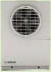 | |
| Hydraulics Kit A which includes: | ACCHYPK | |
| User interface (UI) | 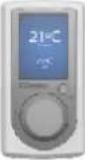 | 1754600 |
| Pump - UPM GEO 25-85 180 (1500mm cable) 1755740 |  | |
| 2 x Circulation Pump Gate Valve 1^1/2 "swivel to 28mm comp2 x Washer 30.1x21x2mm |  3090 3090 | |
| ERES straight Spring loaded by-pass valve(22mm comp fitting) | 1755780  | |
| 3 port diverting valve (28mm comp. fittings) 1755750 | 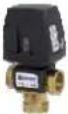 | |
| Isolation valves (1" swivel BSP to 28mm comp)(1) Flow(2) Return with strainer |  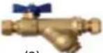 (1) (2) (1) (2) | Flow 1755760Return 1755770 |
| 4 x Blanking plugs for lifting holes 4592624105 | ||
| Installation and User manuals/instructions |   | Installation: 8/60472/0User: 8/60476/0 |
| Dimplex A Class DHW Cylinder Kit which includes: | ||
| A Class Cylinder with integrated buffer |  | |
| Air vent |  | |
| Drain |  | |
| Safety group DHW side;expansion vessel, hose and bracket, inlet group, tundish | 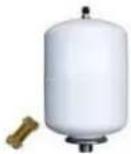 | |
| 3 x Copper pipes – Pump to buffer/cylinder |  | |
| Pipe connections to coil, pipe, drain and vent, Pipe connections to pump | ||
| Pack 2 - Space Heating and Dimplex A-Class Cylinder | ||
| A Class Heat pump A8M / A12M / A16M | 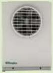 | |
| Hydraulics Kit A which includes: ACCHYPK | ||
| User interface (UI) | 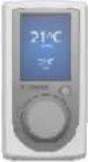 | 1754600 |
| Pump - UPM GEO 25-85 180 (1500mm cable) 1755740 |  | |
| 2 x Circulation Pump Gate Valve 1^1/2 "swivel to 28mm comp2 x Washer 30.1x21x2mm |  090 090 | |
| ERES straight Spring loaded by-pass valve(22mm comp fitting) | 1755780  | |
| 3 port diverting valve (28mm comp. fittings) 1755750 | 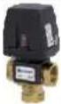 | |
| Isolation valves (1" swivel BSP to 28mm comp)(1) Flow(2) Return with strainer | 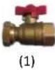 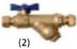 | Flow 1755760Return 1755770 |
| 4 x Blanking plugs for lifting holes 4592624105 | [003C] | |
| Installation and User manuals/instructions |   | Installation: 8/60472/0User: 8/60476/0 |
| Wiring centre kit which includes: | ||
| Wiring centre module | 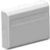 | 049162 |
| (including 1 x Temperature probe (NTC10) for DHW) |  | |
| Dimplex Standard Cylinder | 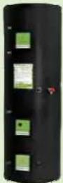 | |
NOTE: CYLINDER REQUIRED FOR PACK 2 INSTALLATION, PLEASE SEE DIMPLEX EC-EAU CYLINDER MANUAL FOR RANGE OF NON A-CLASS CYLINDERS AVAILABLE.
| Pack 3 - Space Heating Only | ||
| A Class Heat pump A8M / A12M / A16M | 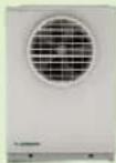 | |
| Hydraulics Kit B which includes: ACCHYPK | ||
| User interface (UI) | 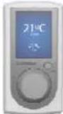 | 1754600 |
| Pump - UPM GEO 25-85 180 (1500mm cable) 1755740 |  | |
| 2 x Circulation Pump Gate Valve 1^1/2 "swivel to 28mm comp2 x Washer 30.1x21x2mm | 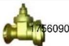 | |
| 3 port diverting valve (28mm comp. fittings) 1755750 | 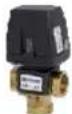 | |
| Isolation valves (1" swivel BSP to 28mm comp)(1) Flow(2) Return with strainer |  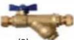 (1) (2) (1) (2) | Flow 1755760Return 1755770 |
| 4 x Blanking plugs for lifting holes 4592624105 | [IMAGE] | |
| Installation and User manuals/instructions |   | Installation: 8/60472/0User: 8/60476/0 |
| Wiring centre kit which includes: | ||
| Wiring centre module | 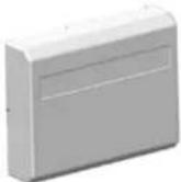 | 049162 |
| (including 1 x Temperature probe (NTC10) for DHW) |  | |
| Accessories | ||
| 100L/200L/300L Buffer tank(depending on installation) | 02558 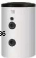 | |
| 2kW buffer immersion element 363610 |  | |
1 Introduction
Thank you for choosing a Dimplex Heat Pump. The Dimplex A-Class heat pump provides outstanding performance to maximise year-round efficiency, regardless of the weather conditions. It can deliver high output and high temperatures even at low outside air temperatures of -7^ . The sophisticated controller makes the system easy to use and there are many more technological innovations including a scroll compressor that uses enhanced vapour injection.
1.1 Scope of Delivery
Please ensure you check the scope of delivery before signing any delivery documentation. Below is a guideline checklist for what should be contained in each pack. Claims for missing or damaged parts after signing for the delivery will not be accepted.
There are 3 options to select from when installing a Dimplex Heat Pump:
Pack 1 - Space heating and Dimplex A-Class Cylinder
— This pack should contain four boxes;
Heat Pump
◆ ACCHYPK Hydraulics Kit A (contains all of the necessary hydraulic components)
♦ Cylinder
◆ Cylinder Accessories
— A separate wiring centre is not required as the wiring centre is built into the cylinder.
Pack 2 - Space heating and Dimplex Standard Heat Pump Cylinder
— This pack should contain five boxes;
Heat Pump
◆ ACCHYPK Hydraulics Kit A (contains all of the necessary hydraulic components)
♦ Cylinder
◆ Cylinder Accessories
♦ Wiring Centre
— A separate wiring centre is required as the wiring centre is not built into the standard cylinder.
Pack 3 – Space heating only
- This pack should contain three boxes;
Heat Pump
◆ ACCHYPK Hydraulics Kit B (contains all of the necessary hydraulic components)
♦ Wiring Centre
Accessories
— A separate wiring centre is required to wire the circulation pumps and controls.
Details of all packs/components provided are shown on pages 2-4 of this manual.

1.2 Safety Warnings
1.2.1 H ANDLING AND TRANSPORT
- When transporting, moving and installing the heat pump, ensure that it is not tilted by more than 45^ (in any direction), for any prolonged period of time (see figure 2).
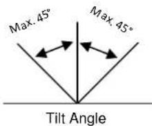
Figure 2: Allowable tilt angle during handling
- Do not attempt to lift the heat pump manually, as it weighs 110-130kg and should only be lifted using the appropriate lifting devices.
- Ensure that there is a clear pathway for a truck to deliver the heat pump as close to the selected location as possible.
- The installer must use a suitable lifting method, in accordance with health and safety regulations.
- Straps must also be used with lifting rods to prevent the heat pump from toppling.
1.2.2 GENERAL
- Installation and any service work on the heat pump may only be performed by an authorised and qualified installer and after-sales service technicians.
- Additional heating may be required if the heat pump is intended to dry out a new or renovated building, as the initial heat load may be higher than the design load.
- Products not installed with the Dimplex hydraulics packs will not be supported by Dimplex. This includes but is not limited to thermal stores.
- All information and instructions regarding how the device is fixed to its supporting plinth can be found in section 2.1.3 of this installation manual.
1.2.3 SAFETY
- The heat pump contains refrigerant at high pressure. Safety measures are in place to avoid system pressure build up.
- Stage 1: Pressure transducer stops compressor.
- Stage 2: Pressure switch switches heat pump off. All safety devices reset automatically.
- The heat pump has a multi-layered, software generated alarm management system, which prevents it from running outside its operating limits. If an alarm / message occurs, the heat pump will attempt to take remedial action before causing the system to stop completely if the problem persists. However, the overriding safety feature is the high pressure switch, which de-energises the main contactor supplying power, in accordance with EN378.
- This appliance can be used by children aged from 8 years and above and persons with reduced physical, sensory or mental capabilities or lack of experience and knowledge if they have been given supervision or instruction concerning use of the appliance in a safe way and understand the hazards involved. Children shall not play with the appliance. Cleaning and user maintenance shall not be made by children without supervision.
1.2.4 MAINTENANCE
- If the heat pump may be disconnected from the power supply for prolonged periods of time, or where power supplies are susceptible to failure, antifreeze must be added to the system (e.g. mono ethylene glycol at 25% volume to protect down to -14°C).
- Never use cleaning agents containing sand, soda, acid or chloride as these can damage surfaces/components.
- We recommend the installation of a suitable filtration protection system and the use of a corrosion additive for the heating system to prevent the formation of deposits (e.g. oxide and solids) in the condenser of the heat pump. The return isolation valve provided in the hydraulics pack has a built in strainer to help prevent debris entering the condenser and must be fitted.

E
LECTRICAL WARNINGS
- Before removing the cover of the heat pump, cylinder or wiring centre, ensure that all electrical circuits are isolated.
- Means for disconnection from the supply mains must be incorporated into the fixed wiring in accordance with the national wiring regulations.
- This device must be installed in accordance with national wiring regulations.
- This device is suitable for mains connection only (230V, 1P&N, 50Hz) and is not suitable for operation with an electrical generator or power modulator, due to possible effects on the quality of the electrical supply. Any attempt to do so will void warranty.
- The local wiring regulations should always be followed paying particular attention to the mixing of low voltage and extra low voltage cabling.
- Ensure the incoming power supply and the distribution board are suitably rated.
- Ensure that the regulations specified by the local electricity supplier have been adhered to.
- All fuse rating and protective overload device information is provided in the wiring label located on the inside of the front bottom panel of the heat pump. For instruction on how to remove this panel please see section 3.3.1.
• The correct earthing (grounding) of the heat pump is of the utmost importance and must be reinforced by
- Using an earth (ground) wire of at least 10mm^2 , OR;
- Using two separate earth (ground) wires, both complying with the dimensioning rules as set out by local and national regulations.

NOTE: THE INSTALLATION OF A HEAT PUMP DESIGNATED RESIDUAL CURRENT DEVICE (TYPE B RCD) HAVING A RATED RESIDUAL OPERATING CURRENT NOT EXCEEDING 30mA IS RECOMMENDED, IN ACCORDANCE WITH LOCAL REGULATIONS (BS7671 FOR UKINSTALLATIONS).

NOTE: TWO SEPARATE, DESIGNATED RCD DEVICES SHOULD BE FITTED - ONE FOR THE HEAT PUMP AND ONE FOR THE CYLINDER. THE HEAT PUMP SYSTEM MUST NOT SHARE AN ALREADY EXISTING DOMESTIC RCD DEVICE.

NOTE: THE HEAT PUMP HAS A HIGH LEAKAGE CURRENT AND MUST BE PROPERLY GROUNDED FOR SAFETY IN ACCORDANCE WITH LOCAL AND NATIONAL REGULATIONS REGARDING EQUIPMENT WITH A LEAKAGE CURRENT EXCEEDING 3.5mA.
1.2.6 INTENDED USE
This product is designed to extract heat from outside air to provide energy for a water-based heating system, and is intended for domestic and light commercial use. Any other use beyond that intended by the manufacturer is prohibited. This requires the user to abide by the manufacturer's product information. Please refrain from tampering with or altering the device.
1.2.7 LEGAL
The construction and design of the heat pump complies with all relevant EU directives (see CE declaration of conformity in appendix section).
When connecting the heat pump to the power supply, the relevant EN and IEC standards must be adhered to. Any further connection requirements stipulated by the network operation must also be observed.
When connecting to the heating system all applicable regulations must also be adhered to.

C
ONNECTION TO THE GRID - NOTIFYING THE DNO (DISTRIBUTION NETWORK OPERATOR)
Before you connect a heat pump to the grid, the necessary permissions must be granted by the distribution network operator. Not obtaining the necessary permissions may result in an unexpected network upgrade charge, and may compromise the integrity of the local supply if a 'disturbing load' is connected to the network.
The required forms are supplied by Dimplex and must be filled in by the heat pump installer alongside the client. We recommend notifying the DNO as early as possible in the planning stage to discuss the project and any additional information. Further information can be found on the Energy Networks website (www.energynetworks.org) or from your local DNO.
1.2.9 H EAT PUMP SIZING
- Ensure that the correct size heat pump has been selected in accordance with the latest version of MIS3005 (for UK installations).
- If a non A-Class heat pump cylinder is being used, ensure that it has been accurately sized with the appropriate coil surface area of the cylinder to match the heat pump's output and flow rate requirements, and that all necessary hydraulic connections have been considered in connecting it to the heat pump system.
- Ensure that suitable heat emitters have been sized in accordance with the Heat Emitter Guide (for UK installation) and selected ensuring a low flow temperature design. To maximise system efficiency it is important to design the system with the lowest flow temperature possible.
2 Preparation
2.1 Site Selection
2.1.1 LOCATION OF HEAT PUMP
- The heat pump must be installed outdoors with adequate clearances for ventilation and maintenance. It is recommended that the heat pump is installed along the property wall, as shown in figure 3.
• There must be a minimum distance of 1m in front of the fan to prevent air re-circulation. - Positioning the heat pump in a confined space, frost hollow or well will result in reduced heat pump efficiency, as the cold air which is expelled by the fan cannot disperse and may be drawn back into the system. This means that the heat pump may be operating using a lower inlet temperature than what is actually available from the surrounding ambient air, and will therefore run less efficiently.
- The fan should preferably not face prevailing winds to ensure correct air flow through the evaporator.
- Although the heat pump is within noise and vibration regulations outlined in MCS007, it is recommended to avoid positioning it close to bedroom windows, as the fan and compressor may be operational at night.
2.1.2 LOCATION OF INDOOR COMPONENTS
The controller/user interface that is supplied with the Dimplex A-Class heat pump is used as a heat pump controller as well as a heating and domestic hot water (DHW) controller. It is also the preferred option for use as a room temperature control device. The user interface and room thermostats should be installed indoors in a location that is out of reach of children, but where the LCD display can be easily seen (usually 1.2m – 1.7m from the floor).
While only one user interface is currently available per system, there are additional options of either temperature probes or mechanical thermostats, which can be used to control the temperature in up to four zones. Mechanical thermostats provide less control over the heating system, while the temperature probe option allows the heat pump to sense changes in demand and adjust accordingly. The temperature probe option is generally recommended over the mechanical thermostat option.
A zone is defined as the physical area of the home in which temperatures are controlled by each individual device. For example, there might be a user interface installed in the living area, in which case this may be referred to as zone 1. There may also be a temperature probe installed upstairs in the sleeping/bedroom area, which would then be designated as zone 2, and so on. Extra zones are an additional, optional feature of the heating system. The standard package comes with one User Interface and the possibility of four separate zones.
The controller and thermostats should be installed on internal walls in living area to reflect the correct temperature, and away from direct sunlight, drafts (windows and doors) and heat emitters.
LOCATION OF WIRING CENTRE
If a Dimplex A-Class cylinder is used, the wiring centre is built in and pre-wired. If a non A-Class cylinder is used, the wiring centre module must be installed. The wiring centre module is designed to be wall mounted, and it is recommended that it is installed in close proximity to the cylinder to allow for installation of components which require a control cable (modbus) connection, i.e. pump, DHW probe, 3-port valve and heat pump connections.
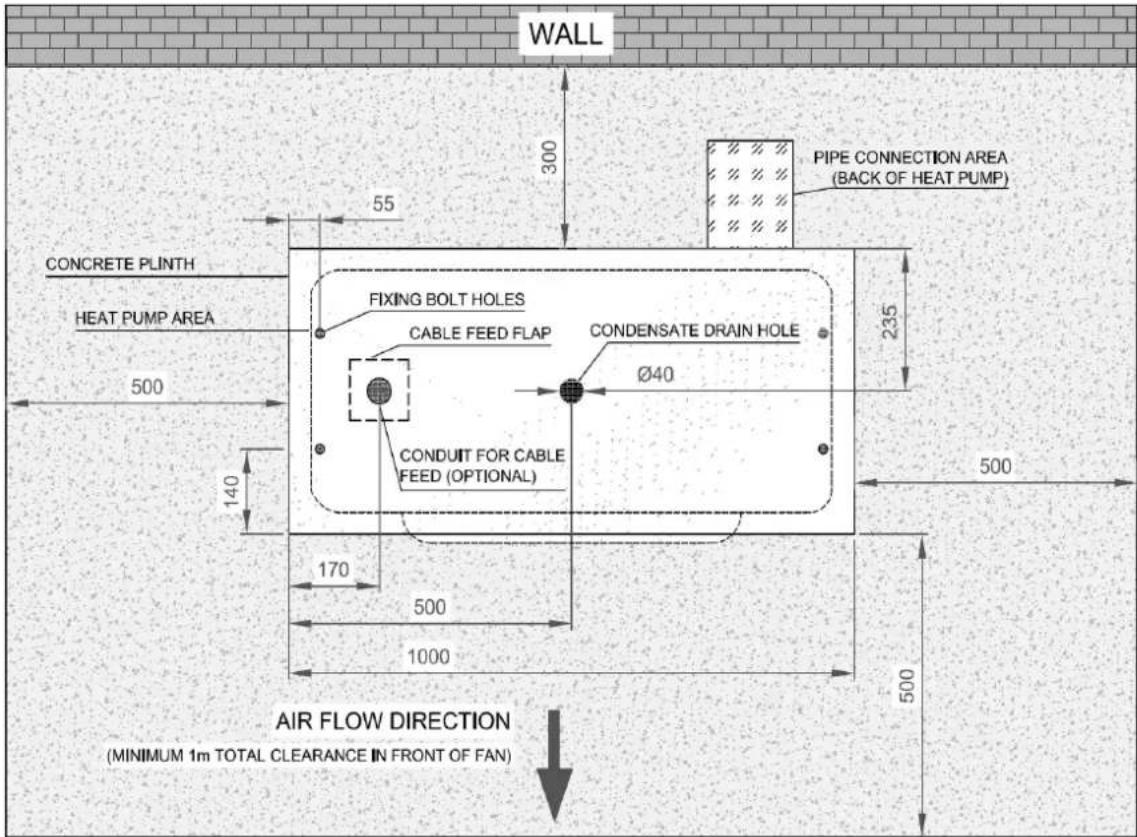
Figure 3: Suggested heat pump layout and minimum access and air flow clearance dimensions (in mm)
2.1.3 H EAT PUMP PLACEMENT AND FIXING
- Approximately 2 litres of condensate water are drained from the system every time a defrost cycle occurs (approximately once every hour in cold and humid weather). Therefore, it is essential that the condensate pipe is fed into a drain or soak away to allow for safe disposal of the excess water, away from footpaths or patios.
- The condensate drain pipe is coiled up inside the heat pump for protection during transportation. In order to access this for installation, the panels will need to be removed (see section 3.3.1).
- The removal of condensate must be secured and the condensate pipe must be kept free from debris and frost. The pipe should be prevented from exposure to the elements, as this may contribute to freezing issues. Freezing of this pipe due to incorrect installation can result in irreparable damage and void warranty.
- The condensate pipe should not run into sewer pipe unless a suitable trap is installed, as fumes may travel into the heat pump and cause corrosion to the evaporator coil.
-
The heat pump must be fixed onto a level, stable base that is capable of withstanding the unit's weight of 110-130kg (depending on model), with a minimum distance of 50mm around all sides of the heat pump. It can be secured on the inside of the heat pump with M10 anchor bolts, by removing the outer panels and using the fixing holes shown in figure 3.
-
The positions of the fixing holes can be located by placing the heat pump on the plinth with the condensate pipe aligned, and marking the holes. Move or slide the heat pump to drill holes.
- Ideally the heat pump should be located close to the property. Positioning of the heat pump away from the property will result in the need for extra insulated pipe, which will lead to extra cost, and result in additional heat losses.
- In figure 3, there are four fixing holes ∅16mm (centre 140mm from long edge, 55mm from short edge and 190mm from centre to centre for each pair) and one centre hole for the condensate pipe. The minimum recommended plinth dimensions are 1000mm x 470mm x 100mm.
- The minimum clearance distances around the heat pump are shown in figure 3; 300mm at the rear for air flow, 500mm each side for service and at least 1000mm in front of the fan to avoid air recirculation.
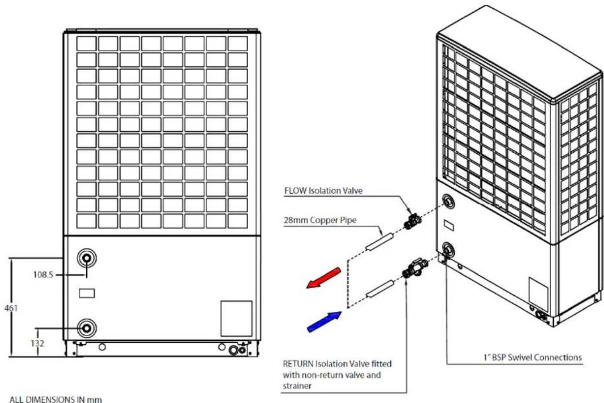
Figure 4: Details of flow and return isolation valves
3 Installation
3.1 Plumbing Information
3.1.1 P IPE SIZING INFORMATION
When selecting piping to install with the heat pump please ensure that:
- The pipe sizes are adequate to allow the correct nominal water flow rate through the heat pump.
- The safety group and expansion vessel (space heating side) are accurately sized by the installer based on the system volume (these are not supplied by Dimplex).
- External pipework and valves should be adequately insulated with vapour resistant insulation and protected against damage to prevent excessive heat losses. All joints should be suitably sealed and exposed pipework must be avoided.
- Existing hot water systems should be flushed prior to connection to the heat pump to remove all contaminants and impurities, in accordance with the latest version of MIS3005. Ensure the water out and water in pipes are positioned correctly for connection to the heat pump as shown on the label in figure 1(a) and on the back of the heat pump in figure 4.
- Isolation valves (non-return valve and ball valve with strainer), supplied in the Dimplex heat pump hydraulics pack, allow the strainer to be removed and cleaned without having to drain the system. Installation of these valves is discussed in greater detail in section 3.2.
- If multiple heat emitter circuits are installed, operating at different flow and return temperatures (such as under floor heating and standard radiators), a mixing valve must be used on low temperature circuits to prevent high temperature water from entering the under floor heating manifold.
Table 1 shows guidelines for the maximum length of pipe allowed to achieve nominal flow rates, depending on pipe diameter. This table is only valid when using the pump supplied in the Dimplex hydraulic kit (see pages 2-4).

NOTE: THE HYDRAULIC INSTALLATION INFORMATION PROVIDED IN THIS MANUAL APPLIES ONLY TO THE COMPONENTS PROVIDED IN THE GLEN DIMPLEX HYDRAULICS PACK (SEE PAGES 2-4 FOR PACK INFORMATION).
| A8M | A12M / A16M | |||
| Space Heating Only | Space Heating Only | DHW with A-Class Cylinder | ||
| Water Flow Rate @ 1100 l/h (nominal) @ 2100 l/h (nominal) @ 1800 l/h (typical) | ||||
| Associated Head Available | 60kPa | 14 kPa | 18kPa | |
| Pipe Diameter (mm) | Internal Diameter (mm) | Maximum Equivalent Length (m)~ | ||
| 15* | 12.0 | 8 | N/A | N/A |
| 22* | 19.8 | 90 | 7 | 11 |
| 28^ | 25.6 | 300 | 23 | 38 |
| 32^ | 29.6 | 600 | 46 | 77 |
Table 1: Maximum Equivalent Length for Copper Pipe - Water ONLY
*Only suitable for special conditions ^Recommended pipe diameter for A12M/A16M
Assuming straight length with no incidents
(e.g. elbows, tees)

NOTE: NOT ALL TYPES OF PIPE WILL HAVE THE SAME INTERNAL DIAMETER, E.G. MULTI-LAYERED/PLASTIC PIPES WILL HAVE A THICKER WALL SO THE GUIDELINES SET OUT IN TABLE 1 WILL NOT APPLY. MICROBORE (8mm) AND 15mm PIPE IS NOT SUITABLE.
AS A RULE OF THUMB, THE EQUIVALENT STRAIGHT LENGTH (L [mm]) OF EACH ELBOW IS FOUND BY MULTIPLYING THE OUTER DIAMETER OF THE PIPE (D [mm]) BY 30, E.G. 4 ELBOWS OF DIAMETER 22mm PIPE IS EQUIVALENT TO 2.5m OF 22mm PIPE.

NOTE: TABLE 1 ABOVE IS PROVIDED AS A GUIDELINE WHEN USING WATER ONLY. ANY PERCENTAGE OF ANTI-FREEZE ADDED WILL AFFECT THE PRESSURE DROP OF THE SYSTEM GREATLY AND WILL RENDER THIS TABLE INVALID.
3.1.2 BUFFER TANK
The heat pump uses a reverse cycle defrost in order to defrost the evaporator by taking heat from the heating system. It is therefore necessary to connect a buffer tank in series with the heat pump, as shown in the hydraulic schematic diagrams (Appendix D - G). The Dimplex A-Class cylinder range come with an integrated buffer tank, which;
• Provides some energy storage for the unit to carry out successful defrost.
• Increases compressor life due to reduction in the number of starts.
It is recommended that a buffer with a heating element/immersion is used as it may be required if initial start-up and commissioning are carried out in very cold weather.
Buffer Tank Sizing
For installations using Smartrads/radiators, the minimum total system water volume should be no less than 100l, although 200l is preferred. For installations with a poor water flow rate, a larger buffer would be beneficial.
For a system with underfloor heating (UFH), the 40l buffer built into the A Class cylinder should be sufficient as the UFH will provide enough thermal mass to limit the drop in temperature over defrost duration (provided that one zone is always open).
3.1.3 M ETERING FOR THE DOMESTIC RENEWABLE HEAT INCENTIVE - UK
Please take note of the following requirements if the installation is to be fitted with a meter;
- Leave sufficient space for appropriate meters to be fitted in defined locations.
- For Dimplex installations using 22mm pipe, please leave 440mm of straight pipework on the meter inlet pipe and 175mm of straight pipework on the outlet pipe;
- For installations using 28mm pipe, please leave 560mm of straight pipework on the meter inlet pipe and 175mm of straight pipework on the outlet pipe.
- Install low pressure-drop isolation valves to avoid the need to drain systems when fitting heat meters. See the schematics (Appendix D-G) for more information on valve locations.
- Leave sufficient pipework accessible, i.e. not boxed in or under floor boards, to enable meters to be fitted.
Guidelines for fitting an MCS approved meter can be found in the Domestic Renewable Heat Incentive essential guide to metering, available on the Ofgem website: www.ofgem.gov.uk
3.2 Plumbing - Installation
- The system must be filled and flushed with clean fresh water to ensure the removal of all the air from the installation. Air bleed points must be installed at the highest point in the system; in particular, the installer must remember to install an air bleed on the heat pump pipe if it is a local high point since there is no air bleed point on the heat pump itself. Dimplex recommend the use of a power flush and purge cart to facilitate this process.
- Flow and return isolation valves and piping must be fitted to each of the heat pump water connections on the back of the heat pump, as shown in figure 4.
- The isolation valve on the return is also fitted with a non-return valve and a strainer (included in the Dimplex heat pump hydraulics pack). This means that in order to clean the strainer, the system does not have to be drained. Instead, it is possible just to close the isolation valves on the return and remove the strainer. This way, the only water that will be lost from the system is that between the non-return valve and strainer.
- The strainer must be fitted in order to prevent contamination of the condenser heat exchanger. If an alternative strainer is used, it must be at least 7 microns in size.
• System should be pressurised and the system pressure must be checked once valves are re-opened.
• Direct condensate drain pipe to soak away or drain.
• All piping must be properly insulated and external length kept to a minimum.
Adjusting the By-Pass Valve
The bypass valve is used to maintain a minimum flow rate and prevents faulty operation of the heat pump, as well as allowing it to run efficiently. The bypass valve must be adjusted correctly after commissioning the heat pump.
Please ensure that the following steps are taken when adjusting the bypass valve;
- Ensure that the bypass valve is open fully and begin running the heat pump.
- Close all of the heating circuits that may be closed during the operation of the heating system so that the least favourable flow rate can be achieved. This should cause all of the flow to go through the bypass valve. To check that all of the water flow is going through the bypass valve, feel the pipe after the valve to check its temperature (it should be getting heat from the heat pump).
- Slowly close the valve until the water is no longer flowing through it, then turn the valve back slightly (approx. 0.5 to 1 turn) to allow some flow and prevent the heat pump from tripping.
- Open the zone valves while the heat pump is still running, and again check the flow through the bypass valve by feeling the pipe after the valve and checking its temperature (it should not be as hot as flow temperature). The bypass setting should allow hot water to flow through the bypass valve when some of the heating circuits are closed.
3.3 Electrical Information
The heat pump system consists of the heat pump, wiring centre and user interface. If a Dimplex A-Class cylinder is also used, the wiring centre is built into the cylinder.
The user interface acts as a thermostat and is sufficient if one heating zone is present. Optional, additional temperature probes or room thermostats are required for additional heating zones.
Figures 5 & 6 show the different possible wiring configurations for systems with and without a Dimplex A-Class cylinder.
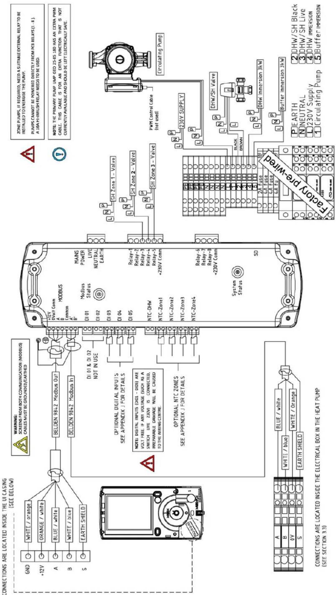
Figure 5: Wiring centre electrical configurations - with non A Class cylinder / no cylinder
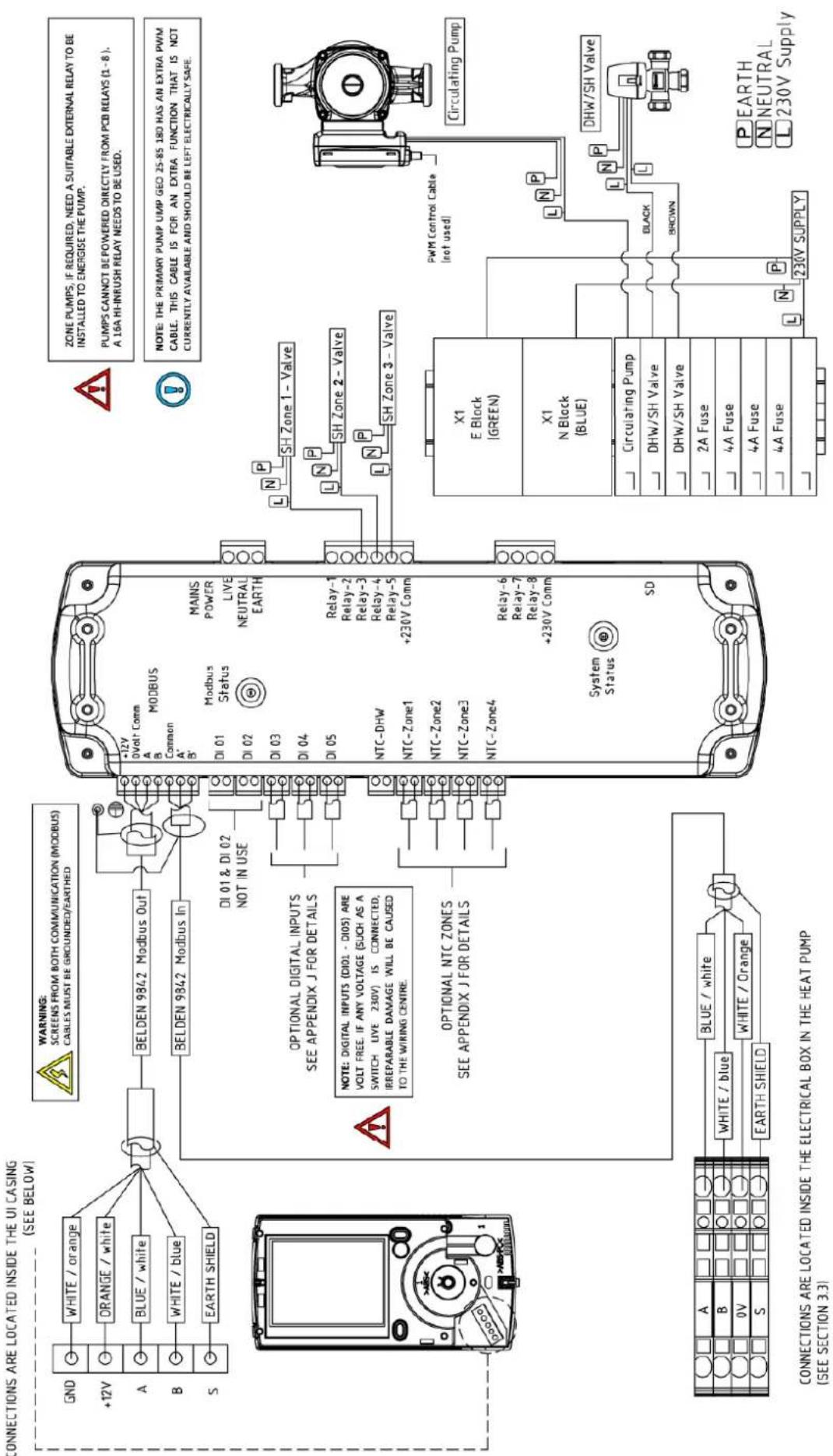
Figure 6: Wiring centre electrical configurations - with A Class cylinder
Warnings
• Before opening the heat pump, ensure all circuits are isolated.
• Ensure that the components in the electrical box do not get wet when the electrical box is opened.
• The main 230V power cable must be supplied via a suitable sized exterior isolator, lockable in the OFF position.
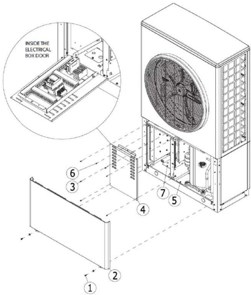
Figure 7: Opening the casing to fit electrical connections
3.3.1 A CCESS TO ELECTRICAL CONNECTIONS - OPENING THE HEAT PUMP
To open the heat pump, follow the procedure shown in figure 7;
- Unscrew 2 screws (1) holding front bottom panel (2) using a PZ2 screwdriver
- Pull the front bottom panel (2) down then out to remove
- Unscrew 5 screws (3) holding the front cover (4) of the electrical box to open and then pull down
- Remove 2 PZ2 screws (6) holding the door flap in place to access cable connections.
(Note: cable access cover (7) only used on some models. For model cable connection configurations for your heat pump model, please see figure 9(a) and 9(b)).
- The cable access covers (5 and 7) can be opened by removing a screw to allow access to cables.
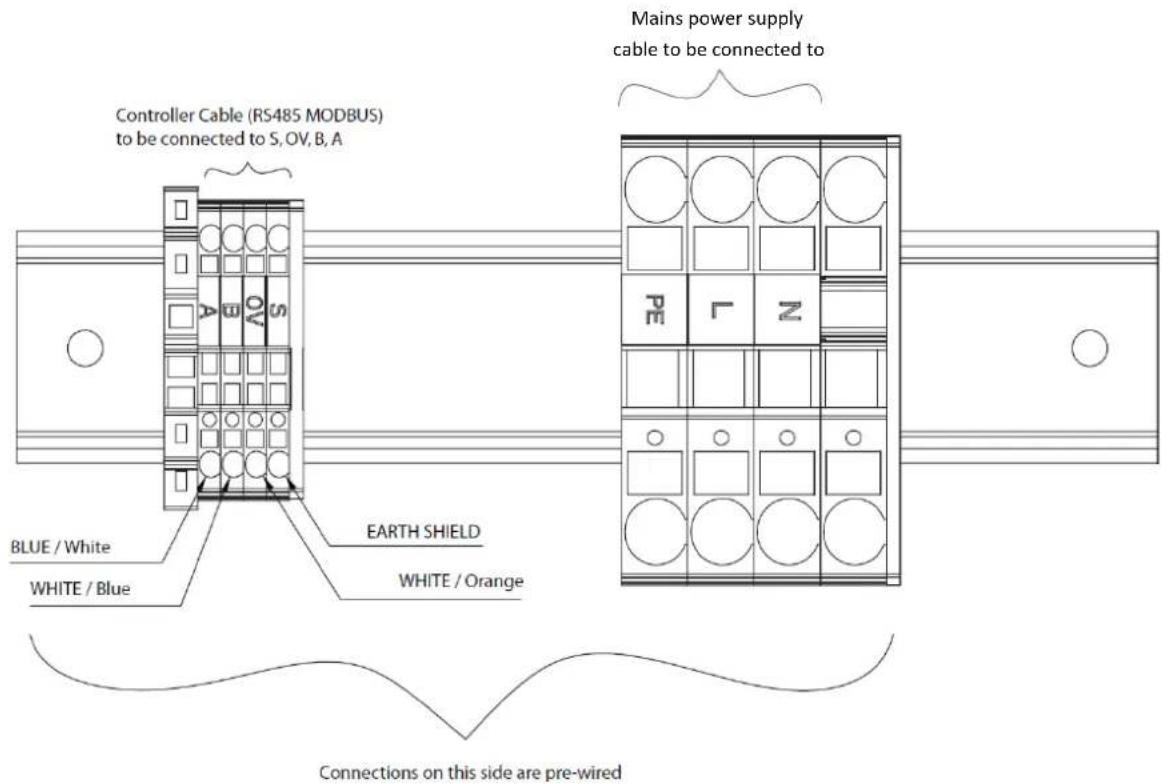
Figure 8: Heat pump electrical connections

NOTE: 'S' AS SHOWN IN FIGURE 8 ABOVE IS THE EARTH SHIELD AND MUST BE CONNECTED DURING INSTALLATION.

NOTE: ENSURE THAT CABLE ACCESS COVERS ARE CLOSED CORRECTLY WHEN NOT IN USE.

NOTE: FOLLOW STEPS IN REVERSE ORDER TO CLOSE THE HEAT PUMP. WHEN CLOSING THE HEAT PUMP FRONT PANEL, ENSURE THAT THE TOP AND BOTTOM PANELS ARE INTERLOCKED.
3.3.2 ELECTRICAL CONNECTIONS - POWER AND COMMUNICATION CABLEHEAT PUMP CONNECTIONS
The electrical connections to the heat pump may have one of two configurations, depending on the model. Please see diagrams 9(a) or (b) for your configuration.
For configuration 1, the cables are fed through the holes at the back of the heat pump and directly inside the electrical box through the base of the heat pump (see figure 9(a)).
For configuration 2, the cables are fed through the holes at the back of the heat pump, up through the holes in the base of the heat pump and then from outside the electrical box through the cable glands (see figure 9(b)).
- Allow sufficient cable length to ensure the connections are not strained when the cover is opened.
• Once cables have been routed through the cable glands, close the access cover. - Connect power cable and controller cable as shown in figure 8. Do not strip the cables before pulling them through the glands in the access panel. Where stranded cable is being used, a ferrule must be fitted before inserting into the push connections.
- The controller (Modbus) cable is then connected from the heat pump to the wiring centre (see wiring diagrams in figures 5 & 6).
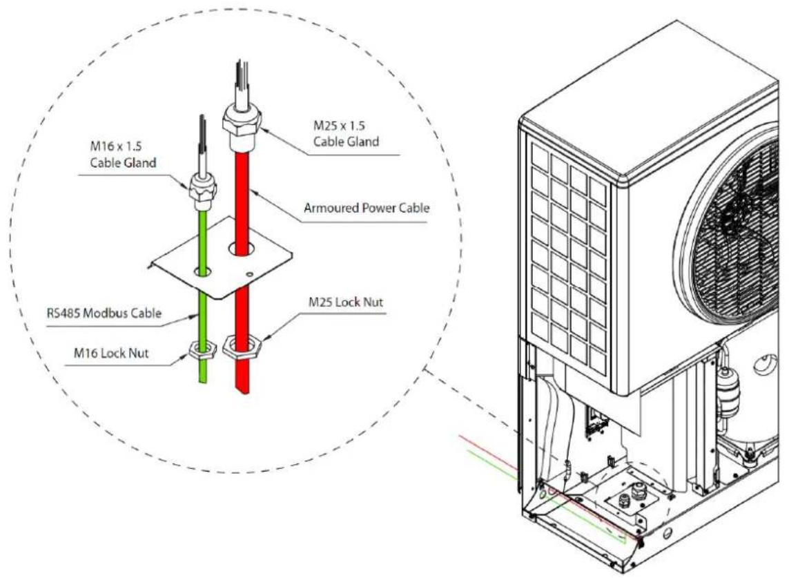
Figure 9(a): Heat pump electrical connections - configuration 1
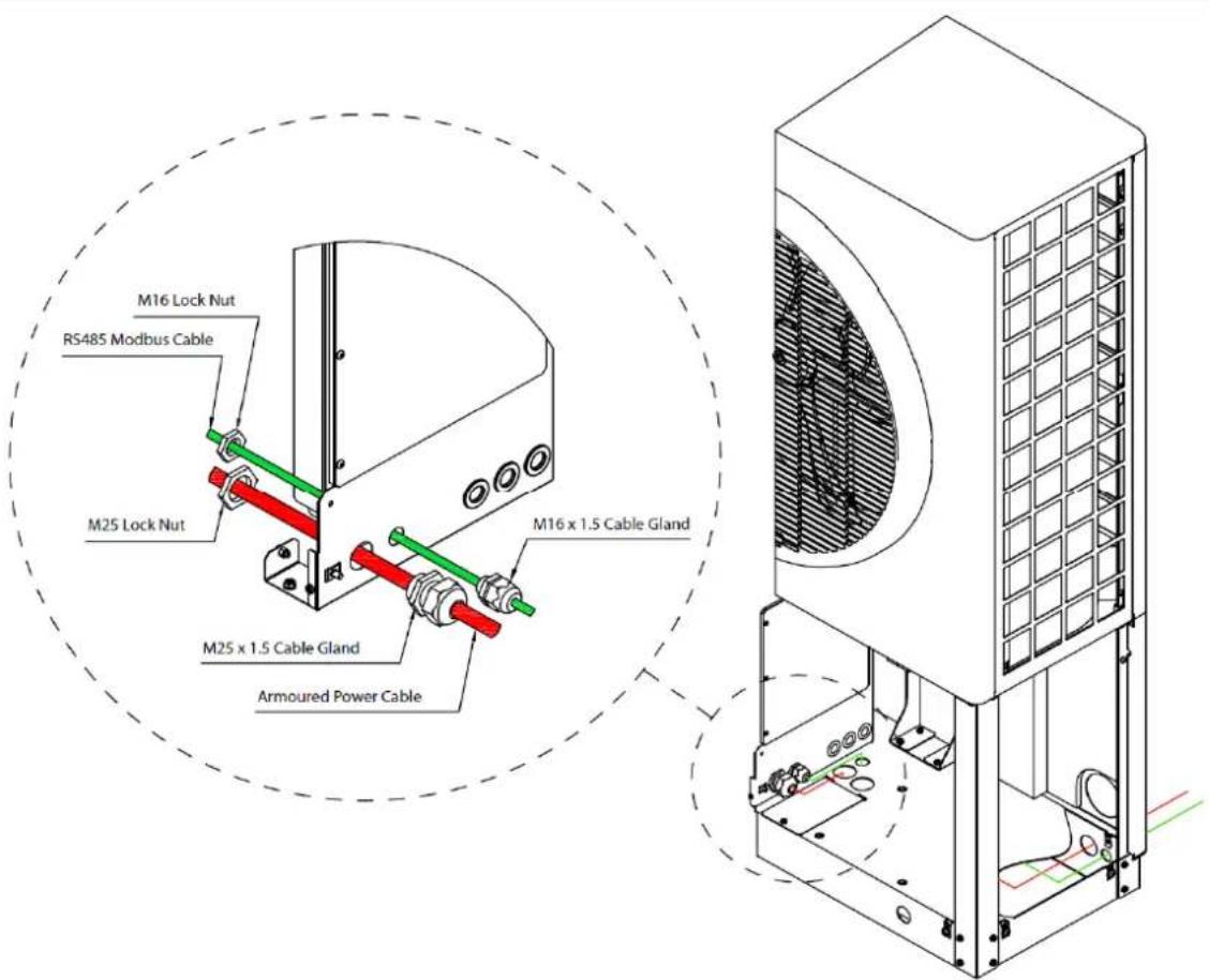
Figure 9(b): Heat pump electrical connections - configuration 2
3.3.3 MODBUS CABLE INFORMATION
| Belden Cable 9842 Typical Equivalent Cable | ||
| Nominal Characteristic Impedance | 120Ω 120Ω | |
| Nominal Conductor DC Resistance | 24.0Ω /1000ft78.7401 Ω/km* | 78.80 Ω/km* |
| Nominal Capacitance Core to Core | 12.8pF/ft41.99pF/m | 42pF/m |
| *Conversion factor for ft to m = 3.28 ft = 1m1km of Belden cable would have a resistance of 78.74 Ω/km1km of Equivalent cable has a resistance of 78.8 Ω/km | ||
Table 2: Recommended cable specifications/electrical characteristics for Modbus cable
natural_image
Technical line drawing of a device with front and side views, showing internal components (no text or symbols)3.3.4 OPENING AND INSTALLING THE USER INTERFACE
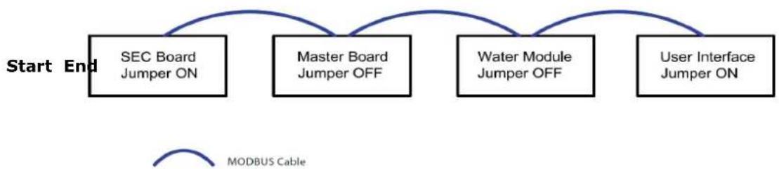
It is recommended to connect the Modbus cable in daisy-chain series (as shown in figure 11) from the heat pump on to the wiring centre and then on to the UI. The jumpers will be in the correct factory setting for this wiring configuration by default. If using the recommended configuration, the jumper position does not need to be changed.
If it is deemed necessary to install the Modbus cable in a different order, please see Appendix I
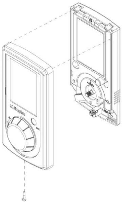
The cover of the UI must be removed in order to move the jumper. To remove the cover, unscrew the screw at the bottom of the UI and lift the cover and rotary dial.
To replace the cover, position the rotary dial over the holding pin on the board, ensuring the two are lined up correctly. Replace the cover and bottom screw.
Ensure that rotary dial is tested and working once cover has been replaced.
Figure 10: How to open the user interface
flowchart
graph LR
    A["Start End"] --> B["SEC Board Jumper ON"]
    A --> C["Master Board Jumper OFF"]
    A --> D["Water Module Jumper OFF"]
    A --> E["User Interface Jumper ON"]
    B --> F["MODBUS Cable"]
    C --> F
    D --> F
    E --> F
Figure 11: Recommended MODBUS cable configuration
4 Heat Pump Controller / Commissioning
4.1 Set To Work
When starting up the heat pump you must first ensure that;
• All covers are replaced.
• The heat pump isolator switch is switched on.
- The heat pump is connected to the mains power supply via a separate suitable circuit breaker and RCD protection.
• The wiring centre or DHW cylinder is connected to the mains power supply.
- The Modbus network is complete and the UI and the heat pump are connected to the wiring centre or DHW cylinder.
Once the connections have been made and the power supplies have been switched on, the system may take a couple of minutes to start up.
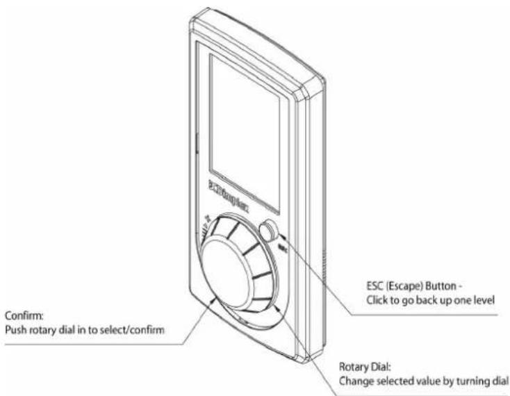
Figure 12: Using the User Interface
When switching on the heat pump for the first time, and after the start up sequence, you will be greeted by the home screen, shown in figure 13.
If the heat pump is already switched on but you wish to make changes to the settings, you may need to press Esc in order to go from the screensaver to the home screen.
To access the Installer Menu, you must select the information menu. Once you have entered the information menu, you must select 'Login', as shown in figure 14.
4.1.1 STARTING THE HEAT PUMP IN COLD WEATHER
When carrying out a commissioning and setting a heat pump to work in conditions where defrosting is required ( ≤12^ ) and/or the space heating return temperature is ≤18^ , start by heating the buffer tank. There is not currently a software function to close down the heating circuits, so to do this the rest of the heating circuit must be closed down manually to allow the buffer tank to heat up ( ≥25^ ).
Once this temperature has been achieved, individual heating circuits (i.e. zones) can be opened gradually. During this procedure, DO NOT:
- Allow excess volumes of cold water to return from the heating circuit
- Allow the heat pump return temperature to drop below 18°C
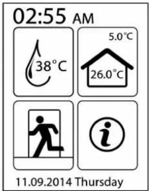
Figure 13: Home screen

DHW MENU ICON
Access to domestic hot water menu (shows current DHW temperature)

SPACE HEATING ICON
Access to space heating menu (shows current indoor and outside temperatures)

TEMPORARY MODES
Access to temporary modes menu

INFORMATION MENU
Access to information menu
4.1.2 BIVALENT MODE (ALTERNATIVE BACK-UP HEAT SOURCES)
If the heat pump cannot meet the heating load (if it is undersized for extreme conditions), the system must call on an alternative, back-up heat source. This bivalence feature is automatically triggered by the controller and allows a backup heater to help the heat pump in reaching its set point.
4.1.3 OPERATING MODES
There are three operating modes available; ON, OFF or TIMER. Please see the A Class User Manual for more information.

NOTE: YOU WILL NOT BE ABLE TO ACCESS ANY OTHER OPTIONS ON THE HOME SCREEN, EXCEPT THE INFORMATION MENU, UNTIL THE HEAT PUMP HAS BEEN FULLY COMMISSIONED.
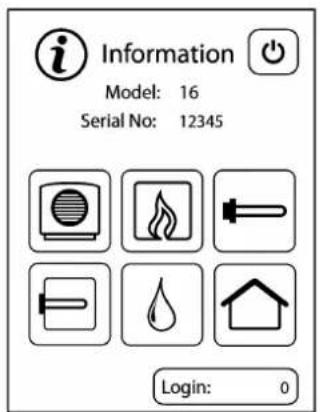
Figure 14: Information screen

Heat Pump Bivalent Boiler

Domestic Hot Water Space Heating

Backup Heater Hot Water Immersion


NOTE: THE MODEL NO. DISPLAYED ON THE INFORMATION SCREEN WILL BE 8, 12 OR 16 DEPENDING ON YOUR HEAT PUMP MODEL. THE SERIAL NUMBER DISPLAYED WILL BE SPECIFIC TO YOUR HEAT PUMP.

NOTE: ACCESS TO FUNCTIONS BY UNAUTHORIZED PERSONNEL NEGATES WARRANTY AND MAY CAUSE DAMAGE TO THE SYSTEM.
When using the Login function, input the installer access code (22 - Installer) by turning the dial to scroll through numbers, then pressing in the dial to select as before. You will then need to input 55 (commissioning menu code) to bring up the installer menu.
When you enter the installer menu, select the Language Selection option, which will bring you to the Start Guide screen. Selecting UK will bring you back to the Installer Menu, which will now display the Commissioning option.
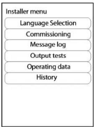
flowchart
graph TD
    A["Installer menu"] --> B["Language Selection"]
    B --> C["Commissioning"]
    C --> D["Message log"]
    D --> E["Output tests"]
    E --> F["Operating data"]
    F --> G["History"]
Figure 15: Installer menu once language selection is complete
4.2 Commissioning
Select 'Commissioning' to begin and follow the instructions on the system controller. The commissioning routine will take you through a number of checks and tests to complete the installation. When you finish using each submenu in the commissioning process, selecting 'Next' will take you back to the main Commissioning menu, where a new submenu will be available.
GENERAL / SCHEMATIC
In some cases, it may be necessary to carry out checks on individual components of the heating system before beginning the commissioning routine. Accessing General/Schematic menu allows you to set the date and time, and the level of access allowed. It is recommended that the Standard user access level is selected for most installations.
Selecting 'Next' will bring you to the Schematic menu, as shown in figure 17. Once you have selected a schematic zone diagram, a number of other options will become available in the main Installer menu. The schematic number refers to one of the plumbing schematics described in Appendix C. Please ensure that your plumbing reflects the diagram set up to ensure correct operation.
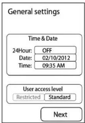
Figure 16: General menu
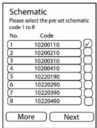
Figure 17: Schematic menu

NOTE: F ANY CHANGES MUST BE MADE TO THE COMMISSIONING CONFIGURATION (E.G. SELECTING A DIFFERENT PROBE), IT IS STRONGLY ADVISED THAT A FACTORY RESET IS PERFORMED AND THAT THE HEAT PUMP IS RECOMMISSIONED ENTIRELY. CHANGING INDIVIDUAL SETTINGS DURING THE COMMISSIONING PROCESS MAY CAUSE COMMANDS TO BE IGNORED OR CAUSE THE HEAT PUMP TO STOP WORKING CORRECTLY.
4.2.1 WATERSIDE CHECK
The 'Waterside Check' menu allows you to select whether temperature control is based on the flow or return temperature. This will apply to heating curves, as discussed in section 4.2.10.
It is generally always recommended to set the temperature control based on the return temperature, unless it is absolutely necessary to use flow temperature instead for a particular set up, as flow control may lead to unnecessary stopping and starting of the heat pump. Selecting 'Next' will bring you to the waterside checks menu (figure 18).
A number of waterside checks must be carried out as part of commissioning, and must be ticked as completed in the Waterside check menu:
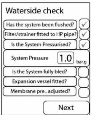
Figure 18: Waterside Check
• The system must be flushed.
- The strainer must be fitted to the return pipe and checked to ensure that it is clean.
• The system must be pressurized (You must enter the system pressure).
• The system must be fully bled.
• The expansion vessel must be fitted
- Membrane pressure of the expansion vessel must be checked and adjusted if required.
When checks are completed and 'Next' is selected, the type of temperature measurement devices to be used in each heating zone must also be selected by scrolling across and pressing confirm. The following options are available;
- User Interface (usually in zone 1 – heating system controller)
• Temperature probe (option for temperature probe 1 to 3, for additional zones).
• Mechanical thermostat (option for mechanical stat 1 to 3, for additional zones).
Using a mechanical stat limits the level of heating control on the zone from the UI. Heating in zones using temperature probes can be fully controlled using the UI. Selecting 'Next' will bring you to the 'Temperature check'

NOTE: SOME OF THE CHECKS ARE FUNCTIONAL AND WILL REQUIRE PHYSICALLY STARTING PUMPS, VALVES, ETC. RATHER THAN INPUTTING INFORMATION ON THE UI ONLY

NOTE: IF YOU LEAVE THE COMMISSIONING MENU BEFORE YOU SUCCESSFULLY COMPLETE COMMISSIONING, ALL PREVIOUS INFORMATION ENTERED WILL BE SAVED AND COMPLETED MENUS WILL BE HIGHLIGHTED IN GREEN. YOU CAN THEN RETURN TO IT AT A LATERSTAGE TO COMPLETE THE PROCESS.
4.2.2 TEMPERATURE CHECK
This screen displays the temperatures currently being read by all temperature probes. It is the duty of the installer to ensure that all sensors are installed and working correctly, and the boxes on this menu should not be ticked unless all displayed temperatures have been confirmed to be within an acceptable and expected range.
4.2.3 ELECTRICAL CONNECTIONS (SH)
This menu provides a list of electrical connections that should be made prior to commissioning for space heating. The list is based on the schematic zone diagram selected and also the type of temperature devices that will be used in each zone. Once you have confirmed all checks and select 'Next', you will return to the commissioning menu where you can now access the 'Water flow check' menu.
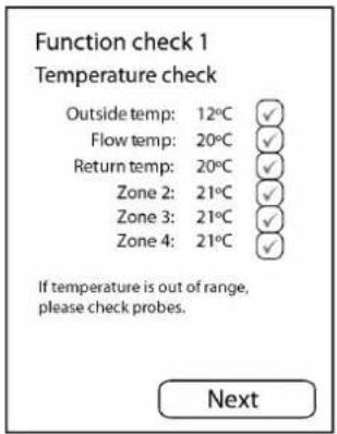
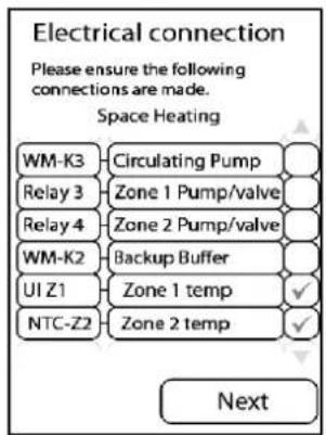
Figure 20: Electrical Connection Figure 19: Temperature Check
4.2.4 WATER FLOW CHECK
Select 'Run Test' to start the circulation pump. Ensure that all valves are open to allow flow. The circulation pump will be tested first by running for 30 seconds. When the timer reaches zero, the pump will continue to run until flow is confirmed, which allows time for the installer to check that the pump is working.
Once you are confident that the pump is on and that there is water flow, click 'Continue' to confirm that the pump is working correctly. Do not confirm that the pump is working in this menu unless you have physically checked it, as the UI requires your input and does not detect this automatically.
Once this is successful, the compressor will run for 5 minutes. As the test runs, the screen will give you information on the status of the heat pump and the time remaining on the test. If you do not have flow or if there is a problem, you can stop the test. If you stop the test, there is a 5 minute delay before you can attempt to run the test again. It is not possible to bypass the test, as good water flow is critical to the operation of the heat pump.
If there is no flow at all, a high pressure fault will appear on the UI screen and the commissioning will be aborted. Once the test is completed, you will see one of three messages:
- No flow detected
- Flow too low
- Flow detected
If you see message 1 or 2, this might be an indication of an air-lock, dirty strainer, flow restriction or pump too small for the required pipework. Please check for these issues and if present, rectify to ensure that there is sufficient flow then repeat the test. There will be a time delay before you can restart the test. When you see the screen shown in figure 21, with the pump highlighted in green, flow has been detected and the compressor 'flow check' test is complete. You will receive the status 'Waterside is OK' when the waterside checks are completed. Selecting 'Next' brings you to the Electrical Connections menu.
If carrying out start up in cold weather, commission the heat pump heating only the buffer. Once it reaches the required temperature open each zone slowly and in series, especially for under floor heating. If you have selected Schematic 1 or 3 (Space heating only or Bivalent space heating), move now to section 4.2.10 'Heating Curves' to complete the commissioning process.
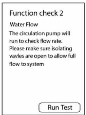
Figure 21: Water Flow Check
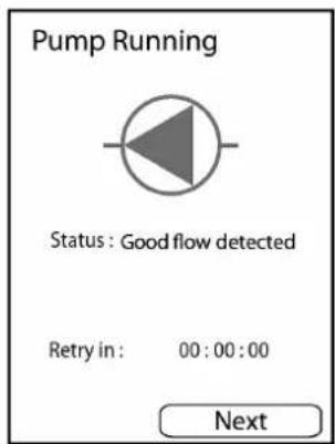
Figure 22: Successfully running test screen

NOTE: FOR SAFETY REASONS, IF THE HEAT PUMP PRESSURE EXCEEDS 38 BAR/TEMPERATURE EXCEEDS 60°C, THE COMMISSIONING WILL BE ABORTED. UNDER THESE CONDITIONS, MEASURES SHOULD BE TAKEN TO ALLOW THE TEMPERATURE TO DROP BELOW 60°C, I.E. A ZONE SHOULD BE OPENED.
4.2.5 DHW SETUP
Before commissioning the DHW, a number of checks must be carried out, as shown in figure 23. When you have ticked each box to confirm each DHW check, 'Next' will bring you back to the installer menu, where you can now select 'Electrical Connections (DHW)'.

NOTE: IT IS POSSIBLE TO USE SPACE HEATING WITHOUT COMPLETING THE DHW SETUP. THIS CAN BE DONE BY SELECTING 'N' ON THE DHW SETUP SCREEN WHERE IT ASKS IF THE CYLINDER IS CONNECTED (SEE FIGURE 23).
THIS MAY BE NECESSARY WHERE THE DHW IS NOT YET CONNECTED OR WHERE THE CYLINDER HAS NOT YET BEEN FILLED. WHEN THE CYLINDER IS READY, IT WILL BE NECESSARY TO RETURN TO THIS STEP OF THE COMMISSIONING AND SELECT 'Y' INSTEAD FOR "CYLINDER CONNECTED?" TO SET UP DOMESTIC HOT WATER.
4.2.6 ELECTRICAL CONNECTIONS (DHW)
This menu provides a list of electrical connections that should be made prior to commissioning the domestic hot water cylinder. You must check and confirm all connections in order to make the 'DHW Test' available in the installer menu. The numbers listed on the LHS of the screen refer to the following;
| On Screen | On Controller | On Connection Block | |
| S-DO-0Q2 | Relay 2 (to DHW-SH valve) | Connection 2 | on live block |
| S-DO-07 | Relay 7 (Immersion DHW) | Connection 4 or | live block |
| S-AI-01 | NTC-DHW (DHW temperature probe) | - |
Table 3: Electrical Connections screen information
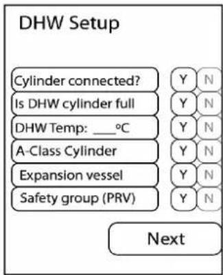
Figure 23: DHW Set-up menu
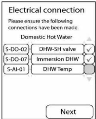
Figure 24: electrical connections
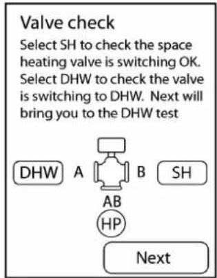
Figure 25: Valve Check screen
4.2.7 DHW TEST
Before you run the DHW test, which consists of heating up the cylinder to maximum temperature from the heat pump, you will be asked to check that the valve (figure 26) is in the DHW position (A position), as shown on the screen in figure 25. Check that the red actuator marker changes to the correct position (the default position is B).
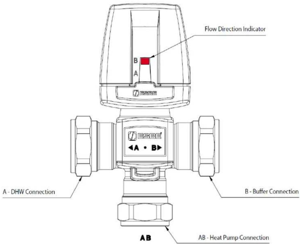
Figure 25: 3-Port Valve
When you have completed the valve check and select 'Next', you will see the DHW test screen, which informs that the test can take up to 90 minutes (based on a 300L cylinder). Selecting 'Run test' begins the DHW cycle and shows you the time remaining (see figure 27(a)).
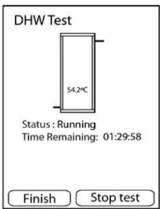
Figure 27(a): The test may be Postponed using the "Finish" button


NOTE: DURING THE DHW TEST, THE DEFROST FUNCTION WILL BE DISABLED. IF THE COIL STARTS FROSTING DUE TO EXTERNAL CONDITIONS, IT IS POSSIBLE TO POSTPONE THE DHW TEST BY SELECTING 'FINISH' ON THE DHW TEST SCREEN (SEE FIGURE 27(A)) WHILE THE TEST IS RUNNING. IF THE TEST IS POSTPONED, THE DHW CAN STILL BE USED.
NOTE: SELECTING 'STOP TEST' WILL CANCEL THE TEST COMPLETELY. IF THE DHW TEST HAS BEEN CANCELLED RATHER THAN POSTPONED, THE INFORMATION REGARDING THE IMMERSION DISPLAYED ON THE SET TEMPERATURE MENU FOR DHW WILL NOT BE CORRECT (THE IMMERSION WILL NOT BE USED UNTIL THE MAXIMUM TEMPERATURE ACHIEVABLE BY THE HEAT PUMP HAS BEEN REACHED).
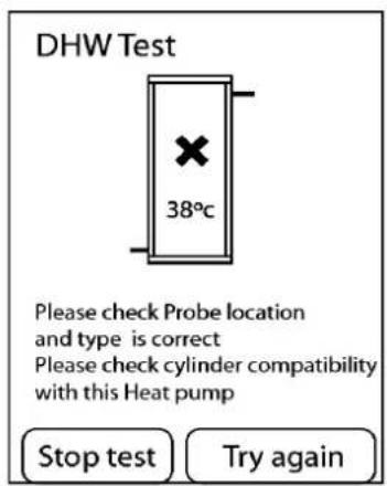
Figure 27(b): DHW Test Failed
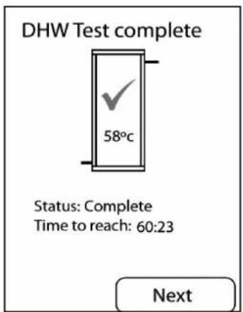
Figure 27(c): DHW Test completed
If the test fails, you will see the screen shown in figure 27(b), which provides information on why the test failed, and advice on checks to carry out.
If the test is complete and has been successful, you will see the screen shown in figure 27(c), which shows the maximum temperature that the cylinder can achieve.
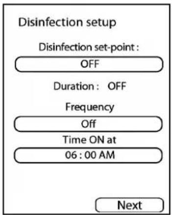
Figure 28: Disinfection Set-up
4.2.8 DISINFECTION (THERMAL)
Thermal disinfection is a function which keeps the level of legionella bacteria in the cylinder under acceptable levels. This is carried out by heating the hot water in the cylinder to a high temperature for a minimum set time.
The temperature and frequency of the disinfection cycle can be adjusted in this menu. If the temperature is set to above what the heat pump can achieve, text on the screen will appear which notifies that the immersion heater will be used at the end of the cycle to top up to the required disinfection temperature.
4.2.9 W EATHER COMPENSATION
The biggest factor in defining the heat demand required for a building is typically the weather. Which affects the required heat load for a building. Weather compensation works by adjusting the set point temperature of the heating system to reflect changes in the outside (external) temperature, allowing the heat pump to operate more efficiently.
Weather compensation is determined by the heat curve settings for the system. The pre-defined heating curves should only be modified by an installer to best match the heat emitters used.
4.2.10 HEATING CURVES
Each zone is associated to a pre-set heat curve. Selecting the zone and pressing 'Next' will allow you to assign a pre-set curve for typical heat emitters. The four pre-set heating curves are shown in table 4.
Each curve can be reviewed and modified to meet the requirements of the heating system by selecting 'Edit'. This will bring you to a default heating curve for the selected emitter. Selecting 'Next' will select the default heating curve.
The pre-defined curves have recommended temperature ranges for each heat emitter;
| Heat Emitter Type Max. Water Temp. at Low External Temp. | Min. Water Temp. at High External Temp. | |||
| SmartRad 48°C -10°C 35°C 10°C | ||||
| Underfloor Heating 30°C -10°C 25°C 12°C | ||||
| Standard Radiator 55°C 10°C 40°C 15°C | ||||
| Custom (Flat Line) 55°C -15°C 55°C 15°C | ||||
Table 4: Heating Curve Parameters
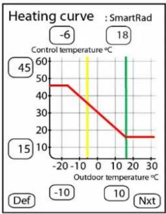
The values that generate the heating curve graph can be changed, by scrolling through the temperature value to adjust and setting it.
This is validated using the 'Set' button when complete (see figure 29).
line
| Outdoor temperature °C | Heating curve | | ---------------------- | ------------- | | -20 | 45 | | 18 | 18 | | 20 | 10 | | 30 | 15 |Figure 29: SmartRad Heating Curve
- The green line on the right indicates the maximum outdoor temperature at which space heating stops running (DHW is still adjusted independently).
- The yellow line on the left indicates the minimum outdoor temperature at which the bivalent heating system starts working and may need to be adjusted depending on the location/property.
- The red line indicates the temperature that the water will be heated to, based on the outdoor temperatures.
- The 'Default' option will reset the pre-defined values. Set will save entered values.

NOTE: IF THE HEAT PUMP IS IN HEATING "ON" MODE AND THE MAXIMUM OUTSIDE TEMPERATURE IS REACHED, THE HEAT PUMP WILL REVERT TO AND MAINTAIN THE SET BACK TEMPERATURE UNTIL THE HEATING IS TURNED OFF AND ON AGAIN. TO PREVENT THIS, IT IS RECOMMENDED TO SET YOUR SUMMER TEMPERATURE (SEE HEAT CURVES SECTION 4.2.10), AT A HIGHER VALUE (THE DEFAULT OUTSIDE AMBIENT SETTING IS 18°C).
COMFORT LEVEL
For end-users, the preferred method of modifying the heating system comfort level is by using the comfort level function rather than modifying the heat curve. Here, it is possible to raise or lower the water input temperature within a range of 9^ C (-3 to +6) by accessing the comfort level.
For more information please see the A-Class User Manual.

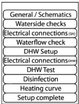
NOTE: TO COMPLETE COMMISSIONING AND ALLOW THE HEAT PUMP TO OPERATE, YOU MUST SELECT THE 'SETUP COMPLETE' SUBMENU IN THE INSTALLER MENU, AS SHOWN IN FIGURE(S) 30/31. IF YOU DO NOT SEE THIS SCREEN, COMMISSIONING HAS NOT BEEN SUCCESSFUL AND THE HEAT PUMP WILL NOT OPERATE CORRECTLY.
Once all of these steps have been carried out successfully, you will see the screen shown in figure 31. Selecting 'Automatic' will activate all settings, where as selecting 'Standby' will enable the heat pump only to carry out frost protection (i.e. no heating is required but the heat pump is protected from freezing conditions).
The default setting for the heat pump is OFF. To turn on the heat pump, you must return to the home screen to access the user menu.
For further information on end user controller instructions please see 'A-Class Air Source Heat Pump User Guide supplied in the Hydraulics Pack with this manual.
flowchart
graph TD
    A["General / Schematics"] --> B["Waterside checks"]
    B --> C["Electrical connections (SH)"]
    C --> D["Waterflow check"]
    D --> E["DHW Setup"]
    E --> F["Electrical connections (DHW)"]
    F --> G["DHW Test"]
    G --> H["Disinfection"]
    H --> I["Heating curve"]
    I --> J["Setup complete"]
Figure 30: Installer menu
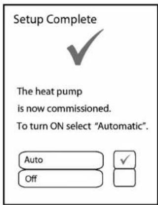
Figure 31: Commissioning complete
4.3 Additional Installer Menu Options
Once the commissioning process has been completed, additional menus will be available to the installer, as outlined in this section.
4.3.1 MESSAGE LOG
The message log menu provides a list of all errors that have taken place, including the date and time when they occurred. Selecting an individual error code will provide more information on the type of error that occurred if an SD card is present. Active error messages will show a ticked box.
Figure 31 shows an example of the messages shown in the 'message list' menu. When a new error occurs, it will appear at the top of the list. Up to 20 errors can be shown on the list at once, then, if another error occurs, the oldest error will be pushed off the list to make room for the new error. If the same error message is being displayed more than once, it may be necessary to check back through some of the older error messages in order to find the cause of the problem.

NOTE: IF A MAJOR FAULT OCCURS MANY TIMES, THE COMPRESSOR WILL GO INTO LOCK-OUT MODE TO PREVENT ANY FURTHER DAMAGE TO THE HEAT PUMP. IN ORDER TO RESOLVE THIS THE POWER TO THE COMPRESSOR WILL HAVE TO BE TURNED OFF FOR AT LEAST 2 MINUTES AND TURNED ON AGAIN.
4.3.2 OUTPUT TESTS
The output tests menu allows you to turn ON/OFF tests on individual components of the system, as shown in figure 33, and can be accessed once Electrical Connections (Space Heating) are confirmed.
The relays which control the immersion and backup heater/buffer use an electric interlocking system, and therefore R7 and R8 must be used together in order for the backup heater to function. Testing these relays individually will not reflect this.
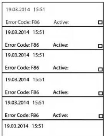
Figure 32: Message Log screen
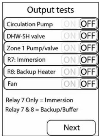
Figure 33: Output Tests screen
4.3.3 DEFROST
Before running a manual defrost cycle you must ensure the buffer has been isolated from the heating, as stated by the message on the UI. Selecting 'Start Defrost' begins the defrost cycle. The defrost screen will state the time remaining in the defrost cycle.
A heating water return temperature of ≥18^ is required for proper defrosting of the evaporator.

NOTE: THIS FUNCTION MUST ONLY BE USED WITH GREAT CARE BY TRAINED INSTALLERS, AS THE CONDENSER PLATE HEAT EXCHANGER MAY POTENTIALLY FREEZE IF THE WATER FLOW TEMPERATURE IS TOO LOW. THIS FUNCTION HAS THE POTENTIAL TO FREEZE THE CONDENSER (F43-47 ERROR MESSAGES ARE DEFROST ERRORS).
4.3.4 OPERATING DATA
The operating data menu provides a list of all the system parameters, such as all temperatures, including each zone set and actual temperatures, flow rate, and heat pump status. If an SD card is present, this data will be recorded to every message listed.
4.3.5 HISTORY
The History menu shows the temporary and permanent run time history of the system. These values can be reset in order to record run times over a certain time period. Selecting 'Next' brings you to the permanent run time history which cannot be reset unless a software update is installed.
4.3.6 SERVICE MENU
The service menu can be accessed, in a similar manner to the installation menu, by inputting the installer menu code (22) and then using the 'Login' access code 998. Access to this menu may be required for fault finding or servicing.
5 System Health Check/Maintenance
These are checks that should be carried out regularly to ensure that your Dimplex product performs at its best.
Heat pump:
□ Is the fan grille clear from debris? - Visual check
Is the tray clear from debris and water flowing freely? - Visual check
□ Is the condensate drain clear from debris?
Is the evaporator coil clean and free from damage? E.g. flattened fins
□ Are all of the outer panels secure?
Electrical:
□ Is the power cable firmly fixed?
Is the earth wire connection secure?
Is the supply voltage correct?
Hydraulics:
□ Is the system correctly pressurized?
Are there any water leaks in the system? Is the required pressure holding?
Is the strainer on the return pipe clear of debris? See section 3.2 for details on isolating and cleaning the strainer.

NOTE: IT IS RECOMMENDED THAT THE STRAINER IS CHECKED AND CLEANED 24 HOURS AFTER COMMISSIONING, AND EACH TIME THE SYSTEM IS MODIFIED OR HAS SERVICE WORK CARRIED OUT THEREAFTER.
Indoor settings:
Are the set temperatures and heating times suitable for the occupants?
Is the building warm enough for the occupants or does the heating curve need to be adjusted?
Appendices
• A - Technical Specifications
B - Refrigeration Cycle diagram
• C - Schematic Zone Diagrams - Legend
• D - Schematics 1, 2, 3 & 4 : Space Heating Only
E - Schematics 5, 6, 7 & 8 : Zone Space Heating & Domestic Hot Water
F - Schematics 9, 10, 11 & 12 : Bivalent Space Heating
G - Schematics 13, 14, 15 & 16 : Bivalent Zone Space Heating & Domestic Hot Water
• H - Wiring Centre Electrical Connections - with A-Class Cylinder
• I - Jumper Information for Alternative Wiring Configuration
• J - Controller Cable Connections
• K - Installer Menu Flow Chart
• Installer Hand-Over Form
• Certificate of Conformity
APPENDIX A: Technical Specifications – A Class Air-to-Water Heat Pump
| TECHNICAL SPECIFICATIONS | ||||||
| 1 | TYPE AND ORDER CODE | UNITS | A8M | A12M | A16M | |
| 2 DESIGN | ||||||
| 2.1 Degree of protection according to EN 029 for compact unit or heating element IP 24 | ||||||
| 2.2 Installation Location Outside | ||||||
| 3 PERFORMANCE DATA | ||||||
| 3.1 | Operating Temperature Limits | Min/Max | ||||
| Heating Water Typical Temperature Range | °C | 25/65 | ||||
| Outside Air Temperature Range | °C | -20/30 | ||||
| 3.2 | Heating Water Temperature Difference @ Standard Rating Condition | A7 W35 | K | 5 | ||
| Heat Output / COP | @ A7 W35 | kW/--- | 6.30 / 4.42 | 12.30 / 4.72 | 12.30 / 4.72 | |
| These figures characterise the size and performance of the system according to EN 14511 with clean heat exchangers. Abbreviations have he following meaning, e.g. A2 W35: Outside temperature 2°C and heating water supply temperature 35°C. A2 W35 test takes into account defrosting as per EN 14511. | @ A-2 W35 | kW/--- | 6.7 / 2.9 | 10.5 / 3.3 | 13.4 / 3.2 | |
| @ A-7 W35 | kW/--- | 7.0 / 2.9 | 12.0 / 3.0 | 13.2 / 3.0 | ||
| @ A7 W55 | kW/--- | 6.2 / 3.1 | 12.5 / 3.2 | 12.5 / 3.2 | ||
| @ A-2 W55 | kW/--- | 7.1 / 2.2 | 12.0 / 2.5 | 15.6 / 2.4 | ||
| @ A-7 W55 | kW/--- | 7.1 / 2.1 | 12.0 / 2.2 | 15.3 / 2.2 | ||
| @ A7 W65 | kW/--- | 6.3 / 2.7 | 12.4 / 2.6 | 12.4 / 2.6 | ||
| 3.3 Sound Power Level ^1 | dB(A) | 64 | 63.5 | 63.5 | ||
| 3.4 | Sound Pressure Level @ 10m (Heat Pump positioned against wall) | dB(A) | 41.5 | 38.5 | 38.5 | |
| 3.5 | Heating Water Flow Rate @ A7W35, nominal/minimum | m3/h | 1.15 / 0.85 | 2.1 / 1.2 | 2.1 / 1.2 | |
| 3.6 | Condenser Pressure Drop @ nominal flow rate (A7W35) | kPa | 3 | 4 | 4 | |
| 3.7 | Air Flow @ A7W35 | m3/h | 2600 | 3700 | 3700 | |
| 3.8 | Refrigerant; total filling weight | Type/kg | R410A / 1.75 | R410A / 2.0 | R410A / 2.0 | |
| 3.9 | Water Capacity of Stainless Steel Heat Exchanger | litre | 0.85 | 1 | 1 | |
| 3.10 | Polyol Ester Oil in Compressor | litre | 1.18 | |||
| 4 DIMENSIONS, CONNECTIONS & WEIGHT | ||||||
| 4.1 | Device Dimensions Without Connections | H x W x L (mm) | 1260 x 932 x 401 | 1571 X 932 X 401 | ||
| 4.2 Physical Volume | m3 | 0.5 | 0.59 | |||
| 4.3 Device Connections to Heating System | inch | 1" ext. thread | ||||
| 4.4 | Weight of the Transportable Unit (Excluding Packaging) | kg | 110 | 130 | ||
| 5 ELECTRICAL CONNECTIONS (HEAT PUMP) | ||||||
| 5.1 | Nominal Voltage; Fuse Protection | V/A | 230V / C32 | 230V / C 40 | ||
| 5.2 | Nominal Power Consumption / Nominal Current @ A7W35 | kW/A | 1.4 / 6.3 | 2.6 / 11 | ||
| 5.3 | Maximum Power Consumption / Maximum Current @ A-2W55 | kW/A | 4 / 19 | 6.9 / 30 | 8.1 / 35 | |
| 5.4 Maximum Starting Current - Inverter Ramp Up | Low (2.5A) | |||||
| 5.5 Power Factor A7W35 / (cos θ) | - | ≥0.94 | ≥0.95 | ≥0.95 | ||
| 5.6 | Electrical Supply Frequency | Hz | 50 | 50 | 50 | |
| 5.7 Power Input of Integral Fan @ A7W35 ^2 | W | 50 | 60 | 60 | ||
| 6 OTHER DESIGN CHARACTERISTICS | ||||||
| 6.1 Defrosting | Automatic | |||||
| 6.2 Type of Defrosting | Reverse Cycle | |||||
| 6.3 Heating Water in Device Protected Against Freezing by Software | Yes | |||||
^1 According to EN 12102.
^2 Fan is variable speed, rated input relates to nominal input power.
APPENDIX B - Refrigeration Cycle
REFRIGERANT CYCLE
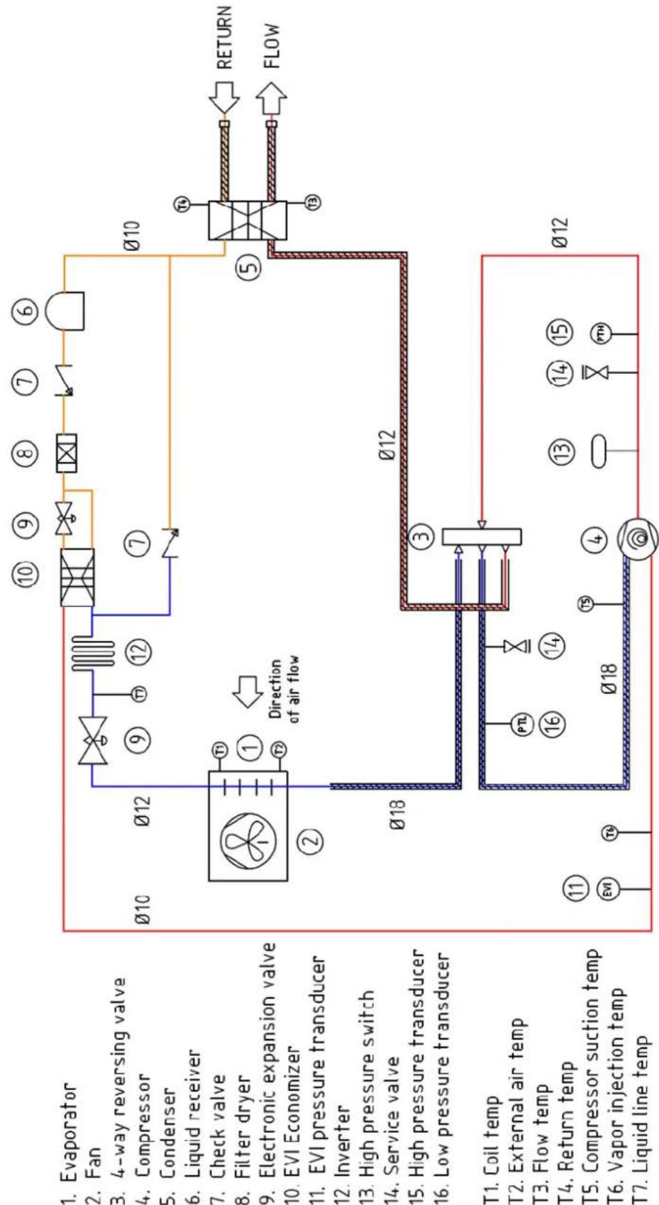
flowchart
graph TD
    A["Evaporator"] --> B["4-way reversing valve"]
    B --> C["Compressor"]
    C --> D["Condenser"]
    D --> E["Liquid receiver"]
    E --> F["Check valve"]
    F --> G["Filter dryer"]
    G --> H["Electronic expansion valve"]
    H --> I["EVI Economizer"]
    I --> J["EVI pressure transducer"]
    J --> K["Inverter"]
    K --> L["High pressure switch"]
    L --> M["Service valve"]
    M --> N["High pressure transducer"]
    N --> O["Low pressure transducer"]
    O --> P["T1 Coil temp"]
    P --> Q["External air temp"]
    Q --> R["T3 Flow temp"]
    R --> S["T4 Return temp"]
    S --> T["T5 Compressor suction temp"]
    T --> U["T6 Vapor injection temp"]
    U --> V["T7 Liquid line temp"]

    A --> W["Direction of air flow"]
    W --> X["012"]
    X --> Y["018"]
    Y --> Z["010"]

    subgraph Process Components
        AA["① EVI"] --> AB["②"]
        AC["③ PTL"] --> AD["④ 16"]
        AE["⑤ 13"] --> AF["⑥ 14"]
        AG["⑦ 12"] --> AH["⑧ 8"]
        AI["⑨ 9"] --> AJ["⑩ 10"]
        AK["⑪ 11"] --> AL["⑫ 13"]
        AM["⑬ 14"] --> AN["⑭ 15"]
        AO["⑮ 16"] --> AP["⑯ 17"]
        AQ["⑰ 18"] --> AR["⑱ 19"]
        AS["㉑ 10"] --> AT["㉒ 11"]
        AU["㉓ 12"] --> AV["㉔ 13"]
        AW["㉕ 14"] --> AX["㉖ 15"]
        AY["010"] --> AZ["012"]
        BA["012"] --> BB["018"]
APPENDIX C - Schematic Zone diagrams - Legend
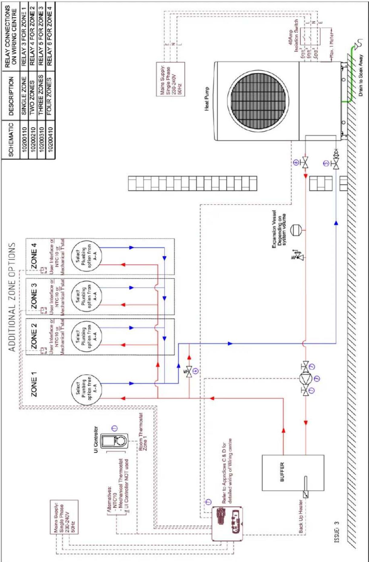
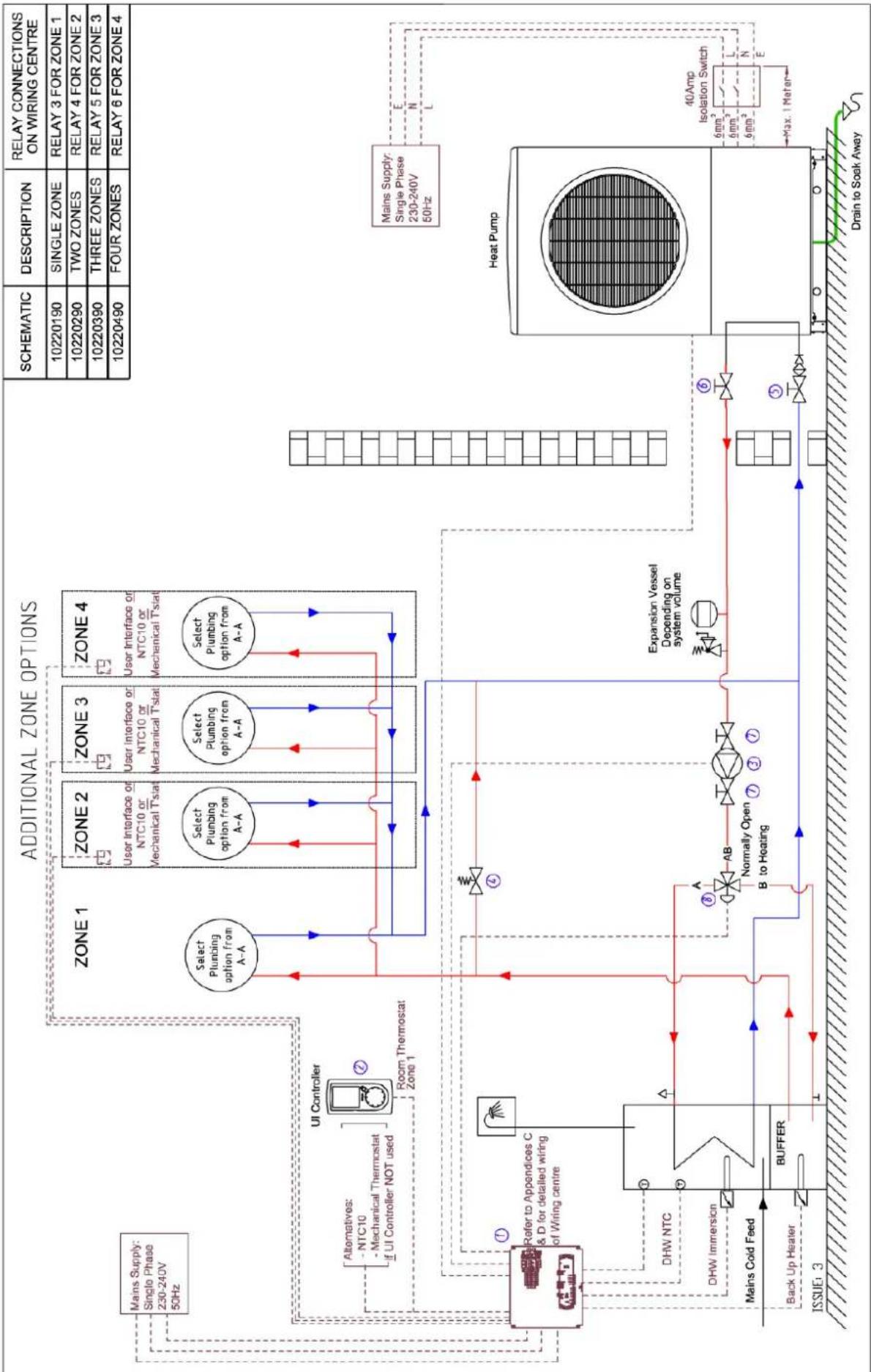
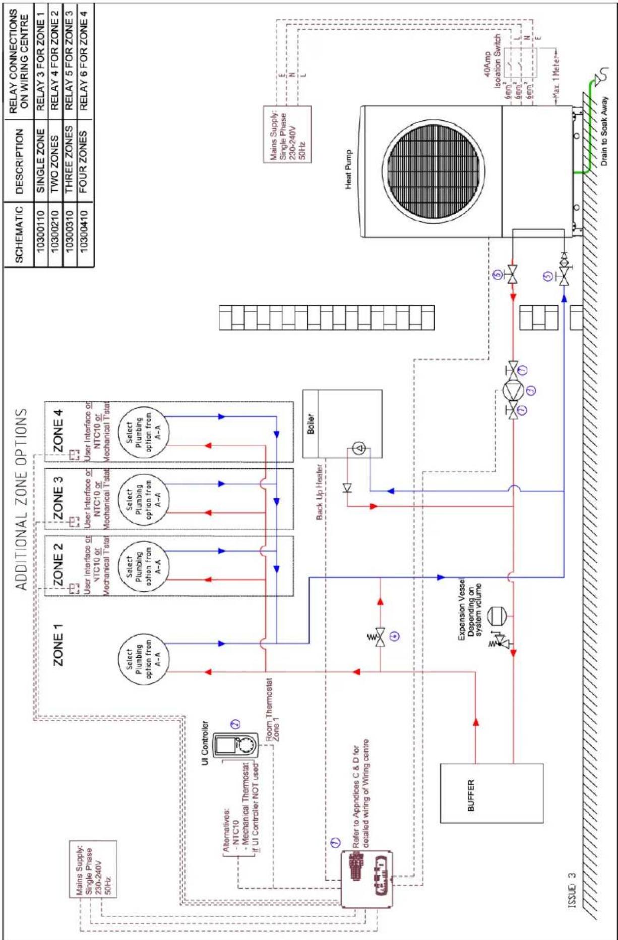
| No. on UI | Code | Heating type | No. of Zones | DHW | Appendix No. |
| 1 | 10200110 | Mono | 1 | No | D |
| 2 | 10200210 | Mono | 2 | No | D |
| 3 | 10200310 | Mono | 3 | No | D |
| 4 | 10200410 | Mono | 4 | No | D |
| 5 | 10220190 | Mono | 1 | Yes | E |
| 6 | 10220290 | Mono | 2 | Yes | E |
| 7 | 10220390 | Mono | 3 | Yes | E |
| 8 | 10220490 | Mono | 4 | Yes | E |
| 9 | 10300110 | Bivalent | 1 | No | F |
| 10 | 10300210 | Bivalent | 2 | No | F |
| 11 | 10300310 | Bivalent | 3 | No | F |
| 12 | 10300410 | Bivalent | 4 | No | F |
| 13 | 10310190 | Bivalent | 1 | Yes | G |
| 14 | 10310290 | Bivalent | 2 | Yes | G |
| 15 | 10310390 | Bivalent | 3 | Yes | G |
| 16 | 10310490 | Bivalent | 4 | Yes | G |
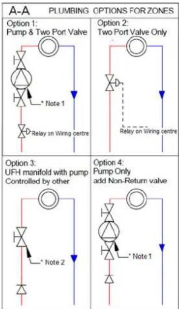
| KEY | HYDRAULIC SYMBOLS |
| Flow | |
| Return Flow | |
| Electrical Connections | |
| Isolating Valve | |
| Room Thermostat | |
| Pump | |
| Non-Return Valve | |
| Motorised 2 Port Valve | |
| Spring Loaded Bypass | |
| Motorised 3 Way Valve | |
| Safety Valve Combination | |
| Expansion Vessel | |
| Heat Load | |
| Immersion | |
| Drain | |
| Isolating Valve, Filter | |
| Air Vent | |
| Drain off valve |
Note 1: If EC pump is installed, it must be through a suitable external relay (high inrish current, not supplied). Note 2: Required for isolating the buffer during initial start-up
| ITEM | DESCRIPTION | PART NO. | KIT A(SH & DHW) | KIT B(SH ONLY) |
| 1 | WIRING CENTRE | 049186 | ||
| 2 | USER INTERFACE | 1754600 | 050489 | 049193 |
| 3 | PUMP - UPM GEO 25-85-180 | |||
| 4 | SPRING LOADED BYPASS | |||
| 5 | 28MM X 1" SWIVEL INTABALL COMBI | |||
| 6 | 28MM X 1" SWIVEL BALL VALVE | |||
| 7 | PUMP VALVE GATE 1"1/2X28mm | |||
| 8 | 3 PORT VALVE - VZD203 2-P |
APPENDIX D - Schematics 1, 2, 3 & 4 - Space Heating Only
flowchart
graph TD
    A["Main Supply: Single Phase 230-240V 50Hz"] --> B["UI Controller"]
    B --> C["Room Thermostat Zone 1"]
    C --> D["Zone 1"]
    D --> E["Select Plumbing option from A-A"]
    E --> F["Zone 2"]
    F --> G["User Interface or NTC10 or Mechanical Tstat"]
    G --> H["Zone 3"]
    H --> I["User Interface or NTC10 or Mechanical Tstat"]
    I --> J["Zone 4"]
    J --> K["User Interface or NTC10 or Mechanical Tstat"]
    K --> L["Zone 1"]
    L --> M["Zone 2"]
    M --> N["User Interface or NTC10 or Mechanical Tstat"]
    N --> O["Zone 3"]
    O --> P["User Interface or NTC10 or Mechanical Tstat"]
    P --> Q["Zone 4"]
    Q --> R["User Interface or NTC10 or Mechanical Tstat"]
    R --> S["Zone 1"]
    S --> T["Zone 2"]
    T --> U["User Interface or NTC10 or Mechanical Tstat"]
    U --> V["Zone 3"]
    V --> W["User Interface or NTC10 or Mechanical Tstat"]
    W --> X["Zone 4"]
    X --> Y["User Interface or NTC10 or Mechanical Tstat"]
    Y --> Z["Zone 1"]
    Z --> AA["Zone 2"]
    AA --> AB["User Interface or NTC10 or Mechanical Tstat"]
    AB --> AC["Zone 3"]
    AC --> AD["User Interface or NTC10 or Mechanical Tstat"]
    AD --> AE["Zone 4"]
    AE --> AF["User Interface or NTC10 or Mechanical Tstat"]
    AF --> AG["Zone 1"]
    AG --> AH["Zone 2"]
    AH --> AI["User Interface or NTC10 or Mechanical Tstat"]
    AI --> AJ["Zone 3"]
    AJ --> AK["User Interface or NTC10 or Mechanical Tstat"]
    AK --> AL["Zone 4"]
    AL --> AM["User Interface or NTC10 or Mechanical Tstat"]
    AM --> AN["Zone 1"]
    AN --> AO["Zone 2"]
    AO --> AP["User Interface or NTC10 or Mechanical Tstat"]
    AP --> AQ["Zone 3"]
    AQ --> AR["User Interface or NTC10 or Mechanical Tstat"]
    AR --> AS["Zone 4"]
    AS --> AT["User Interface or NTC10 or Mechanical Tstat"]
    AT --> AU["Zone 1"]
    AU --> AV["Zone 2"]
    AV --> AW["User Interface or NTC10 or Mechanical Tstat"]
    AW --> AX["Zone 3"]
    AX --> AY["User Interface or NTC10 or Mechanical Tstat"]
    AY --> AZ["Zone 4"]
    AZ --> BA["User Interface or NTC10 or Mechanical Tstat"]
APPENDIX E - Schematics 5, 6, 7 & 8 - Zone space heating & DHW
flowchart
graph TD
    A["Additional Zone Options"] --> B["Zone 1"]
    A --> C["Zone 2"]
    A --> D["Zone 3"]
    A --> E["Zone 4"]
    B --> F["Select Plumbing option from A-A"]
    C --> G["User Interface or NTC10 or Mechanical Tstat"]
    D --> H["User Interface or NTC10 or Mechanical Tstat"]
    E --> I["User Interface or NTC10 or Mechanical Tstat"]
    F --> J["Room Thermostat Zone 1"]
    G --> K["Room Thermostat Zone 1"]
    H --> L["Room Thermostat Zone 1"]
    I --> M["Room Thermostat Zone 1"]
    J --> N["Room Thermostat Zone 1"]
    K --> O["Room Thermostat Zone 1"]
    L --> P["Room Thermostat Zone 1"]
    M --> Q["Room Thermostat Zone 1"]
    N --> R["Room Thermostat Zone 1"]
    O --> S["Room Thermostat Zone 1"]
    P --> T["Room Thermostat Zone 1"]
    Q --> U["Room Thermostat Zone 1"]
    R --> V["Room Thermostat Zone 1"]
    S --> W["Room Thermostat Zone 1"]
    T --> X["Room Thermostat Zone 1"]
    U --> Y["Room Thermostat Zone 1"]
    V --> Z["Room Thermostat Zone 1"]
    W --> AA["Room Thermostat Zone 1"]
    X --> AB["Room Thermostat Zone 1"]
    Y --> AC["Room Thermostat Zone 1"]
    Z --> AD["Room Thermostat Zone 1"]
    AA --> AE["Room Thermostat Zone 1"]
    AB --> AF["Room Thermostat Zone 1"]
    AC --> AG["Room Thermostat Zone 1"]
    AD --> AH["Room Thermostat Zone 1"]
    AE --> AI["Room Thermostat Zone 1"]
    AF --> AJ["Room Thermostat Zone 1"]
    AG --> AK["Room Thermostat Zone 1"]
    AH --> AL["Room Thermostat Zone 1"]
    AI --> AM["Room Thermostat Zone 1"]
    AJ --> AN["Room Thermostat Zone 1"]
    AK --> AO["Room Thermostat Zone 1"]
    AL --> AP["Room Thermostat Zone 1"]
    AM --> AQ["Room Thermostat Zone 1"]
    AN --> AR["Room Thermostat Zone 1"]
    AO --> AS["Room Thermostat Zone 1"]
    AP --> AT["Room Thermostat Zone 1"]
    AQ --> AU["Room Thermostat Zone 1"]
    AR --> AV["Room Thermostat Zone 1"]
    AS --> AW["Room Thermostat Zone 1"]
    AT --> AX["Room Thermostat Zone 1"]
    AU --> AY["Room Thermostat Zone 1"]
    AV --> AZ["Room Thermostat Zone 1"]
APPENDIX F - Schematics 9, 10, 11 & 12 - Bivalent Space Heating
flowchart
graph TD
    A["Addition Zone Options"] --> B["Zone 1"]
    A --> C["Zone 2"]
    A --> D["Zone 3"]
    A --> E["Zone 4"]
    B --> F["Select Plumbing option from A-A"]
    C --> G["User Interface or NTC10 or Mechanical Tstat"]
    D --> H["User Interface or NTC10 or Mechanical Tstat"]
    E --> I["User Interface or NTC10 or Mechanical Tstat"]
    F --> J["Room Thermostat Zone 1"]
    G --> K["Back Up Heater"]
    H --> L["Boxer"]
    I --> M["Boxer"]
    J --> N["Buffer"]
    K --> O["Expansion Vessel Depending on System Volume"]
    L --> P["Heat Pump"]
    M --> Q["Heat Pump"]
    N --> R["Heat Pump"]
    O --> S["Heat Pump"]
    P --> T["Heat Pump"]
    Q --> U["Heat Pump"]
    R --> V["Heat Pump"]
    S --> W["Heat Pump"]
    T --> X["Heat Pump"]
    U --> Y["Heat Pump"]
    V --> Z["Heat Pump"]
    W --> AA["Heat Pump"]
    X --> AB["Heat Pump"]
    Y --> AC["Heat Pump"]
    Z --> AD["Heat Pump"]
    AA --> AE["Heat Pump"]
    AB --> AF["Heat Pump"]
    AC --> AG["Heat Pump"]
    AD --> AH["Heat Pump"]
    AE --> AI["Heat Pump"]
    AF --> AJ["Heat Pump"]
    AG --> AK["Heat Pump"]
    AH --> AL["Heat Pump"]
    AI --> AM["Heat Pump"]
    AJ --> AN["Heat Pump"]
    AK --> AO["Heat Pump"]
    AL --> AP["Heat Pump"]
    AM --> AQ["Heat Pump"]
    AN --> AR["Heat Pump"]
    AO --> AS["Heat Pump"]
    AP --> AT["Heat Pump"]
    AQ --> AU["Heat Pump"]
    AR --> AV["Heat Pump"]
APPENDIX G - Schematics 13, 14, 15 & 16 - Bivalent zone Space Heating & DHW
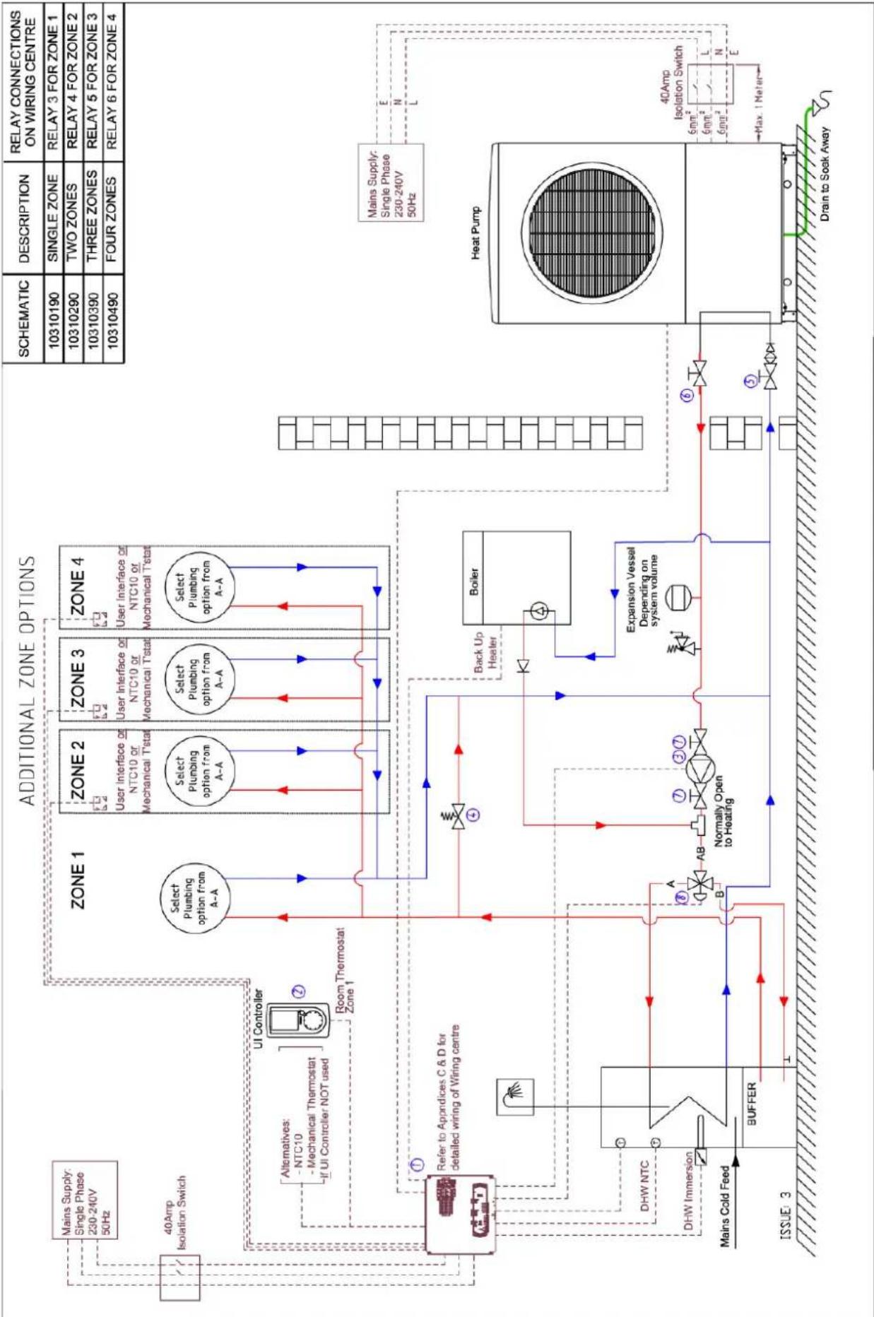
flowchart
graph TD
    A["Addition Zone Options"] --> B["Zone 1"]
    A --> C["Zone 2"]
    A --> D["Zone 3"]
    A --> E["Zone 4"]
    B --> F["Select Plumbing option from A-A"]
    C --> G["User Interface or NTC10 or Mechanical Tstat"]
    D --> H["User Interface or NTC10 or Mechanical Tstat"]
    E --> I["User Interface or NTC10 or Mechanical Tstat"]
    F --> J["Room Thermostat Zone 1"]
    G --> K["User Interface or NTC10 or Mechanical Tstat"]
    H --> L["User Interface or NTC10 or Mechanical Tstat"]
    I --> M["User Interface or NTC10 or Mechanical Tstat"]
    J --> N["UI Controller"]
    K --> O["UI Controller"]
    L --> P["UI Controller"]
    M --> Q["UI Controller"]
    N --> R["UI Controller"]
    O --> S["UI Controller"]
    P --> T["UI Controller"]
    Q --> U["UI Controller"]
    R --> V["UI Controller"]
    S --> W["UI Controller"]
    T --> X["UI Controller"]
    U --> Y["UI Controller"]
    V --> Z["UI Controller"]
    W --> AA["UI Controller"]
    X --> AB["UI Controller"]
    Y --> AC["UI Controller"]
    Z --> AD["UI Controller"]
    AA --> AE["UI Controller"]
    AB --> AF["UI Controller"]
    AC --> AG["UI Controller"]
    AD --> AH["UI Controller"]
    AE --> AI["UI Controller"]
    AF --> AJ["UI Controller"]
    AG --> AK["UI Controller"]
    AH --> AL["UI Controller"]
    AI --> AM["UI Controller"]
    AJ --> AN["UI Controller"]
    AK --> AO["UI Controller"]
    AL --> AP["UI Controller"]
    AM --> AQ["UI Controller"]
    AN --> AR["UI Controller"]
    AO --> AS["UI Controller"]
    AP --> AT["UI Controller"]
    AQ --> AU["UI Controller"]
    AR --> AV["UI Controller"]
    AS --> AW["UI Controller"]
    AT --> AX["UI Controller"]
    AU --> AY["UI Controller"]
    AV --> AZ["UI Controller"]
    AW --> BA["UI Controller"]
    AX --> BB["UI Controller"]
    AY --> BC["UI Controller"]
    AZ --> BD["UI Controller"]
    BA --> BE["UI Controller"]
    BB --> BF["UI Controller"]
    BC --> BG["UI Controller"]
    BD --> BH["UI Controller"]
    BE --> BI["UI Controller"]
    BF --> BJ["UI Controller"]
APPENDIX H - Wiring centre electrical connections – with A Class cylinder
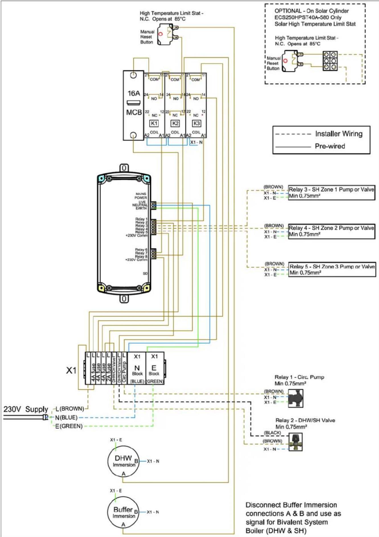
flowchart
graph TD
    A["High Temperature Limit Stat - N.C. Opens at 85°C"] --> B["16A MCB"]
    B --> C["COM1"]
    B --> D["NO"]
    B --> E["NC"]
    B --> F["K1"]
    B --> G["K2"]
    B --> H["K3"]
    B --> I["A2"]
    B --> J["A1"]
    B --> K["A2"]
    B --> L["A1"]
    B --> M["X1-N"]
    N["OPTIONAL - On Solar Cylinder ECS250HPST40A-580 Only Solar High Temperature Limit Stat"] --> O["High Temperature Limit Stat - N.C. Opens at 85°C"]
    P["Manual Reset Button"] --> Q["Coil A1"]
    P --> R["Coil A2"]
    P --> S["Coil A1"]
    T["BROWN"] --> U["X1-N"]
    T --> V["X1-E"]
    W["Relay 3 - SH Zone 1 Pump or Valve Min 0.75mm²"] --> X["BROWN"]
    Y["Relay 4 - SH Zone 2 Pump or Valve Min 0.75mm²"] --> Z["BROWN"]
    AA["Relay 5 - SH Zone 3 Pump or Valve Min 0.75mm²"] --> AB["BROWN"]
    AC["Relay 1 - Circ. Pump Min 0.75mm²"] --> AD["BROWN"]
    AE["Relay 2 - DHW/SH Valve Min 0.75mm²"] --> AF["BRACK"]
    AG["Buffer Immersion"] --> AH["X1-N"]
    AI["230V Supply"] --> AJ["L(BROWN)"]
    AK["N(BLUE)"] --> AL["E(GREEN)"]
    AM["DHW Immersion"] --> AN["X1-N"]
    AO["Buffer Immersion"] --> AP["X1-N"]
APPENDIX I - Jumper Information for Alternative Wiring Configuration

flowchart
graph LR
    A["SEC Board Jumper ON"] --> B["Master Board Jumper OFF"]
    B --> C["User Interface Jumper OFF"]
    C --> D["Water Module Jumper ON"]
    style A fill:#f9f,stroke:#333
    style B fill:#f9f,stroke:#333
    style C fill:#f9f,stroke:#333
    style D fill:#f9f,stroke:#333

MODBUS Cable
Alternative Modbus network configuration
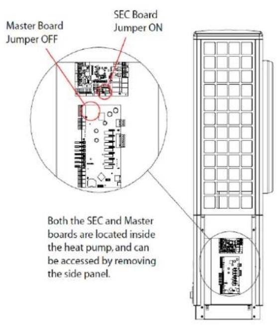
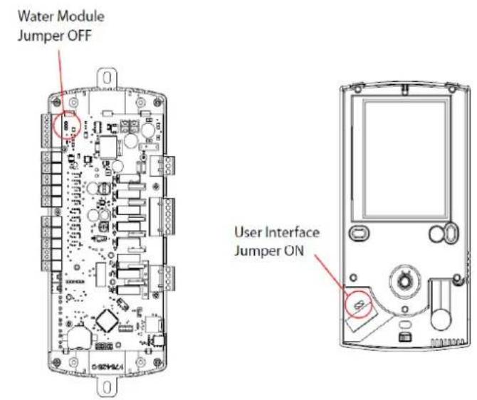
The water module can be located inside the A-Class cylinder, or in the wiring centre for installations not using an A-Class cylinder
Locations of jumpers that should be in the ON/OFF position for the recommended configuration
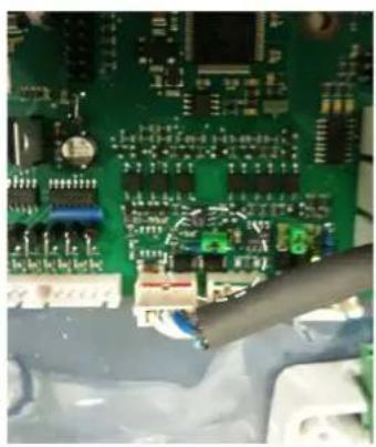
natural_image
Close-up of a green printed circuit board with electronic components and connectors (no visible text or symbols)Jumper in ON position on SEC board
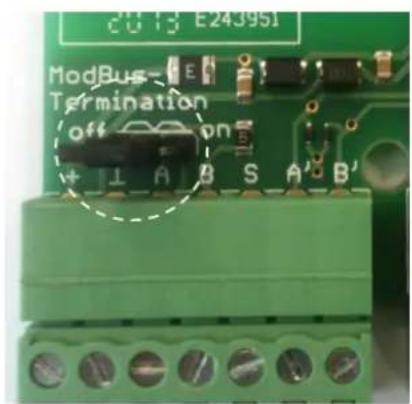
Jumper in the OFF position on water module
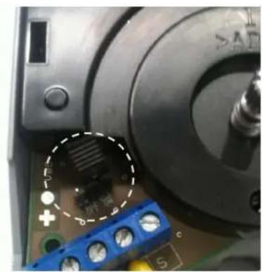
natural_image
Close-up of a mechanical component with a highlighted circular feature and blue terminal blocks (no readable text or symbols)Jumper in the ON position on user interface (UI)
APPENDIX J - Controller cable connections
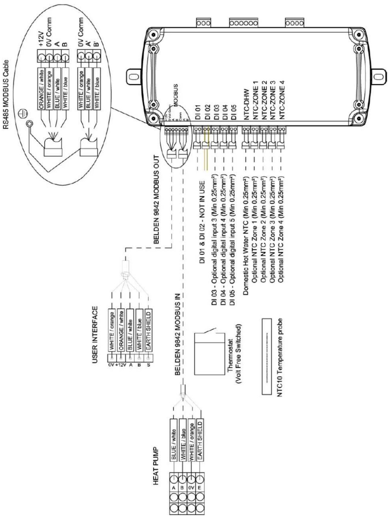
flowchart
graph TD
    A["HEAT PUMP"] --> B["BELDEN 9842 MODBUS IN"]
    B --> C["USER INTERFACE"]
    C --> D["RS485 MODBUS Cable"]
    D --> E["DI 01 & DI 02 - NOT IN USE"]
    E --> F["NI 10 Temperature probe"]
    E --> G["NI 02 - DI 03"]
    E --> H["NI 03 - DI 04"]
    E --> I["NI 05 - DI 05"]
    E --> J["NI 03 - DI 04 - DI 05"]
    E --> K["NI 03 - DI 05 - DI 05"]
    E --> L["NI 03 - DI 05 - DI 05"]
    E --> M["NI 03 - DI 05 - DI 05"]
    E --> N["NI 03 - DI 05 - DI 05"]
    E --> O["NI 03 - DI 05 - DI 05"]
    E --> P["NI 03 - DI 05 - DI 05"]
    E --> Q["NI 03 - DI 05 - DI 05"]
    E --> R["NI 03 - DI 05 - DI 05"]
    E --> S["NI 03 - DI 05 - DI 05"]
    E --> T["NI 03 - DI 05 - DI 05"]
    E --> U["NI 03 - DI 05 - DI 05"]
    E --> V["NI 03 - DI 05 - DI 05"]
    E --> W["NI 03 - DI 05 - DI 05"]
    E --> X["NI 03 - DI 05 - DI 05"]
    E --> Y["NI 03 - DI 05 - DI 05"]
    E --> Z["NI 03 - DI 05 - DI 05"]
    E --> AA["NI 03 - DI 05 - DI 05"]
    E --> AB["NI 03 - DI 05 - DI 05"]
    E --> AC["NI 03 - DI 05 - DI 05"]
    E --> AD["NI 03 - DI 05 - DI 05"]
    E --> AE["NI 03 - DI 05 - DI 05"]
    E --> AF["NI 03 - DI 05 - DI 05"]
    E --> AG["NI 03 - DI 05 - DI 05"]
    E --> AH["NI 03 - DI 05 - DI 05"]
    E --> AI["NI 03 - DI 05 - DI 05"]
    E --> AJ["NI 03 - DI 05 - DI 05"]
    E --> AK["NI 03 - DI 05 - DI 05"]
    E --> AL["NI 03 - DI 05 - DI 05"]
    E --> AM["NI 03 - DI 05 - DI 05"]
    E --> AN["NI 03 - DI 05 - DI 05"]
    E --> AO["NI 03 - DI 05 - DI 05"]
    E --> AP["NI 03 - DI 05 - DI 05"]
    E --> AQ["NI 03 - DI 05 - DI 05"]
    E --> AR["NI 03 - DI 05 - DI 05"]
    E --> AS["NI 03 - DI 05 - DI 05"]
    E --> AT["NI 03 - DI 05 - DI 05"]
    E --> AU["NI 03 - DI 05 - DI 05"]
    E --> AV["NI 03 - DI 05 - DI 05"]
    E --> AW["NI 03 - DI 05 - DI 05"]
    E --> AX["NI 03 - DI 05 - DI 05"]
    E --> AY["NI 03 - DI 05 - DI 05"]
    E --> AZ["NI 03 - DI 05 - DI 05"]
    E --> BA["NI 03 - DI 05 - DI 05"]
    E --> BB["NI 03 - DI 05 - DI 05"]
    E --> BC["NI 03 - DI 05 - DI 05"]
    E --> BD["NI 03 - DI 05 - DI 05"]
    E --> BE["NI 03 - DI 05 - DI 05"]
    E --> BF["NI 03 - DI 05 - DI 05"]
    E --> BG["NI 03 - DI 05 - DI 05"]
    E --> BH["NI 03 - DI 05 - DI 05"]
    E --> BI["NI 03 - DI 05 - DI 05"]
    E --> BJ["NI 03 - DI 05 - DI 05"]
    E --> BK["NI 03 - DI 05 - DI 05"]
    E --> BL["NI 03 - DI 05 - DI 05"]
    E --> BM["NI 03 - DI 05 - DI 05"]
    E --> BN["NI 03 - DI 05 - DI 05"]
    E --> BO["NI 03 - DI 05 - DI 05"]
    E --> BP["NI 03 - DI 05 - DI 05"]
    E --> BQ["NI 12V +12V White Comm A B"]
APPENDIX K - Installer Menu Flow Chart
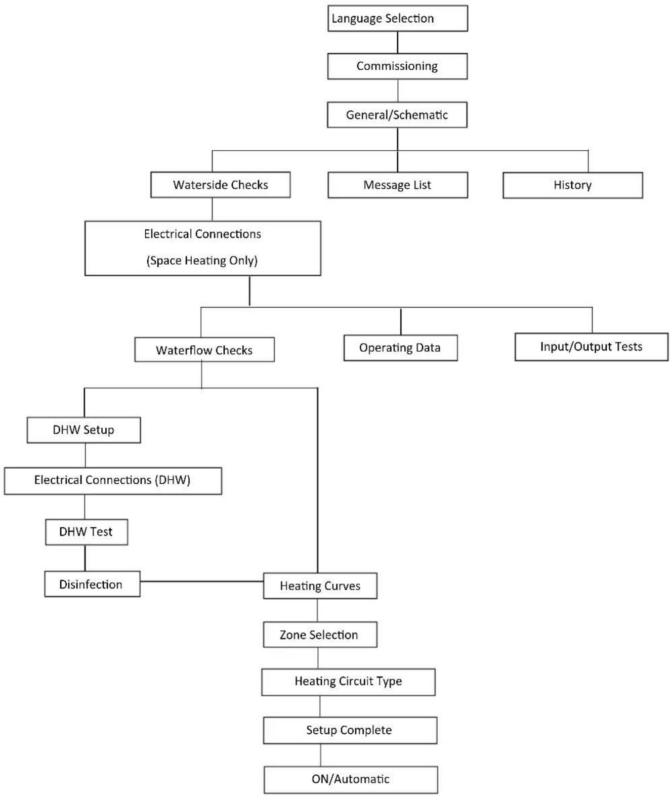
flowchart
graph TD
    A["Language Selection"] --> B["Commissioning"]
    B --> C["General/Schematic"]
    C --> D["Waterside Checks"]
    C --> E["Message List"]
    C --> F["History"]
    D --> G["Electrical Connections (Space Heating Only)"]
    G --> H["Waterflow Checks"]
    G --> I["Operating Data"]
    G --> J["Input/Output Tests"]
    H --> K["DHW Setup"]
    K --> L["Electrical Connections (DHW)"]
    L --> M["DHW Test"]
    M --> N["Disinfection"]
    N --> O["Heating Curves"]
    O --> P["Zone Selection"]
    P --> Q["Heating Circuit Type"]
    Q --> R["Setup Complete"]
    R --> S["ON/Automatic"]
Installer menu flow chart
Each submenu will appear once the upper level menu has been completed. Availability of menus will depend on the schematic zone diagram selected (as shown in Appendix B).
Installer Hand-Over Form
| Installer Name & Address: | |||
| Installer Contact Phone Number; | Installer Contact Email | Address: | |
| MCS Installer Number: | |||
| Date of Installation / Commissioning: | |||
| Heat Pump Model: HP Serial | Number (from | nameplate): | |
| Cylinder Model / Serial Number: | |||
| Accessories Installed: | |||
| Schematic number used for commissioning: | |||
| Details of Zone Control and Heat Emitters Installed: | |||
| Any other relevant information: | |||
Note: this installation manual needs to be left with the end user.
CE
EC Declaration of Conformity
GDC Group Limited, Millbrook House, Grange Drive, Hedge End, Southampton, Hants, SO302DF, United Kingdom
Manufacturer:
GDC Group, Greenbank Industrial Estate, Rampart Road, Newry, Co. Down, BT34 2QU
Hereby certified that the following device(s) complies/comply with the applicable EU directives. This certification loses its validity if the device(s) is/are modified.
Description: Heat Pump
Type: Air-to-Water
Model: A16M
Model: A12M
Model: A8M
EC Directives:
Low voltage directive 2006/95/EC
EMC directive 2004/108/EC
Pressure equipment directive 97/23/EC
Applied Standards:
EN 60335-1:2002+A11+A1+A12+corr.+A2:2006; EN60335-1/A13:2008; EN60335-2-
40:2003+A11+A12+A1+corr.+A2:2009
EN55014-1:2006; EN55014-2:1997+A1:2001
EN61000-3-2:2006; EN61000-3-3:1995+A1:2001+A2:2005
EN378-1:2008; EN378-2:2008+A1:2009; EN378-3:2008; EN378-4:2008
EN 14511-1:2007; EN14511-2:2007; EN14511-3:2007+EN14511-3:2007/AC:2008;
EN14511-4:2007
Conformity assessment procedure according to pressure equipment directive:
Module A
CE mark added:
2013
EC declaration of conformity issued on:
25 ^th September 2014
Ireland, 25.09.14
Technical Director
Martin Betz:
Issue: 1.03
- DCDimplexrenewables®
- A Class Air Source Heat Pump
- A8M / A12M / A16M Installation Manual
- Table of Contents
- Overview - Air to Water Heat Pump 1
- Introduction 5
- Preparation 9
- Installation 12
- Heat Pump Controller / Commissioning 21
- Commissioning 23
- Introduction
- Scope of Delivery
- Safety Warnings
- H ANDLING AND TRANSPORT
- GENERAL
- SAFETY
- MAINTENANCE
- E
- LECTRICAL WARNINGS
- INTENDED USE
- LEGAL
- H EAT PUMP SIZING
- Preparation
- Site Selection
- LOCATION OF HEAT PUMP
- LOCATION OF INDOOR COMPONENTS
- LOCATION OF WIRING CENTRE
- H EAT PUMP PLACEMENT AND FIXING
- Installation
- Plumbing Information
- P IPE SIZING INFORMATION
- BUFFER TANK
- Buffer Tank Sizing
- M ETERING FOR THE DOMESTIC RENEWABLE HEAT INCENTIVE - UK
- Plumbing - Installation
- Adjusting the By-Pass Valve
- Electrical Information
- Warnings
- A CCESS TO ELECTRICAL CONNECTIONS - OPENING THE HEAT PUMP
- ELECTRICAL CONNECTIONS - POWER AND COMMUNICATION CABLEHEAT PUMP CONNECTIONS
- MODBUS CABLE INFORMATION
- OPENING AND INSTALLING THE USER INTERFACE
- Heat Pump Controller / Commissioning
- Set To Work
- STARTING THE HEAT PUMP IN COLD WEATHER
- BIVALENT MODE (ALTERNATIVE BACK-UP HEAT SOURCES)
- OPERATING MODES
- Commissioning
- GENERAL / SCHEMATIC
- WATERSIDE CHECK
- TEMPERATURE CHECK
- ELECTRICAL CONNECTIONS (SH)
- WATER FLOW CHECK
- DHW SETUP
- ELECTRICAL CONNECTIONS (DHW)
- DHW TEST
- DISINFECTION (THERMAL)
- W EATHER COMPENSATION
- HEATING CURVES
- COMFORT LEVEL
- Additional Installer Menu Options
- MESSAGE LOG
- OUTPUT TESTS
- DEFROST
- OPERATING DATA
- HISTORY
- SERVICE MENU
- System Health Check/Maintenance
- Heat pump:
- Electrical:
- Hydraulics:
- Indoor settings:
- Appendices
- Installer menu flow chart
- CE
- EC Declaration of Conformity
- Manufacturer:
- EC Directives:
- Applied Standards:
Brand : DIMPLEX
Model : A8M
Category : Heat pump