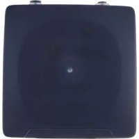
EIO404 - Bluetooth base station IFM - Free user manual and instructions
Find the device manual for free EIO404 IFM in PDF.


User questions about EIO404 IFM
0 question about this device. Answer the ones you know or ask your own.
Ask a new question about this device
Download the instructions for your Bluetooth base station in PDF format for free! Find your manual EIO404 - IFM and take your electronic device back in hand. On this page are published all the documents necessary for the use of your device. EIO404 by IFM.
USER MANUAL EIO404 IFM
Operating instructions
Bluetooth® Mesh IoT base station
EIO404
Firmware: 1.55
Contents
1 Preliminary note 5
1.1 Legal and copyright information 5
1.2 Symbols used 5
1.3 Warnings.... 5
2 Safety instructions.... 6
2.1 Cybersecurity 6
2.2 Safety symbol on the device 7
3 Intended use 8
3.1 Foreseeable misuse 8
3.2 Topology of the Bluetooth Mesh network 8
4 Function 10
4.1 Visual indication 10
4.2 Ethernet interface 10
4.3 Bluetooth LE 10
4.4 Bluetooth Mesh.... 10
4.5 ifm IoT-Core 10
5 Installation.... 11
5.1 Overview.... 11
5.2 Mounting options.... 11
5.2.1 Mounting without accessories 11
5.2.2 Installation with E80335 angle bracket 11
5.2.3 Installation with E80336 mounting device 12
5.2.4 Installation with E80337 fixing bars 12
5.3 Mounting the device 12
6 Electrical connection.... 13
6.1 Overview.... 13
6.2 General notes on wiring 13
6.3 Voltage supply 13
6.4 Ethernet port 14
7 Operating and display elements 15
7.1 Overview.... 15
7.2 Status LED 15
8 Parameter setting 16
8.1 Notes on parameter setting.... 16
8.1.1 Parameter setting via Bluetooth interface 16
8.1.2 Parameter setting via Ethernet interface 16
8.1.3 Installing ifm moneo|blue.... 17
8.1.4 Installing ifm moneo|configure.... 17
8.1.5 Bluetooth password.... 17
8.2 ifm moneo|blue 19
8.2.1 Connecting to the device.... 19
8.2.1.1 Provisioning Bluetooth Mesh IO-Link adapters 19
8.2.1.2 Removing a Bluetooth Mesh IO-Link adapter from the network..... 20
8.2.2 Reading identification information 21
8.2.3 Configuring IP settings 21
8.2.4 Setting the Bluetooth Mesh network name 21
8.2.5 Setting the Bluetooth station name 21
8.2.6 Configuring the MQTT connection.... 21
8.2.7 Configuring the MQTT command channel.... 22
8.2.8 Firmware update.... 22
8.2.8.1 Updating the firmware of the connected adapters 23
8.3 ifm IoT Core REST API 24
8.3.1 ifm IoT Core: General information 24
8.3.1.1 Accessing the ifm IoT Core 24
8.3.2 Getting started 26
8.3.3 General functions 27
8.3.3.1 Example: Change a parameter value 27
8.3.3.2 Example: Read multiple parameter values simultaneously ..... 28
8.3.3.3 Example: Output a subtree 28
8.3.3.4 Example: Search the IoT Core 29
8.3.4 Ethernet: Configuring IP settings.... 30
8.3.5 Ethernet: Configuring password protection 30
8.3.5.1 Example: Set an Ethernet password 31
8.3.5.2 Example: Request with authentication 31
8.3.5.3 Example: Delete an Ethernet password 32
8.3.6 Bluetooth: Setting a station name 33
8.3.7 Bluetooth: Configuring password protection 33
8.3.7.1 Example: Change a Bluetooth password.... 33
8.3.8 Managing the Bluetooth mesh network 34
8.3.8.1 Example: Scan for available mesh adapters 34
8.3.8.2 Example: Register mesh adapter with mesh network 35
8.3.8.3 Example: Replace mesh adapter 35
8.3.8.4 Example: Deregister mesh adapter from mesh network 36
8.3.9 Managing the Bluetooth mesh IO-Link adapters 36
8.3.10 Configuring the timers.... 37
8.3.10.1 Example: Set the counting interval 37
8.3.10.2 Example: Start the counter 37
8.3.10.3 Example: Stop the counter 38
8.3.11 Using notifications.... 38
8.3.11.1 Event-triggered notifications 39
8.3.11.2 Time-triggered notifications.... 39
8.3.11.3 Example: Create a time-triggered notification 39
8.3.11.4 Example: Create an event-triggered notification 40
8.3.11.5 Example: Show active notifications 41
8.3.11.6 Example: Change a notification.... 41
8.3.11.7 Example: Delete a notification.... 42
8.3.12 Using MQTT 42
8.3.12.1 Configuring the MQTT connection.... 43
8.3.12.2 Configuring the MQTT command channel.... 44
8.3.12.3 Example: Configure and activate the MQTT command channel ..... 44
8.3.12.4 Example: Publish the device temperature to an MQTT broker ..... 46
8.3.13 Resetting, rebooting and localising the device.... 47
8.3.14 Reading and writing device information.... 47
8.3.15 Reading status and diagnostic information 48
8.4 ifm moneo|configure 49
8.4.1 Connecting to the device.... 49
8.4.1.1 Provisioning Bluetooth Mesh IO-Link adapters 49
8.4.1.2 Removing a Bluetooth Mesh IO-Link adapter from the mesh network.....50
8.4.2 Info: Reading identification information 51
8.4.3 IoT: Configuring IP settings.... 51
8.4.4 IoT: Configuring password protection 52
8.4.4.1 Setting an Ethernet password 52
8.4.4.2 Resetting an Ethernet password 52
8.4.5 Bluetooth LE: Setting station names 53
8.4.6 Bluetooth LE: Configuring password protection.... 53
8.4.6.1 Change a Bluetooth password 53
8.4.7 Bluetooth Mesh: Managing the network 54
8.4.8 MQTT: Configuring the MQTT connection.... 54
8.4.8.1 Controlling the MQTT connection 54
8.4.9 MQTT: Configuring the command channel 55
8.4.9.1 Controlling the MQTT command channel 56
8.4.10 Timer: Configuring the timers 56
8.4.10.1 Starting the timer.... 56
8.4.10.2 Stopping the timer....57
8.4.11 Firmware: Resetting, rebooting or localising the device.... 57
8.5 IoT-Core Visualizer 58
8.5.1 Starting the IoT Core Visualizer.... 58
8.5.2 Managing notifications 58
8.5.2.1 Create new notifications 58
8.5.2.2 Delete notifications 59
8.5.3 Accessing the IoT Core tree 60
8.5.3.1 Searching for elements of the IoT Core.... 60
8.5.3.2 Accessing elements of the IoT Core 61
8.5.4 Firmware update....62
9 Troubleshooting 64
10 Maintenance, repair and disposal 65
10.1 Firmware update....65
11 Appendix....66
11.1 ifm IoT Core 66
11.1.1 Profiles 66
11.1.2 Types 67
11.1.3 Services 68
11.1.3.1 Service: create_backup.... 68
11.1.3.2 Service: factoryreset 68
11.1.3.3 Service: get_credit 68
11.1.3.4 Service: getblobdata 68
11.1.3.5 Service: getdata 69
11.1.3.6 Service: getdatamulti.... 69
11.1.3.7 Service: getidentity 69
11.1.3.8 Service: getsubscriberlist 70
11.1.3.9 Service: gettree....70
11.1.3.10 Service: install....71
11.1.3.11 Service: install_backup 71
11.1.3.12 Service: querytree....71
11.1.3.13 Service: reboot 71
11.1.3.14 Service: register 72
11.1.3.15 Service: replace 72
11.1.3.16 Service: reset 72
11.1.3.17 Service: resetpassword.... 72
11.1.3.18 Service: reset_credits 72
11.1.3.19 Service: scan 73
11.1.3.20 Service: setblock....73
11.1.3.21 Service: setdata 73
11.1.3.22 Service: setdatamulti....73
11.1.3.23 Service: signal.... 74
11.1.3.24 Service: start....74
11.1.3.25 Service: start_stream_set 74
11.1.3.26 Service: stop 74
11.1.3.27 Service: stream_set 74
11.1.3.28 Service: subscribe.... 75
11.1.3.29 Service: unregister 75
11.1.3.30 Service: unsubscribe....75
1 Preliminary note
You will find instructions, technical data, approvals and further information using the QR code on the unit / packaging or at documentation.ifm.com.
1.1 Legal and copyright information
© All rights reserved by ifm electronic gmbh. No part of these instructions may be reproduced and used without the consent of ifm electronic gmbh.
- Bluetooth® is a registered trademark of Bluetooth SIG Inc.
- Apple ® , the Apple logo, iPhone and iPod Touch are trademarks of Apple Inc., registered in the U. S. and other countries. The App Store is a service mark of Apple Inc.
- iOS® operating system is a registered trademark of Apple Inc.
- Google® is a registered trademark of Google LLC.
- Android® operating system is a registered trademark of Google LLC.
• Android, Google Play and the Google Play logo are trademarks of Google Inc.
1.2 Symbols used
√ Requirement
Instructions
Reaction, result
[...] Designation of keys, buttons or indications
→ Cross-reference

Important note
Non-compliance may result in malfunction or interference.

Information
Supplementary note
1.3 Warnings
Warnings indicate the possibility of personal injury and damage to property. This enables safe product handling. Warnings are graded as follows:

WARNING
Warning of serious personal injury
▷ If the warning is not observed, fatal and serious injuries are possible.

CAUTION
Warning of minor to moderate personal injury
▷ If the warning is not observed, minor to moderate injuries are possible.
ATTENTION
Warning of damage to property
▷ If the warning is not observed, damage to property is possible.
2 Safety instructions
- The unit described is a subcomponent for integration into a system.
- The system architect is responsible for the safety of the system.
-
The system architect undertakes to perform a risk assessment and to create documentation in accordance with legal and normative requirements to be provided to the operator and user of the system. This documentation must contain all necessary information and safety instructions for the operator, the user and, if applicable, for any service personnel authorised by the architect of the system.
-
Read this document before setting up the product and keep it during the entire service life.
- The product must be suitable for the corresponding applications and environmental conditions without any restrictions.
- Only use the product for its intended purpose (→ Intended use).
- If the operating instructions or the technical data are not adhered to, personal injury and/or damage to property may occur.
- The manufacturer assumes no liability or warranty for any consequences caused by tampering with the product or incorrect use by the operator.
• Installation, electrical connection, set-up, programming, configuration, operation and maintenance of the product must be carried out by personnel qualified and authorised for the respective activity. - Protect units and cables against damage.
- Replace damaged units, otherwise the technical data and safety will be impaired.
2.1 Cybersecurity
Installation
The device is suitable for operation in a secure environment according to IEC 62443-1-1.
▶ Carry out a risk assessment of the system according to IEC 62443-1-1.
The device was designed for operation behind a firewall.
▶ Take measures to ensure physical security.
The device has no built-in protection against unauthorised access.
▶ Only operate the device in trustworthy networks.
Examples of trustworthy networks (according to IEC 62443-3-1, part 5):
- Internal company networks (Local Area Networks - LANs)
– Networks managed and secured by the IT department
• Industrial control systems (Industrial Control Systems - ICS)
– Networks for the control and monitoring of industrial processes
– ICS are isolated from other networks
- Point-to-point connection between the device and its direct communication partner
Bluetooth LE interface
The Bluetooth LE interface uses the JustWorks pairing method to establish cryptographically secured communication between the device and ifm moneo|blue.
▶ Only establish a connection between the device and ifm moneo|blue in a secure environment.
The device's Bluetooth LE interface is password-protected. When logging on to the device for the first time, the user must change the factory-set password.
▶ Only change the password in a secure environment.
▶ Choose a strong password in accordance with company policy.
Bluetooth Mesh interface
The Bluetooth Mesh communication between the network participants is cryptographically secured after successful provisioning of the devices in the Bluetooth Mesh network.
▶ Only provision the devices in a secure environment for the Bluetooth mesh network.
Operation
▶ Observe the security functions described in the product documentation and the recommendations for their use.
Maintenance
- ▶ Back up system configuration and system data in accordance with your company’s change management processes.
▶ Regularly check whether software updates are available for the device.
Ensure the integrity and authenticity of the software update by taking the following organisational measures:
▶ Download the new firmware file to a secure laptop/PC.
▶ Calculate the SHA-256 hash value for the downloaded firmware file, www.ifm.com/cnt/product-security.
▶ Check whether the calculated hash value matches the SHA-256 hash value provided on the ifm website.
▶ Install the firmware file on the device via a secure connection, e.g. a point-to-point connection.
Decommissioning
▶ Ensure that no sensitive information can fall into unauthorised hands.
▶ Always reset the system settings to the factory settings before decommissioning the device.
2.2 Safety symbol on the device

Safety symbol on the device:
▶ Adhere to the operating instructions for the safe operation of the device.
3 Intended use
The device can be used:
- As a central organisational node for setting up and managing a Bluetooth Mesh network with Bluetooth Mesh IO-Link adapters as participants
- To configure the connected Bluetooth Mesh IO-Link adapters and optionally the connected IO-Link devices.
- As a gateway between the higher-level IIoT level and the connected Bluetooth Mesh IO-Link adapters for the transmission of process data as well as status and diagnostic information from the connected IO-Link devices
Permitted use:
- indoors
- Only use the device within the limits of the technical data: → Technical data.

Notes relevant for approval: Package insert of the device and documentation.ifm.com
3.1 Foreseeable misuse
The device is not suitable for environments with special requirements for mechanical stability (e.g. shock/vibration).
The device is not suitable for use in critical applications. The data is not transmitted in real time.
3.2 Topology of the Bluetooth Mesh network
Recommended topology:

Fig. 1: Positioning the EIO404 in the centre of the Bluetooth Mesh network
▶ Position the ▷ Bluetooth Mesh IoT base station in the centre of the Bluetooth Mesh network if possible.
▷ Network utilisation is reduced.
▷ The stability of the communication is increased compared to positioning the base station at the edge of the Bluetooth Mesh network.
Non-recommended topology:

Fig. 2: Positioning the EIO404 at the edge of the Bluetooth Mesh network
Positioning the Bluetooth Mesh IoT base station at the edge of the Bluetooth mesh network means that all the data must be transmitted via one or a few Bluetooth mesh IO-Link adapters. This leads to high utilisation with these adapters and can have a negative impact on the stability and latency of the entire Bluetooth mesh network.
▶ Avoid positioning the Bluetooth Mesh IoT base station at the edge of the Bluetooth Mesh network.
▶ If central positioning is not possible, place additional Bluetooth Mesh IO-Link adapters as relay nodes in the Bluetooth Mesh network.
4 Function
4.1 Visual indication
The device has a status LED for displaying status information, warnings and error states.
4.2 Ethernet interface
The device has an Ethernet interface.
• parameter setting of the device
• Parameter setting of the Bluetooth Mesh network
- Ethernet communication to the IT level (monitoring)
4.3 Bluetooth LE
The device supports communication via Bluetooth Low Energy (LE). The following functions can be performed via Bluetooth LE:
• Parameter setting of the base station
• Parameter setting of the Bluetooth Mesh network
• Parameter setting of the Ethernet interface
• Parameter setting of the MQTT connection
- Parameter setting of the connected Bluetooth Mesh IO-Link adapters incl. connected IO-Link devices
4.4 Bluetooth Mesh
The device supports the Bluetooth Mesh protocol.
Together with Bluetooth Mesh IO-Link adapters EIO344, the device can create and manage a Bluetooth Mesh network. Once the Bluetooth Mesh network has been set up, the device automatically establishes the connection to the Bluetooth Mesh IO-Link adapter (EIO344).
Up to 50 Bluetooth Mesh IO-Link adapters can be connected to the Bluetooth Mesh IoT base station.
The device offers the following functions in a Bluetooth Mesh network:
• Parameter setting of the adapter
• Parameter setting of the connected IO-Link device
• Monitoring of process data (interval: 1 s ... 24 h)

Detailed information on the Bluetooth Mesh IO-Link adapter EIO344: documentation.ifm.com
4.5 ifm IoT-Core
The device has the ifm IoT-Core. The ifm IoT-Core represents the functionality of the device. The functionality consists of a set of data, services and events. The elements of the ifm IoT-Core are arranged in a JSON object in a hierarchical tree structure. The ifm IoT-Core makes these elements available to the outside world via standard interfaces (e.g. HTTP). This allows the user and other devices to access data (parameters, process data), events and functions (services) of the device.
5 Installation
5.1 Overview

1: Threaded holes
2: Power supply and Ethernet connections

The connections for the power supply and Ethernet can each be rotated by 270° .
5.2 Mounting options
Optional accessories are available for mounting: documentation.ifm.com

The screws required for installation are not included with the device.
5.2.1 Mounting without accessories
The device can be mounted without mounting accessories.
▶ Use a flat mounting surface for installation.
▶ Use the 4 threaded holes on the back of the device for mounting, Overview (→ □ 11).
5.2.2 Installation with E80335 angle bracket
The angle bracket is used for lateral mounting of the unit.


5.2.3 Installation with E80336 mounting device
The mounting device is used to mount the unit to a clamp.


5.2.4 Installation with E80337 fixing bars
Fasten the unit at the installation location using fixing screws.


5.3 Mounting the device

▶ Disconnect the power of the machine before installation.
▶ Install the device according to the option of your choice.
▶ Only use M4 screws to fasten the housing. Max. tightening torque: 0.8 Nm.
6 Electrical connection

The unit must be connected by a qualified electrician.
Observe the national and international regulations for the installation of electrical equipment.
Voltage supply according to SELV, PELV.
▶ Disconnect power.
6.1 Overview

1: Ethernet port
2: Voltage supply
6.2 General notes on wiring
The threaded connections in the device correspond to the M12 standard. To ensure compliance with the specified protection rating, only cables that comply with this standard may be used. In the case of self-assembled cables, the system manufacturer is responsible for the protection rating.
▶ Use connectors with gold-plated contacts.
▶ During installation, place the connectors vertically so that the coupling nut will not damage the thread.
▶ Before connecting the connector, check that there is an undamaged O-ring in the socket.
▶ Observe the coding of the connectors during installation.
▶ Provide all outgoing cables with suitable strain relief after a maximum of 200 mm.
For the cULus area of application:
▶ Only use UL-certified cables of category CYJV 2/7/8 with suitable technical data to connect the device.
6.3 Voltage supply
The device is connected to the voltage supply via the port.

CAUTION
The port has no overcurrent protection.
▷ Risk of fire
▶ Protect circuits.
Wiring:

1: L+
2: n.c.
3: L-
4: n.c.
5: n.c.
▶ Connect the port to the voltage supply.
▶ Use an M12 connector for the connection.
▶ Tighten the coupling nut with 0.6...1.5 Nm.
6.4 Ethernet port
The device is connected to the IT network via the port.
• Maximum cable length 20 m

The device must not be externally supplied via the M12 port.
Wiring:

1: TX+
2: RX+
3: TX-
4: RX-
5: n.c.
▶ Connect the port to the IT network directly or via a network coupling element (e.g. switch).
▶ For connection, use an M12 connector (minimum protection rating: IP 67).
▶ Tighten the coupling nut with 0.6...1.5 Nm.
7 Operating and display elements
7.1 Overview

1: Status LED
7.2 Status LED
| LED | Description | Colour | State | Type | Description |
| Status | - | - | Off | Error | Voltage too low |
| Operation indication | green | On | Normal operation | Device functions reliably | |
| Flashing (double flashing) | Warning | Optical identification | |||
| flashes (200 ms on, 800 ms off) | Note | Firmware updateNOTE! Wait until the update process is complete. | |||
| Interference display | red | On | Device replacement | Hardware failure | |
| Flashes (1 Hz) | Error | Temperature of the circuit board outside the tolerance range | |||
| Flashes (1 Hz) | Note | No Ethernet connection | |||
| Flashes (1 Hz) | Warning | No Bluetooth Mesh connection | |||
| Bluetooth status | blue | On | Note | Bluetooth active | |
| Flashes (double flash, once) | Note | Mesh provisioning successful (following device ID message) |
8 Parameter setting
The parameters of this unit can be set via 2 interfaces. It is possible to read information or make settings via Ethernet or Bluetooth. Assigned information and changes are possible for each interface.
- For Ethernet, connect the M12 connector to a network using an M12 Ethernet cable → (Accessories).
- The connection is established with an app via Bluetooth.

For information on suitable parameter setting software see io-link.ifm.
8.1 Notes on parameter setting
8.1.1 Parameter setting via Bluetooth interface
To configure the Bluetooth Mesh IoT base station via the Bluetooth interface:

▶ Connect the device to the voltage supply.
▶ Install ifm moneo|blue, Installing ifm moneo|blue (→ ☐ 17).
8.1.2 Parameter setting via Ethernet interface
Available options for configuring the device via the Ethernet interface:
- ifm IoT Core REST API: ifm IoT Core REST API (→ 24)
- ifm moneo|configure: ifm moneo|configure (→ 49)
- ifm IoT Core Visualizer: IoT-Core Visualizer (→ 58)
To configure the Bluetooth Mesh IoT base station via the Ethernet interface:

▶ Connect the device to the PC/laptop via the Ethernet port.
▶ Connect the device to the voltage supply.
▶ Optional: Install ifm moneo|configure, Installing ifm moneo|configure (→ 17).
8.1.3 Installing ifm moneo|blue
ifm electronic provides the ifm moneo|blue app for accessing the device via the Bluetooth interface. The app is available in the Apple App Store and the Google Play Store.


To install ifm moneo|blue:
▶ Scan the QR code using your mobile device.
▷ The app page in the App Store or Google PlayStore opens.
▶ Install ifm moneo|blue.
▷ ifm monoe|blue is installed on the mobile device.
8.1.4 Installing ifm moneo|configure

Information on ifm moneo|configure: ifm.com/cnt/moneo
▶ Download ifm moneo|configure.
▶ Start the laptop/PC.
▶ Log in with administrator rights.
▶ Install and licence ifm moneo|configure (→ installation instructions ifm moneo).
▷ ifm moneo|configure is installed.
8.1.5 Bluetooth password
Access to the device via Bluetooth LE is password-protected. ▷ The password protection cannot be deactivated.
The factory-set Bluetooth password consists of the last 6 digits of the device's serial number (e.g. 100000138488).
The serial number is printed on the packaging and on the device.

Fig. 3: Indication of the serial number: on the device (left) and on the packaging (right)
When accessing the device via ifm moneo|blue for the first time, the user is prompted to change the factory-set password.
▶ Choose a strong password in accordance with company policy.
The Bluetooth password has no influence on access to the device via ifm moneo and the IoT Core interface.
8.2 ifm moneo|blue
8.2.1 Connecting to the device
▶ During initial set-up, change the factory-set password ( → Bluetooth password ☐ 17) of the Bluetooth interface.
Requirements:
√ Bluetooth is activated on the mobile device.
√ ifm moneo|blue is installed on the mobile device, Installing ifm moneo|blue (→ 17).
√ The device is close to the mobile device (distance: max. 15 m).
√ The device is connected and ready for operation
▶ Start ifm monoe|blue.


▶ Click on [Scan for Devices].
▷ ifm moneo|blue scans the environment for available devices.
▷ ifm moneo|blue detects all available devices.
▶ Select the Bluetooth Mesh IoT base station and pair it with the mobile device.
▷ Overview view appears.
▷ Overview view shows devices in the Bluetooth Mesh network.
▶ Click on the Bluetooth Mesh IoT base station icon.
▷ The parameter value editor for the device appears.
▷ The unit can be configured.
8.2.1.1 Provisioning Bluetooth Mesh IO-Link adapters
To add a Bluetooth Mesh IO-Link adapter to a Bluetooth Mesh network, the adapter must be provisioned on the Bluetooth Mesh IoT base station.
Requirements:
√ ifm moneo|blue is installed on the mobile device, Installing ifm moneo|blue (→ 17).
√ Bluetooth is activated on the mobile device.
√ Bluetooth Mesh IoT base station EIO404 is started and ready for operation.
√ Bluetooth Mesh IO-Link adapter EIO344 is started and ready for operation.
√ The device is close to the mobile device (distance: max. 15 m).
√ ifm moneo|blue has been launched.
▶ Pair Bluetooth Mesh IoT base station with mobile device, Connecting to the device ( → 19).


▶ In the header: Click on +.
▶ Bluetooth Mesh IoT base station scans the environment for available adapters.
▷ All available adapters are displayed.
▶ Select the Bluetooth Mesh IO-Link adapter.
▷ Click on [Provision].
▷ The Bluetooth Mesh IoT base station integrates the adapter into the Bluetooth Mesh network.
▷ ifm moneo|blue has access to the Bluetooth Mesh IO-Link adapter.
▷ If connected: ifm moneo|blue has access to the connected IO-Link device.
After provisioning, the Bluetooth Mesh IoT base station independently establishes the connection to all provisioned Bluetooth Mesh IO-Link adapters. The connection is established directly or via other Bluetooth Mesh IO-Link adapters.
▷ The Bluetooth Mesh IO-Link adapters send the process data to the Bluetooth Mesh IoT base station cyclically at a defined interval. The process data can be read out there and used for system monitoring.
8.2.1.2 Removing a Bluetooth Mesh IO-Link adapter from the network
To remove a Bluetooth Mesh IO-Link adapter from the Bluetooth Mesh network:
▶ Reset the Bluetooth Mesh IO-Link adapter (Back-to-Box), → operating instructions EIO344.
▷ The Bluetooth Mesh IO-Link adapter is removed from the Bluetooth Mesh network.
▷ The credit used for provisioning is released.
8.2.2 Reading identification information
Available information:
| Name | Description | Value range | Access |
| [Serial number] | Serial number | E.g. 000022503648 | ro 1 |
| Firmware version | Firmware version | E.g. V1.42 | ro 1 |
| [Bootloader revision] | Bootloader version | E.g. V0.07 | ro 1 |
| [EEPROM revision] | EEPROM version | E.g. V0.03 | ro 1 |
| [Mac-Address] | Bluetooth MAC address | E.g. B4-E3-F9-C7-54-43 | ro 1 |
| [Hardware Revision] | Hardware version | E.g. AA | ro 1 |
| [Vendor] | Vendor | ifm electronic gmbh | ro 1 |
| [Produkname] | Article number | EIO404 | ro 1 |
1 Read only
8.2.3 Configuring IP settings
To configure the IP settings of the Ethernet port:
Available parameters:
| Name | Description | Value range | Access |
| [IP address] | IP address of the Ethernet interface | e.g. 192.168.0.100 | rw1 |
| [Subnet Mask] | Subnet mask of the Ethernet network | e.g. 255.255.255.0 | rw1 |
| [Default Gateway] | IP address of the network gateway | e.g. 192.168.0.1 | rw1 |
| DHCP | Enable / disable the DHCP client of the device | Static IP: IP settings are set by the user (default)DHCP: IP settings are set by DHCP server in the network. | rw1 |
1 Read and write
8.2.4 Setting the Bluetooth Mesh network name
Available parameters:
| Name | Description | Value range | Access |
| [Mesh Network Name] | Name of the Bluetooth Mesh network (max. 32 characters) | E.g. Plant2 Hall3 | r w 1 |
1 Read and write
8.2.5 Setting the Bluetooth station name
Available parameters:
| Name | Description | Value range | Access |
| [Bluetooth LE name] | Name of the device in the Bluetooth LE network (max. 22 characters) | E.g. BaseStation | r w 1 |
1 Read and write
8.2.6 Configuring the MQTT connection
Available parameters:
| Name | Description | Value range | Access |
| [MQTT Version] | MQTT version | E.g. 3.1.1 | ro 1 |
| [Keep Alive] | Max. time between 2 successive MQTT protocol packets (value in s) | 0: 0 s...10: 10 s...60: 60 s | rw 2 |
1 Read only
2 Read and write
8.2.7 Configuring the MQTT command channel
Make sure that the MQTT broker can be reached and that the selected port of the MQTT broker is released for data transfer.
The wildcards “+” and “#” are not supported in topic names.
Available parameters:
| Name | Description | Value range | Access |
| [Broker IP] | IP address of the MQTT broker | e.g. 3.69.1.9 | rw1 |
| [Broker Port] | Port number of the MQTT broker | E.g. 1883 | rw1 |
| [Topic] | Name of the MQTT command topic | E.g. reqTopic | rw1 |
| [Antwort-Topic] | Name of the MQTT response topic | E.g. resp Topic | rw1 |
| [Username] | User name | E.g. user1 | rw1 |
1 Read and write
8.2.8 Firmware update
ifm moneo|blue offers the option of updating the firmware of the Bluetooth Mesh IoT base station.
New firmware available on the product detail page of the device: documentation.ifm.com
The firmware update must not be interrupted.
▶ Do not restart the device during the update process.
▶ Wait until the update is complete.
Requirements:
√ Firmware file of the Bluetooth Mesh IoT base station is stored in the file system of the mobile device.
√ ifm moneo|blue has been launched.
▶ Establish a connection to the Bluetooth Mesh IoT base station.
▶ Call up the editor view of the Bluetooth Mesh IoT base station.
▶ In the header: Click on ↑.
▷ A dialogue window appears.
▶ Select the [Update base station] option.
▶ In the [Select update file]: Click on [Browse].
▶ Select new firmware file.
▷ Menu page shows the selected firmware file.
▶ Click on [Import].
▷ Firmware file is transferred to the device.
▷ A message appears to install the new firmware and restart the device.
▶ Click on [OK] to acknowledge the prompt.
▷ The firmware of the Bluetooth Mesh IoT base station is updated.
▷ Unit reboots
▷ The new firmware is installed on the Bluetooth Mesh IoT base station.
8.2.8.1 Updating the firmware of the connected adapters
ifm moneo|blue offers the option of updating the firmware of the connected Bluetooth Mesh IO-Link adapters via the Bluetooth Mesh IoT base station.

New firmware available on the product detail page of the device: documentation.ifm.com

For information on updating the firmware of a single Bluetooth Mesh IO-Link adapter: Operating instructions EIO344

The firmware update must not be interrupted.
▶ Do not restart the device during the update process.
▶ Wait until the update is complete.
Requirements:
√ The firmware file of the Bluetooth Mesh IO-Link adapter is saved in the file system of the mobile device.
√ ifm moneo|blue has been launched.
▶ Establish a connection to the Bluetooth Mesh IoT base station.
▶ Call up the editor view of the Bluetooth Mesh IoT base station.
▶ In the header: Click on ↑.
▷ A dialogue window appears.
▶ Select option [Update all connected mesh adapters].
▶ In the [Select update file] area: Click on [Browse].
▶ Select new firmware file.
▷ The menu page shows the selected firmware file.
▶ Click on [Import].
▷ The firmware file is transferred to the Bluetooth Mesh IoT base station.
▷ A message appears that new firmware is available for the connected adapters.
▶ Click on [Update].
▷ The new firmware is transferred to all connected Bluetooth Mesh IO-Link adapters.
▷ The firmware is updated.
▷ All adapters restart.
▷ New firmware is installed on all connected Bluetooth Mesh IO-Link adapters.
8.3 ifm IoT Core REST API
8.3.1 ifm IoT Core: General information
The device has the ifm IoT-Core. The ifm IoT-Core represents the functionality of the device. The functionality consists of a set of data, services and events. The elements of the ifm IoT-Core are arranged in a JSON object in a hierarchical tree structure. The ifm IoT-Core makes these elements available to the outside world via standard interfaces (e.g. HTTP). This allows the user and other devices to access data (parameters, process data), events and functions (services) of the device.
8.3.1.1 Accessing the ifm IoT Core
Any element of the ifm IoT Core is accessed via its address (e.g. root/port1/pin2). The address is composed of the path leading to the element (root/port1) and the identifier of the element (pin2).
▷ The user can access the ifm IoT Core via HTTP requests. The following methods are supported.
GET method
Access: reading
Syntax of the request:
http://ip/data_point/service
| Parameter | Description |
| ip | IP address of the IoT interface |
| data_point | Data point which is to be accessed |
| service | Service |
Syntax of the response:
{
    "cid": id,
    "data": {"value":"resp_data"},
    "adr": "data_point/service",
    "code": diag_code
}
| Field | Parameter | Description |
| cid | id | Correlation ID for the assignment of request and response |
| data | resp_data | Value of the data point; depending on the data type of the data point |
| adr | data_point | Data point accessed |
| service | Service that accessed the data point | |
| code | diag_code | Diagnostic codes |
Example: GET request
- Request (via browser):
http://192.168.0.79/deviceinfo/productname/getdata
- Response:
{
    "cid": -1,
    "data": {"value":"EI0404"},
    "adr": "/deviceinfo/productname/getdata",
    "code": 200
}
POST method
Access: reading, writing
Syntax of the request:
{
    "code": "code_id",
    "cid": id,
    "adr": "data_point/service",
    "data": {req_data},
    "auth": {"user": "usr_id", "passwd": "password"}
}
| Field | Parameter | Description |
| code | code_id | Service classrequest: requesttransaction: transactionevent: event |
| cid | id | Correlation ID for the assignment in pairs of request and response; identifier freely selectable by the user |
| adr | data_point | Data point which is to be accessed |
| service | Service to access the data point | |
| data 1 | req_data | Data sent to the ifm IoT Core (e.g. new values); syntax depending on the service |
| auth 2 | usr_id | User name (BASE64-encoded); default: administrator |
| password | Password (BASE64-encoded) |
1 optional; only required for services that send data to the ifm IoT Core (e.g. setdata)
2 optional; only required if security mode is activated
Syntax of the response:
{
    "cid": id,
    "data": {resp_data},
    "adr": "data_point/service",
    "code": diag_code
}
| Field | Parameter | Description |
| cid | id | Correlation ID for the assignment of request and response (→ Request) |
| data1 | resp_data | Values returned by the ifm IoT Core; syntax depending on the service |
| adr | data_point | Data point accessed |
| service | Service that accessed the data point | |
| code | diag_code | Diagnostic code |
1 optional; only available for services that receive data from the ifm IoT Core (e.g. getdata)
Example: POST request
Request:
{
    "code": "request",
    "cid": 1,
    "adr": "/deviceinfo/devicename/getdata"
}
Response:
{
    "cid": 1,
    "data": {
    "value": "New Base"
    },
    "adr": "/deviceinfo/devicename/getdata",
    "code": 200
}
Diagnostic codes
| Code | Text | Description |
| 200 | OK | Request successfully processed |
| 400 | Bad request | Invalid request |
| 403 | Forbidden | Forbidden request |
| 404 | Element not found: | Specified address does not exist |
| 408 | Request timeout | Timeout of the response to the request |
| 404 | Element not found: | Requested service does not exist |
| 413 | Request payload too large | User data of the request too large |
| 414 | Request URL too long | Request URL too long |
| 416 | Request range not satisfiable | Requested value range not within the allowed limits |
| 422 | Invalid payload. Invalid: | Transferred data / user data are invalid |
| 423 | The service is busy | Service is currently blocked, disabled or busy |
| 424 | Failed dependency: | Execution of the service currently not allowed (check dependencies) |
| 429 | Too many requests | Too many requests |
| 500 | Internal server error | Internal fault |
| 501 | Not implemented | Not implemented |
| 502 | Remote service failed with code: | Request to the remote device failed with error message |
| 503 | Service unavailable | Service not available |
| 507 | Insufficient storage | Memory of the unit not sufficient |
| 550 | Service execution failed | Execution of the service has failed |
| 901 | Already exists | Element or link to the element already exists at the same position in the IoT Core tree |
8.3.2 Getting started
The ifm IoT Core contains elements intended solely for the internal use by ifm. These elements are not output in the query with the gettree service. The elements are protected against unauthorised access.
To output the complete tree structure of the device's IoT core, send the following POST request to the ifm IoT core:
{
    "code":"request",
    "cid":-1,
    "adr":"/gettree"
}
The ifm IoT Core returns the complete tree structure as a structured JSON object.
▶ Identify all substructures and the data points contained therein in the tree structure of the JSON object.
▶ Identify the applicable services for the access to substructures and the data points contained therein.
8.3.3 General functions
The device has the type “device” ( → Types ☐ 67). The following services can be applied to the root element of the device tree:
| Service | Description |
| ../gettree | Provide the complete tree or subtree of the device description (JSON) |
| ../getidentity | Read identification information of the unit |
| ../getdatamulti | Read multiple elements sequentially |
| ../getelementinfo | Read detailed information of an element |
| ../getsubscriberlist | Provide a list of all active notification subscriptions |
| ../querytree | Search device description for specific elements |
The following services can be applied to elements of the type data depending on the configured access rights:
| Service | Description |
| ../getdata | Read the value of the element |
| ../setdata | Write the value of the element |
8.3.3.1 Example: Change a parameter value
Task: The parameter servicename of the unit is to be given the value "New Base Station".
Solution: Write the new value of the element deviceinfo/devicename with the setdata service.
Request:
{
    "code":"request",
    "cid":4711,
    "adr":"/deviceinfo/devicename/setdata",
    "data":{
    "newvalue":"New Base Station",
    }
}
Response:
{
    "cid":4711,
    "adr":"/deviceinfo/devicename/setdata",
    "code":200
}
8.3.3.2 Example: Read multiple parameter values simultaneously
Task: The following current values of the unit are to be read: temperature, serial number
Solution: Read the current parameter values using the service getdatamulti (data point temperature: /processdatabasestation/temperature/cpu; data point serial number: /deviceinfo/serialnumber).
Request:
{
    "code":"request",
    "cid":4711,
    "adr":"/getdatamulti",
    "data":{
    "datatosend":[
    "/processdatabasestation/temperature/cpu",
    "/deviceinfo/serialnumber"
    ]
    }
}
Response:
{
    "cid":4711,
    "data":{
    "processdatabasestation/temperature/cpu":{
    "code":200,
    "data":32
    },
    "deviceinfo/serialnumber":{
    "code":200,
    "data":"000174210147"
    }
},
"adr":"getdatamulti",
"code":200
}
8.3.3.3 Example: Output a subtree
Task: Output all direct sub-elements of the meshnetwork node.
Solution: Use the service gettree to output the required subtree (root node: meshnetwork, sub-levels to be shown: 1).
Request:
{
    "code": "request",
    "cid": 1,
    "adr": "/gettree",
    "data": {
    "adr": "/meshnetwork/",
    "level": 1
    }
}
Response:
{
    "cid": 1,
    "data": {
    "identifier": "meshnetwork",
    "type": "structure",
    "subs": [
    {
    "identifier": "provisioning",
    "type": "structure",
    "profiles": [
    "wirelessprovisioning"
    ]
    },
    {
    "identifier": "mesh_adapter[1]",
    "type": "subdevice",
    "profiles": []
    },
    {
    "identifier": "adapter_update",
    "type": "structure",
    "profiles": [
    "software",
    "software/uploadablesoftware"
    ]
    }
    ]
},
"adr": "/gettree",
"code": 200
}
8.3.3.4 Example: Search the IoT Core
Task: All elements with the profile datarequired are to be listed.
Solution: Use the querytree service to search the IoT Core of the unit with the parameter datarequired (profile).
Request:
{
    "code": "request",
    "cid": 1,
    "adr": "/querytree",
    "data": {
    "profile": "datarequired"
    }
}
Response:
{
    "cid": 1,
    "data": {
    "adrList":[
    "00-02-01-42-DC-9D/iotsetup/ethernet/network/ipaddress",
    "00-02-01-42-DC-9D/iotsetup/ethernet/network/subnetmask",
    "00-02-01-42-DC-9D/iotsetup/ethernet/network/dhcp",
    "00-02-01-42-DC-9D/iotsetup/ethernet/network/ipdefaultgateway"
    ]
},
"adr": "/querytree",
"code": 200
}
8.3.4 Ethernet: Configuring IP settings
Substructure: iotsetup/ethernet/network

▶ Change the data points of the substructure network only blockwise using the setblock service!
Available data points:
| Name | Description | Value range | Access |
| ../dhcp | Configuration method for IP settings of the interface | 0: Static IP: static addressing (default)1: DHCP: addressing via DHCP (Dynamic Host Configuration protocol) | rw1 |
| ../ipaddress | IP address of the interface | e.g. 192.168.0.79 (default) | rw12 |
| ../subnetmask | Subnet mask of the network segment | e.g. 255.255.255.0 (default) | rw12 |
| ../ipdefaultgateway | IP address of the network gateway | e.g. 192.168.0.100 (default) | rw12 |
| ../macaddress | MAC address of the interface | e.g. 00-02-01-42-DC-9D | ro3 |
1 Read and write
2 can only be changed if DHCP is disabled
3 Read only
Applicable services:
| Name | Description |
| ../setblock | Write all data points of the substructure blockwise |
8.3.5 Ethernet: Configuring password protection
Password protection is used to protect the device against unauthorised access via the Ethernet interface.
Once the password has been set, the user must also submit the “auth” field with a valid user name (“user”) and password (“passwd”) for authentication of the POST request.
The user name is administrator. The user name is fixed and cannot be changed.
The user name and the password are represented as Base64-encoded strings: Example: Request with authentication ( → ☐ 31)
With password protection enabled, the following requests can also be executed without authentication:
- getidentity
• deviceinfo/vendor/getdata
• deviceinfo/productcode/getdata
Substructure: iotsetup/ethernet/security
Available data points:
| Name | Description | Value range | Access |
| ../password | Set password for authentication (Base64-encoded string)Min. length: 6 Max. length: 32 | E.g. ZXRoX3 Bhc3N3b3Jk | wo 1 |
1 write only
Valid character set for the password before Base64 encoding: UTF-8 without control characters
Applicable services:
| Name | Description |
| ../resetpassword | Delete an Ethernet password |
8.3.5.1 Example: Set an Ethernet password
Task: The Ethernet connection is to be protected with a password (password: eth_password)
Solution: Using the setdata service, write the password eth_password (Base64-encoded: ZXRoX3
Bhc3N3b3Jk) to the data point iotsetup/ethernet/security/password.
Request:
{
    "code": "request",
    "cid": 1,
    "adr": "/iotsetup/ethernet/security/password/setdata",
    "data": {
    "newvalue": "ZXRoX3
Bhc3N3b3Jk"
    }
}
Response:
{
    "code": "request",
    "cid": 1,
    "adr": "/iotsetup/ethernet/security/password/setdata",
    "code": 200
}
The Ethernet interface is password protected. The getidentity ( → Service: getidentity ☐ 69) service shows that the password is set.
8.3.5.2 Example: Request with authentication
Task: The temperature of the device is to be read. The password is set (password: eth_password).
Solution: Using the getdata service, read the data point processdatabasestation/temperature/cpu. The user name and the password are provided as Base64-encoded strings:
- User name:
- administrator: YWRtaW5pc3RyYXRvcg==
- Password:
- eth_password: ZXRoX3
Bhc3N3b3Jk
Request:
{
    "code": "request",
    "cid": -1,
    "adr": "/processdatabasestation/temperature/cpu/getdata",
    "auth": {
    "user": "YWRtaW5pc3RyYXRvcg==",
    "passwd": "ZXRoX3
Bhc3N3b3Jk"
    }
}
Response:
{
    "cid": -1,
    "adr": "/processdatabasestation/temperature/cpu/getdata",
    "data": {
    "value": 37
    },
    "code": 200
}
8.3.5.3 Example: Delete an Ethernet password
Task: Access to the device via the Ethernet interface is password-protected (password: eth_password). The password is to be deleted.
Solution: Using the resetpassword service, write to the iotesetup/ethernet/security substructure. The user name and password are provided as Base64-encoded strings.
- User name:
- administrator: YWRtaW5pc3RyYXRvcg==
- Password:
- eth_password: ZXRoX3
Bhc3N3b3Jk
Request:
{
    "code": "request",
    "cid": 1,
    "adr": "/iotsetup/ethernet/security/resetpassword",
    "auth": {
    "user": "YWRtaW5pc3RyYXRvcg==",
    "passwd": "ZXRoX3
Bhc3N3b3Jk"
    }
}
Response:
{
    "cid": 1,
    "adr": "/iotsetup/ethernet/security/resetpassword",
    "code": 200
}
8.3.6 Bluetooth: Setting a station name
Substructure: iotsetup/bluetooth_le
Available data points:
| Name | Description | Value range | Access |
| ../bluetooth_name | Station name of the unit (string with max. 22 characters) | e.g. eio404_base | rw 1 |
1 Read and write
8.3.7 Bluetooth: Configuring password protection
Take note of the information regarding the Bluetooth password: Bluetooth password ( → ☐ 17)
Substructure: iotsetup/bluetooth_le/security
Available data points:
| Name | Description | Value range | Access |
| ../security/password | Set a password to authenticate with the Bluetooth LE interface (Base64-encoded string)Min. length: 6 Max. length: 32NOTE! The password has no influence on the mesh functionality. | e.g. YmxIX3 Bhc3N3b3Jk | wo 1 |
| ../security/password_state | Current status of the Bluetooth password | 0: Default Password – factory-set password (last 6 digits of the serial number)1: User specific password – user-specific password | ro 2 |
1 write only
2 Read only
Valid character set for the password before Base64 encoding: UTF-8 without control characters
Applicable services:
| Name | Description |
| ../resetpassword | Reset password to factory settings |
8.3.7.1 Example: Change a Bluetooth password
Task: The Bluetooth password should be set to the value ble_password.
Solution: Using the setdata service, write the password ble_password (Base64-encoded:
Ymx1X3
Bhc3N3b3Jk ) to the data point /iotsetup/bluetooth_le/security/password.
Request:
{
    "code": "request",
    "cid": 1,
    "adr": "iotsetup/bluetooth_le/security/password/setdata",
    "data": {
    "newvalue": "Ymx1X3
Bhc3N3b3Jk"
    }
}
Response:
{
    "cid":1,
    "adr":"iotsetup/bluetooth_le/security/password/setdata",
    "code":200
}
8.3.8 Managing the Bluetooth mesh network
Substructure: meshnetwork/provisioning
Available data points:
| Name | Description | Value range | Access |
| ../max_nodes | Max. number of nodes | 50 | ro 1 |
| ../current_nodes | Current number of nodes in the mesh network | 0...50 | ro 1 |
| ../valid_credits_count | Current number of Bluetooth mesh credits used | 0...65535 | ro 1 |
1 Read only
Applicable services:
| Name | Description |
| ../scan | Scan for available nodes in the vicinity of the unit |
| ../register | Register a node with the mesh network |
| ../unregister | Unregister a node from the mesh network |
| ../replace | Replace a node of the mesh network |
| ../get_credit | Request credit of the mesh network to be able to add a node to the network |
| ../reset_credits | Reset currently requested credits |
8.3.8.1 Example: Scan for available mesh adapters
Task: The vicinity of the unit is to be scanned for available Bluetooth mesh adapters.
Solution: Run the service scan at the substructure meshnetwork/provisioning.
Request:
{
    "code": "request",
    "cid": 4711,
    "adr": "/meshnetwork/provisioning/scan"
}
Response:
{
    "cid":4711,
    "data":[{
    "id": "XX-XX-XX-XX-XX-XX-XX-XX-XX-XX-XX-XX-XX-XX-XX-XX",
    "name": "EIO344 ifm SN: 123456789011",
    "info": [
    {
    "key": "MAC Address",
    "value": "aa-bb-cc-dd-ee-ff"
    },
    {
    "key": "Signal Strength",
    "value": 77
    }
    ]
}],
"adr":"/meshnetwork/provisioning/scan",
"code":200
}
The base station has found a Bluetooth mesh adapter with the UUID ("id" field) and a name ("name" field). The mesh adapter has a MAC address and a signal strength of 77%.
8.3.8.2 Example: Register mesh adapter with mesh network
Task: The mesh adapter is to be registered with the Bluetooth mesh network using the data detected during the network scan.
Solution: Run the service register at the substructure meshnetwork/provisioning. The UUID of the mesh adapter must be passed.
Request:
{
    "code":10,
    "cid": 4711,
    "adr":"/meshnetwork/provisioning/register",
    "data":{
    "id":"XX-XX-XX-XX-XX-XX-XX-XX-XX-XX-XX-XX-XX-XX-XX"
    }
}
Response:
{
    "code":200,
    "cid":4711,
    "adr":"/meshnetwork/provisioning/register",
    "data":{
    "adr":"/meshnetwork/mesh_adapter[1]"
    }
}
After the Bluetooth mesh adapter has been registered successfully, its IoT Core tree is integrated into the IoT Core tree of the Bluetooth mesh base station (substructure meshnetwork/mesh_adapter[x] (x: 1...50)).
8.3.8.3 Example: Replace mesh adapter
Task: The mesh adapter with the UUID "XX-XX-XX-XX-XX-XX-XX-XX-XX-XX-XX-XX-XX-XX-XX" registered in the Bluetooth mesh network is to be replaced by the mesh adapter with the UUID "YY-YY-YY-YY-YY-YY-YY-YY-YY-YY-YY-YY-YY-YY-YY".
Solution: Run the service replace at the substructure meshnetwork/provisioning. The UUID of the two mesh adapters must be passed.
Request:
{
    "code": "request",
    "cid": 1,
    "adr": "/meshnetwork/provisioning/replace",
    "data": {
    "old_id": "XX-XX-XX-XX-XX-XX-XX-XX-XX-XX-XX-XX-XX-XX-XX",
    "new_id": "YY-YY-YY-YY-YY-YY-YY-YY-YY-YY-YY-YY-YY-YY-YY"
    }
}
Response:
{
    "cid": 1,
    "adr": "/meshnetwork/provisioning/replace",
    "code": 200
}
8.3.8.4 Example: Deregister mesh adapter from mesh network
Task: The Bluetooth mesh adapter with the UUID "YY-YY-YY-YY-YY-YY-YY-YY-YY-YY-YY-YY-YY-YY-YY-YY" is to be deregistered from the mesh network.
Solution: Run the service unregister at the substructure meshnetwork/provisioning. The UUID of the mesh adapter must be passed.
Request:
Request:
{
    "code": "request",
    "cid": 4711,
    "adr": "/meshnetwork/provisioning/unregister",
    "data": {
    "id": "YY-YY-YY-YY-YY-YY-YY-YY-YY-YY-YY-YY-YY-YY-YY"
    }
}
Response:
{
    "cid":4711,
    "adr": "/meshnetwork/provisioning/unregister",
    "code":200
}
The substructure of the mesh adapter (mesh_adapter[x] (x: 1...50)) is removed from the IoT Core tree of the mesh base station.
8.3.9 Managing the Bluetooth mesh IO-Link adapters
For each Bluetooth mesh IO-Link adapter integrated into the network, a substructure mesh_adapter[x] (x:1...50) is created under meshnetwork. The substructure contains the IoT Core of the Bluetooth mesh IO-Link adapter with device-specific structures and data points.

Description of the IoT Core of the Bluetooth mesh IO-Link adapters: → EIO344 operating instructions
The IoT Core of the Bluetooth mesh IO-Link adapter can only be accessed via the Bluetooth mesh IoT base station. The adapter must be integrated into the Bluetooth mesh network for this purpose.
8.3.10 Configuring the timers
The device has 2 timers. The timers can be used for time-triggered transmission of notifications ( → Using notifications ☐ 38).
Substructure: timer[1] | timer[2]
Available data points:
| Name | Description | Value range | Access |
| ../counter | Counter reading | 0...4294967295 | ro 1 |
| ../interval | Counting interval (value in ms) | 1000: 1000 ms86400000: 86400000 ms | rw 2 |
| ../interval/unit | Unit of the counting interval | ms: milliseconds | ro 1 |
| ../status | Counter status | 0: stopped - counter stopped1: running - counter running | ro 1 |
1 Read only
2 Read and write
Applicable services:
| Name | Description |
| ../status/start | Start the counter |
| ../status/stop | Stop counter |
8.3.10.1 Example: Set the counting interval
The counting interval of timer 2 is to be set to 2.5 s.
Request:
{
    "code": "request",
    "cid": 1,
    "adr": "/timer[2]/interval/setdata",
    "data": {
    "newvalue": 2500
    }
}
Response:
{
    "cid": 1,
    "adr": "/timer[2]/interval/setdata",
    "code": 200
}
8.3.10.2 Example: Start the counter
The counter of timer 2 is configured and is to be started.
Request:
{
    "code": "request",
    "cid": 1,
    "adr": "/timer[2]/status/start"
}
Response:
{
    "cid": 1,
    "adr": "/timer[2]/status/start",
    "code": 200
}
8.3.10.3 Example: Stop the counter
The counter of timer 2 is running and is to be stopped.
Request:
{
    "code": "request",
    "cid": 1,
    "adr": "/timer[2]/status/stop"
}
Response:
{
    "cid": 1,
    "adr": "/timer[2]/status/stop",
    "code": 200
}
8.3.11 Using notifications
The unit supports sending notifications. A notification can contain the current values of individual or multiple process data.
Available notification types:
• Event-triggered notifications (→ ☐ 39)
• Time-triggered notifications ( → ☐ 39)
Notifications are sent to a specific destination address. The destination address consists of the elements transmission protocol, IP address, port and topic (e.g: http://192.168.100.254:80/myTopic)
Supported transmission protocols:
- http
- mqtt
The activity duration of a notification can be set.
The user can view all active notifications using the getsubscriberlist service.
8.3.11.1 Event-triggered notifications
All elements of the ifm IoT Core with a sub-element of the type event can be used as triggers for event-triggered notifications.
| Name | Description |
| ../datachanged | Node for displaying value changes of the parent data node |
| ../eventcollection | Node for displaying value changes of multiple data nodes of the IoT Core |
| ../treechanged | Node for displaying structural changes in the IoT Core |
Applicable services:
| Name | Description |
| ../subscribe | Subscribe to notifications |
| ../unsubscribe | Unsubscribe from notifications |
8.3.11.2 Time-triggered notifications
The ifm IoT Core offers 2 timers that can be used as triggers for time-triggered notifications.
| Name | Description |
| ../timer[1]/counter/datachanged | Counter of timer 1 |
| ../timer[2]/counter/datachanged | Counter of timer 2 |
The interval time of the timers can be set. Each counting pulse triggers a notification.
Applicable services:
| Name | Description |
| ../subscribe | Subscribe to notifications |
| ../unsubscribe | Unsubscribe from notifications |
8.3.11.3 Example: Create a time-triggered notification
Task: The values of the following parameters are to be sent to the topic myData on a network computer with the IP address 192.168.0.4 every 10 seconds:
• IO-Link input data of the sensor to Bluetooth mesh IO-Link adapter 1
- Operating temperature of the Bluetooth mesh IoT base station
Solution: The solution consists of 3 sub-steps:
▶ Set counting interval of timer 1 (10 s = 10000)
- Request:
{
    "code":"request",
    "cid":4712,
    "adr":"/timer[1]/interval/setdata",
    "data":{
    "newvalue":10000
    }
}
▶ Start timer 1
- Request:
{
    "code": "request",
    "cid": 4712,
    "adr": "/timer[1]/counter/start",
}
▶ Activate notifications
- Request:
{
    "code": "request",
    "cid": 4711,
    "adr": "/timer[1]/counter/datachanged/subscribe",
    "data": {
    "callback": "http://192.168.0.4:80/myData",
    "datatosend": [
    "/meshnetwork/mesh_adapter[1]/iolinkmaster/port[1]/iolinkdevice/pdin",
    "/processdatabasestation/temperature/cpu"
    ]
    }
}
The notification is transmitted in JSON format. The notification is structured as follows:
{
    "code": "event",
    "cid": 4711,
    "adr": "",
    "data": {
    "eventno": "6317",
    "srcurl": "/timer[1]/counter/datachanged",
    "payload": {
    "/timer[1]/counter": {
    "code": 200,
    "data": 1
    },
    "/processdatabasestation/temperature/cpu": {
    "code": 200,
    "data": 39
    },
    "/meshnetwork/mesh_adapter[1]/iolinkmaster/port[1]/iolinkdevice/pdin": {
    "code": 200,
    "data": "03B0"
    }
    }
    }
}
8.3.11.4 Example: Create an event-triggered notification
Task: In case of changes to the Bluetooth mesh network, a notification with the number of integrated mesh adapters is to be sent to a server (server IP address: 192.168.82.100, port: 80, topic: myData).
Solution:
Request:
{
    "code": "request",
    "cid": 1,
    "adr": "/treechanged/subscribe",
    "data": {
    "callback": "http://192.168.82.100:80/myData"
    "datatosend": [
    "/meshnetwork/provisioning/current_nodes"
    ]
    }
}
Response:
{
    "cid": 1,
    "adr": "/treechanged/subscribe",
    "code": 200
}
8.3.11.5 Example: Show active notifications
Task: All active notifications are to be shown.
Solution: Read all active notifications using the getsubscriberlist service.
Request:
{
    "code": "request",
    "cid": 4711,
    "adr": "/getsubscriberlist"
}
Response:
{
    "cid": 4711,
    "data": [
    {
    "adr": "00-02-01-0B-AA-06/timer[1]/counter/datachanged",
    "datatosend": [
    "00-02-01-0b-aa-06/mesh_adapter[1]/iolinkmaster/port[1]/iolinkdevice/pdin",
    "00-02-01-0b-aa-06/processdatabasestation/temperature"
    ],
    "cid": 4711,
    "callbackurl": "http://192.168.0.4:80/myData",
    }
    ],
    "adr":"getsubscriberlist",
    "code": 200
}
8.3.11.6 Example: Change a notification
Task: The existing subscription is to be changed. Instead of the temperature of the Bluetooth base station, the applied operating voltage is to be transmitted.
Solution: Overwrite the existing subscription. For this, the values of the parameters “cid” and “callback” in the request must be identical with the values of the existing subscription.
Request:
{
    "code": "request",
    "cid": 4712,
    "adr": "/timer[1]/counter/datachanged/subscribe",
    "data": {
    "callback": "http://192.168.0.4:80/myData",
    "datatosend": [
    "/meshnetwork/mesh_adapter[1]/iolinkmaster/port[2]/iolinkdevice/pdin",
    "/processdatabasestation/voltage/input"
    ]
    }
}
Response:
{
    "cid":4712,
    "adr":"/timer[1]/counter/datachanged/subscribe",
    "code":200
}
8.3.11.7 Example: Delete a notification
Task: The existing notification is to be deleted.
Solution: Use the unsubscribe service to delete the notification. For this, the value of the parameter "callback" in the request must be identical with the value of the existing notification.
Request:
{
    "code": "request",
    "cid": 4712,
    "adr": "/timer[1]/counter/datachanged/unsubscribe",
    "data": {
    "callback": "http://192.168.0.4:80/myData"
    }
}
8.3.12 Using MQTT
The ifm IoT Core supports the MQTT protocol. MQTT lets a client communicate with the ifm IoT Core via a broker to request and receive data. The ifm IoT Core can publish data to an MQTT broker.
To enable MQTT communication, the user needs to configure the MQTT command channel. The configuration consists of the following sub-steps:
▶ Check that the MQTT broker can be reached.
▶ Check that the requested port of the MQTT broker is open.
▶ Activate the MQTT command channel.
▶ Configure the MQTT command channel.
▶ Configure the MQTT connection.
▷ The MQTT connection is configured and activated.
Once the MQTT command channel and the MQTT connection have been configured, data can be published to the MQTT broker using the subscribe service.
8.3.12.1 Configuring the MQTT connection
The following status diagram shows how the start, stop and reset services influence the current status of an MQTT connection:

After successful initialisation in the init state, the connection automatically changes to the running state.
The connection automatically switches to the error state if at least one of the following events occurs:
• No MQTT broker can be reached
Substructure: connections/mqttconnection
Available data points:
| Name | Description | Value range | Access |
| ../type | Type of the connection (MQTT) | mqtt: MQTT connection | ro 1 |
| ../status | Status of the MQTT connection | init: init state – initialisationstopped: stopped state – connection stoppedrunning: running state – connection runningerror: error state | ro 1 |
| ../status/preset | Presetting of the status of the MQTT connection | running: running state (default) | ro 1 |
| ../MQTTSetup | Substructure for general MQTT settings | ||
| ../MQTTSetup/QoS | Quality of Service (QoS) of the MQTT connection | 0: QoS level 0 - PUBLISH (without confirmation) (default)1: QoS level 1 - PUBLISH > PUBREC (single confirmation)2: QoS level 2 - PUBLISH > PUBREL > PUBCOMP (double confirmation) | rw 2 |
| ../MQTTSetup/version | MQTT version | E.g. 3.1.1 | ro 1 |
| ../MQTTSetup/KeepAlive | KeepAlive: Max. time between 2 successive MQTT protocol packets (value in s) | 0: deactivated...10: 10 s (default)...60: 60 s | rw 2 |
1 Read only
2 Read and write
Applicable services:
| Name | Description |
| ../status/start | Activate MQTT. |
| ../status/stop | Deactivate MQTT. |
| ../status/reset | Reset MQTT. |
8.3.12.2 Configuring the MQTT command channel
▷ The MQTT command channel makes it possible to send and receive ifm IoT Core notifications ( → Using notifications ☐ 38).
Make sure that the MQTT broker can be reached and that the selected port of the MQTT broker is released for data transfer.
The wildcards “+” and “#” are not supported in topic names.
Substructure: connections/mqttconnection/mqttcmdchannel
Available data points:
| Name | Description | Value range | Access |
| ../type | Type of the command channel | ·mqtt: MQTT command channel (default) | ro 1 |
| ../status | Status of the command channel | ·init: init state·stopped: stopped state·running: running state (default)·error: error state | ro 1 |
| ../status/preset | Preset channel state | ·running: running state (default) | ro 1 |
| ../mqtt CmdChannel Setup | Substructure for settings of the command channel | -- | |
| ../mqtt CmdChannel Setup/brokerIP | IP address of the MQTT broker | E.g. 3.69.1.9 | rw 2 |
| ../mqtt CmdChannel Setup/broker-Port | Port number of the MQTT broker | E.g. 1883 | rw 2 |
| ../mqtt CmdChannel Setup/cmd-Topic | Name of the MQTT command topic | E.g. reqTopic | rw 2 |
| ../mqtt CmdChannel Setup/default ReplyTopic | Name of the standard MQTT re-sponse topic | E.g. resp Topic | rw 2 |
| ../mqttcmdchannelsetup/user | User name | e.g. user1 | rw 2 |
| ../mqttcmdchannelsetup/password | Password (not Base64-encoded) | e.g. password123 | rw 2 |
1 Read only
2 Read and write
Applicable services:
| Name | Description |
| ../status/start | Start the MQTT channel |
| ../status/stop | Stop the MQTT channel |
| ../status/reset | Reset the MQTT channel |
8.3.12.3 Example: Configure and activate the MQTT command channel
Task: ▷ The MQTT command channel to an MQTT broker is to be configured (IP address: 192.168.82.100, port: 1883, command topic: reqTopic, standard response topic: resp
Topic). The MQTT connection is to be configured for QoS level 2.
Solution: The solution consists of the following sub-steps:
▶ Check whether the MQTT broker can be reached and the required port has been released.
▶ Activate the command channel.
Request:
{
    "code": "request",
    "cid": 1,
    "adr": "/connections/mqtt
Connection/mqtt
CmdChannel/status/start"
}
▶ Set the IP address of the MQTT broker.
Request:
{
    "code": "request",
    "cid": 2,
    "adr": "/connections/mqtt
Connection/mqtt
CmdChannel/mqtt
CmdChannel
Setup/brokerIP/setdata",
    "data": {
    "newvalue": "192.168.82.100"
    }
}
▶ Set the port of the MQTT broker.
Request:
{
    "code": "request",
    "cid": 3,
    "adr": "/connections/mqtt
Connection/mqtt
CmdChannel/mqtt
CmdChannel
Setup/broker
Port/setdata",
    "data": {
    "newvalue": 1883
    }
}
▶ Set the name of the topic.
Request:
{
    "code": "request",
    "cid": 4,
    "adr": "/connections/mqtt
Connection/mqtt
CmdChannel/mqtt
CmdChannel
Setup/cmdTopic/setdata",
    "data": {
    "newvalue": "reqTopic"
    }
}
▶ Set the name of the standard response topic.
Request:
{
    "code": "request",
    "cid": 5,
    "adr": "/connections/mqtt
Connection/mqtt
CmdChannel/mqtt
CmdChannel
Setup/default
ReplyTopic/setdata",
    "data": {
    "newvalue": "resp
Topic"
    }
}
▶ Set the QoS level.
Request:
{
    "code": "request",
    "cid": 6,
    "adr": "connections/mqtt
Connection/MQTTSetup/QoS/setdata",
    "data": {
    "newvalue": 2
    }
}
8.3.12.4 Example: Publish the device temperature to an MQTT broker
Task: The temperature of the unit is to be published to an MQTT broker every 10 seconds (MQTT broker: 192.168.82.100, port: 1883, topic: devtemp).
Solution:
Requirements:
√ ▷ The MQTT connection is configured.
√ ▷ The MQTT command channel is configured.
√ The interval of timer 1 is set to 10 s.
√ Timer 1 has started.
▶ Use the subscribe service to publish the process value to the MQTT broker.
Request – MQTT broker is not password protected:
{
    "code": "request",
    "cid": 4711,
    "adr": "/timer[1]/counter/datachanged/subscribe",
    "data": {
    "callback": "mqtt://192.168.82.100:1883/devtemp",
    "datatosend": [
    "processdatabasestation/temperature/cpu"
    ]
    }
}
Request – MQTT broker is password protected (logon: user1, password: password123):
{
    "code":"request",
    "cid":4711,
    "adr":"/timer[1]/counter/datachanged/subscribe",
    "data":{
    "callback":"mqtt://user1:password123@192.168.82.100:1883/devtemp",
    "datatosend":["processdatabasestation/temperature/cpu"]
    }
}
Response:
{
    "cid":4711,
    "adr":"/timer[1]/counter/datachanged/subscribe",
    "code":200
}
The notification is sent in JSON format and has the following structure:
{
    "code": "event",
    "cid": 4711,
    "adr": "",
    "data": {
    "eventno": "6317",
    "srcurl": "/timer[1]/counter/datachanged",
    "payload": {
    "/timer[1]/counter": {"code": 200, "data": 1},
    "/processdatabasestation/temperature/cpu": {"code": 200, "data": 39}
    }
    }
}
8.3.13 Resetting, rebooting and localising the device
Substructure: firmware
Applicable services:
| Name | Description |
| ../factoryreset | Reset the device to factory settings |
| ../reboot | Restart the device |
| ../signal | Trigger flashing of the status LED |
8.3.14 Reading and writing device information
Substructure: deviceinfo
Available data points:
| Name | Description | Value range | Access |
| ../serialnumber | Serial number | E.g. 000194610104 | ro 1 |
| ../swrevision | Firmware version | E.g. V1.36 | ro 1 |
| ../bootloaderrevision | Bootloader version | E.g. V0.06 | ro 1 |
| ../productinstanceuri | Name of the root node in the IoT Core tree | E.g. B4-E3-F9-C7-54-43 | ro 1 |
| ../eepromversion | EEPROM version | E.g. V0.02 | ro 1 |
| ../btmacaddress | Bluetooth MAC address | E.g. B4-E3-F9-C7-54-43 | ro 1 |
| ../hwrevision | Hardware version | E.g. AA | ro 1 |
| ../producttext | Product designation | Bluetooth Mesh IoT Basestation | ro 1 |
| ../vendor | Vendor | ifm electronic gmbh | ro 1 |
| ../productname | Product name | EIO404 | ro 1 |
| ../productcode | Product code | EIO404 | ro 1 |
| ../devicename | User-specific device name | E.g. mesh_base | rw 2 |
1 Read only
2 Read and write
8.3.15 Reading status and diagnostic information
Substructure: processdatabasestation
Available data points:
| Name | Description | Value range | Access |
| ../temperature/cpu | CPU temperature of the device (value in °C) | -40: -40 °C...85: 85 °C | ro 1 |
| ../voltage/input | Input voltage of the unit (value in mV) | 0: 0 mV...40000: 40000 mV | ro 1 |
| ../operatingstate | Operating status of the unit | 0: device OK1: Bluetooth Mesh no device provisioned2: Ethernet link not connected3: electronic temperature out of range4: Bluetooth LE connected5: firmware update installation6: hardware error7: undervoltage | ro 1 |
1 Read only
8.4 ifm moneo|configure
8.4.1 Connecting to the device

▶ During initial set-up, change the factory-set password for the Bluetooth interface, Bluetooth LE: Configuring password protection ( → ☐ 53).
▶ Also set the password for the Ethernet interface, IoT: Configuring password protection ( → ☐ 52).
Requirements:
√ The device is connected to moneo PC/laptop via Ethernet interface.
√ ifm moneo|configure is installed and licensed from the PC/laptop, Installing ifm moneo|configure (→ 17).
▶ Start ifm moneo|configure.
▶ Search the network for available devices (device type: Generic IoT-Core device, IP address: 192.168.0.79).
▷ ifm moneo|configure detects the device.

▶ In the [Actions] column: Click on 🔒.
▷ The parameter value editor for the device appears.
8.4.1.1 Provisioning Bluetooth Mesh IO-Link adapters
To add a Bluetooth Mesh IO-Link adapter to a Bluetooth Mesh network, the adapter must be provisioned on the Bluetooth Mesh IoT base station.
Requirements:
√ ifm moneo|configure has been started.
√ The device was found during network scan.

▶ In the [Actions] column: Click on ⚙.
▷ A dialogue window appears.
▷ The Bluetooth Mesh IoT base station searches the neighbourhood for available Bluetooth Mesh IO-Link adapters.
▷ Available devices are displayed in the list.

▶ Select the required Bluetooth Mesh IO-Link adapter.
▶ Click on [CONNECT].
▷ Selected Bluetooth Mesh IO-Link adapters are provisioned.
▷ Provisioned devices are participants in the Bluetooth Mesh network.
▷ In the overview view, the provisioned adapters appear as sub-nodes of the Bluetooth Mesh IoT base station.

After provisioning, the Bluetooth Mesh IoT base station independently establishes the connection to all provisioned Bluetooth Mesh IO-Link adapters. The connection is established directly or via other Bluetooth Mesh IO-Link adapters.
The Bluetooth Mesh IO-Link adapters send the process data to the Bluetooth Mesh IoT base station cyclically at a defined interval. The process data can be read out there and used for system monitoring.
8.4.1.2 Removing a Bluetooth Mesh IO-Link adapter from the mesh network
Requirements:
√ ifm moneo|configure has been started.
√ The device was recognised during the network scan.
√ Bluetooth Mesh IO-Link adapter is a participant in the Bluetooth Mesh network.

▶ In the [Actions] column: Click on 🔊.
▷ A note on the consequences of removal appears.
▶ Click on [OK] to confirm the message.
The Bluetooth Mesh IO-Link adapter is removed from the Bluetooth Mesh network.
▷ The credit used for provisioning is released.
8.4.2 Info: Reading identification information
Available information:
| Name | Description | Value range | Access |
| [Serial number] | Serial number | E.g. 000022503648 | ro 1 |
| [SW-Revision] | Firmware version | E.g. V1.42 | ro 1 |
| [Bootloader revision] | Bootloader version | E.g. V0.07 | ro 1 |
| [EEPROM revision] | EEPROM version | E.g. V0.03 | ro 1 |
| [Bluetooth MAC address] | Bluetooth MAC address | E.g. B4-E3-F9-C7-54-43 | ro 1 |
| [HW-Revision] | Hardware version | E.g. AA | ro 1 |
| [Product text] | Product designation | Bluetooth Mesh IoT Basestation | ro 1 |
| [Vendor] | Vendor | ifm electronic gmbh | ro 1 |
| [Product code] | Article number | EIO404 | ro 1 |
1 Read only
Requirements:
√ The parameter value editor for the device is open.
▶ Select [Info] menu.
▷ The menu page shows the device information.
8.4.3 IoT: Configuring IP settings
Available parameters:
| Name | Description | Value range | Access |
| [IP address] | IP address of the Ethernet interface | e.g. 192.168.0.100 | rw1 |
| [Subnet mask] | Subnet mask of the Ethernet network | e.g. 255.255.255.0 | rw1 |
| [Default gateway IP address] | IP address of the network gateway | e.g. 192.168.0.1 | rw1 |
| [DHCP] | Enable / disable the DHCP client of the device | Static IP: IP settings are set by the user (default)DHCP: IP settings are set by DHCP server in the network. | rw1 |
| [MAC address] | MAC address of the interface | E.g. 00-02-01-42-DC-B0 | ro2 |
1 Read and write
2 Read only
Requirements:
√ The parameter value editor for the device is open.
▶ Select the [IoT] menu.
▷ The menu page shows the current settings of the Ethernet interface.
▶ Set the parameters.
▶ Write the changed values to the device.
▷ The new IP settings of the Ethernet interface are active.
8.4.4 IoT: Configuring password protection
Password protection is used to protect the device against unauthorised access via the Ethernet interface.
Once the password has been set, the user must authenticate themselves with a user name and password when accessing the device via the Ethernet interface.
The user name is administrator. The user name is fixed and cannot be changed.
Available parameters:
| Name | Description | Value range | Access |
| [Security password] | Password for protected access to Ethernet interface (permitted length: 6 to 32 characters) | wo 1 |
1 write only
8.4.4.1 Setting an Ethernet password
To set the password for the Ethernet interface:
Requirements:
√ The parameter value editor for the device is open.
▶ Select the [IoT] menu.
▷ The menu page shows the current settings.
▶ Enter your password.
▶ Write the changed values to the device.
▷ Password protection is enabled.
▷ The next time the user accesses the device, they must log in with their user name and the selected password.
8.4.4.2 Resetting an Ethernet password
Resetting the password deactivates the protection against unauthorised access to the Ethernet interface of the device.
To reset the password for the Ethernet interface:
Requirements:
√ The [Configure devices] view is open.
√ The parameter value editor for the device is open.
√ The security mode of the Ethernet interface is enabled.
▶ Select the [IoT] menu.
▷ The menu page shows the current settings.
▶ Click on [Reset password].
▷ The password will be deleted.
▷ The password protection is deactivated.
The user can access the device via the Ethernet interface without entering a user name and password.
8.4.5 Bluetooth LE: Setting station names
Available data points:
| Name | Description | Value range | Access |
| [Bluetooth LE name] | Name of the device in the Bluetooth LE network (max. 22 characters) | E.g. temperature collector | rw1 |
1 Read and write
Requirements:
√ The parameter value editor for the device is open.
▶ Select [Bluetooth LE] menu.
▷ The menu page shows the current settings.
▶ Enter the station name.
▶ Write the changed values to the device.
▷ The name of the device in the Bluetooth LE network is set.
8.4.6 Bluetooth LE: Configuring password protection

Take note of the information regarding the Bluetooth password: Bluetooth password (→ ☐ 17)
Available parameters:
| Name | Description | Value range | Access |
| [Security password] | Set a password for authentication on the Bluetooth LE interface• Min length: 6• Max. length: 32NOTE! The password has no influence on the mesh functionality. | rw 1 |
1 Read and write
8.4.6.1 Change a Bluetooth password
To change the password for the Bluetooth LE interface:
Requirements:
√ The parameter value editor for the device is open.
▶ Select [Bluetooth LE] menu.
▷ The menu page shows the current settings.
▶ Enter your password.
▶ Write the changed values to the device.
▷ The new password is active.
8.4.7 Bluetooth Mesh: Managing the network
To obtain information on the mesh adapters active in the mesh network:
Available information:
| Name | Description | Value range | Access |
| [Max Mesh Nodes] | Max. number of nodes | 0...50 | ro 1 |
| [Current Mesh Nodes] | Current number of nodes in the mesh network | 0...50 | ro 1 |
| [Taken Mesh Credits] | Current number of credits used for provisioning | ro 1 |
1 Read only
Requirements:
√ The parameter value editor for the device is open.
▶ Select [Bluetooth Mesh] menu.
▷ Menu page shows information about the mesh network.
8.4.8 MQTT: Configuring the MQTT connection
Available parameters:
| Name | Description | Value range | Access |
| [MQTT Version] | MQTT version | E.g. 3.1.1 | ro 1 |
| [Quality of Service] | Quality of Service (QoS) of the MQTT connection | QoS 0: QoS level 0 - PUBLISH (without confirmation) (default)QoS 1: QoS level 1 - PUBLISH > PUBREC (single confirmation)QoS 2: QoS level 2 - PUBLISH > PUBREC > PUBREL > PUBCOMP (double confirmation) | rw 2 |
| [Keep Alive] | Max. time between 2 successive MQTT protocol packets (value in s) | 0: 0 s...10: 10 s...60: 60 s | rw 2 |
1 Read only
2 Read and write
Requirements:
√ The parameter value editor for the device is open.
▶ Open the [MQTT] menu.
▷ The menu page shows current configuration of the MQTT connection.
▶ Set the parameters.
▶ Write the changed values to the device.
▷ The MQTT connection is configured.
8.4.8.1 Controlling the MQTT connection
The following status diagram shows how the start, stop and reset services influence the current status of an MQTT connection:

After successful initialisation in the init state, the connection automatically changes to the running state.
The connection automatically switches to the error state if at least one of the following events occurs:
• No MQTT broker can be reached
Requirements:
√ The parameter value editor for the device is open.
√ The MQTT connection is configured.
▶ Open the [MQTT] menu.
To enable the MQTT connection:
▶ Click on [Start].
▷ The MQTT connection is enabled.
To disable the MQTT connection:
▶ Click on [Stop].
▷ The MQTT connection is disabled.
To reset the MQTT connection:
▶ Click on [Reset].
▷ The MQTT connection is reset.
8.4.9 MQTT: Configuring the command channel
Make sure that the MQTT broker can be reached and that the selected port of the MQTT broker is released for data transfer.
The wildcards “+” and “#” are not supported in topic names.
Available parameters:
| Name | Description | Value range | Access |
| [Broker IP] | IP address of the MQTT broker | e.g. 3.69.1.9 | rw1 |
| [Broker Port] | Port number of the MQTT broker | E.g. 1883 | rw1 |
| [Topic] | Designation of the MQTT topic | E.g. reqTopic | rw1 |
| [Reply Topic] | Standard response topic | E.g. resp Topic | rw1 |
| [Username] | User name | E.g. user1 | rw1 |
| [Password] | Password (not Base64-encoded) | E.g. passwort123 | wo2 |
1 Read and write
2 write only
Requirements:
√ The parameter value editor for the device is open.
▶ Go to [MQTT] > [MQTT Command Channel].
▷ The menu page shows current configuration of the MQTT command channel.
▶ Set the parameters.
▶ Write the changed values to the device.
▷ The MQTT command channel is configured.
8.4.9.1 Controlling the MQTT command channel
Requirements:
√ The parameter value editor for the device is open.
√ The MQTT command channel is configured.
▶ Go to [MQTT] > [MQTT Command Channel].
To enable the MQTT command channel:
▶ Click on [Start].
The MQTT command channel is enabled.
To disable the MQTT command channel:
▶ Click on [Stop].
The MQTT command channel is disabled.
To reset the MQTT command channel:
▶ Click on [Reset].
▷ The MQTT command channel is reset.
8.4.10 Timer: Configuring the timers
The device has 2 timers. The timers can be used for time-triggered transmission of notifications.
Available parameters:
| Name | Description | Value range | Access |
| [Interval] | Counting interval (value in ms) | 1000: 1000 ms86400000: 86400000 ms | rw1 |
1 Read and write
Requirements:
√ The parameter value editor for the device is open.
▶ Select the [Timer 1] / [Timer 2] menu.
▷ The menu page shows the current settings.
▶ Enter the counter interval.
▶ Write the changed values to the device.
▷ The counter interval of the selected counter is set.
8.4.10.1 Starting the timer
The timers [Timer 1] and [Timer 2] can be started separately.
Requirements:
√ The parameter value editor for the device is open.
√ The counter interval is set.
▶ Select the [Timer 1] / [Timer 2] menu.
▷ The menu page shows the current settings.
▶ Click on [Start].
▷ The selected timer starts at 0.
▷ When the set counter interval expires, the timer generates a signal.
8.4.10.2 Stopping the timer
The timers [Timer 1] and [Timer 2] can be stopped separately.
Requirements:
√ The parameter value editor for the device is open.
▶ Select the [Timer 1] / [Timer 2] menu.
▷ The menu page shows the current settings.
▶ Click on [Stop].
▷ The timer is stopped.
8.4.11 Firmware: Resetting, rebooting or localising the device
Requirements:
√ The parameter value editor for the device is open.
▶ Select [Firmware] menu.
▷ The menu page shows the available options.
To localise the device:
▶ Click on [Signal].
▷ The LEDs on the device are flashing.
To reset the device:
▶ Click on [Factory Reset].
▷ The device is reset to the factory settings.
To reboot the device:
▶ Click on [Reboot].
▷ Unit reboots
8.5 IoT-Core Visualizer
The IoT Core Visualizer provides a graphical user interface to access the functions of the ifm IoT Core.
8.5.1 Starting the IoT Core Visualizer
To start the IoT Core Visualizer:
Requirements:
√ The device is properly connected, Parameter setting via Ethernet interface ( → ☐ 16).
√ The Ethernet interface is configured.
▶ Start web browser.
▶ Go to the following URL: http://
▷ The web browser displays the IoT Core Visualizer start page.

The navigation menu gives the user access to the following functions:
• [Notification]: Managing notifications ( → ☐ 58)
• [Elements]: Accessing the IoT Core tree ( → ☐ 60)
• [Update]: Update firmware
8.5.2 Managing notifications
The [Notification] menu page provides access to the notification function of the IoT Core.

▶ Observe the notes on notifications: Using notifications ( → ☐ 38)
Requirements:
√ IoT Core Visualizer has been started.
▶ Select the [Notification] menu.
▷ Menu page for managing notifications appears.
▷ Table shows all active notifications.
8.5.2.1 Create new notifications
New notifications are created using a wizard.

For time-triggered notifications via timer 1 or timer 2, the user must set the interval time of the corresponding timer.
Requirements:
√ IoT Core Visualizer has been started.
√ Menu [Notification] is active.
▶ Click on + on the right side of the table.
▷ The wizard for creating notifications appears.

▶ Use the wizard to select the desired notification parameters step by step.
▷ The table shows the notification that has been created.
8.5.2.2 Delete notifications
Requirements:
√ IoT Core Visualizer has been started.
√ Menu [Notification] is active.
√ At least one notification has been created.
▶ Click on × in the notification line in the [Unsubscribe] column.
▷ Selected notification is deleted.
8.5.3 Accessing the IoT Core tree
The [Elements] menu page provides access to the IoT Core tree of the unit.
Requirements:
√ IoT Core Visualizer has been started.
▶ Select the menu option [Elements].
▷ The menu page for accessing the elements of the IoT core tree appears.
▷ The IoT Core tree structure of the unit is visualised.
8.5.3.1 Searching for elements of the IoT Core
The [Elements] menu page allows you to search the IoT Core tree for elements with specific properties and output the results.
The following properties can be searched for:
• [identifier]: Name of the element
• [profile]: Profile of the element
• [type]: Type of the element
Requirements:
√ IoT Core Visualizer has been started.
√ The [Elements] menu is active.

▶ Select the search criteria for the required element in the selection lists [identifier], [profile] and [type].
▶ Click on [Search for Elements].
▷ IoT Core Visualizer searches the device description for elements with selected search criteria.
▷ The result list shows all the elements found.
8.5.3.2 Accessing elements of the IoT Core
The user can access the elements of the IoT Core with the services supported by the unit.
▶ For more information regarding the functions of the ifm IoT Core see: ifm IoT Core REST API (→ 24)
Requirements:
√ IoT Core Visualizer has been started.
√ The [Elements] menu is active.
▶ Optional: Searching for elements of the IoT Core (→ ☐ 60)
▶ Navigate to the element.
▶ Click on the arrow symbol next to the service.
▷ A dialogue window appears.
▶ Optional: In case of write access, enter the required values in the field.
▶ Click on [Request] to execute the service.
▷ The service is executed on the unit.
OR
▶ Click on [Cancel] to cancel the process.
▷ The service is not executed.
8.5.4 Firmware update
The [Update] menu page offers the option of updating the firmware of the Bluetooth Mesh IoT base station and the provisioned Bluetooth Mesh IO-Link adapters.

New firmware available on the product detail page of the device: documentation.ifm.com

For information on updating the firmware of a single Bluetooth Mesh IO-Link adapter: Operating instructions EIO344

The firmware update must not be interrupted.
▶ Do not restart the device during the update process.
▶ Wait until the update is complete.
Requirements:
√ IoT Core Visualizer has been started.
√ New firmware has been downloaded. documentation.ifm.com
▶ Select the [Update] menu.
▷ The menu page shows information on the current firmware version of the Bluetooth Mesh IoT base station (area [Base_update]).
▷ The menu page shows information on the current firmware version of the Bluetooth Mesh IO-Link adapters provisioned on the base station (area [Adapter_update]).
| 00-02-01-30-1A-00 - online | Visualizer v2.25.257 | |||||
| Notification | Elements | Update | ||||
| Base_update | ||||||
| 00-02-01-30-1A-00/firmware/base_update | Container | |||||
| Version: | V1.54 | G | Chunk size: | 1024 | G | |
| Type: | firmware | G | Max size: | 2621440 | G | |
| Load software file | choose software package | Size: | 0 | G | ||
| Update | ||||||
| Adapter_update | ||||||
| 00-02-01-30-1A-00/meshnetwork/adapter_update | Container | |||||
| Version: | unknown | G | Chunk size: | 1024 | G | |
| Type: | firmware | G | Max size: | 2621440 | G | |
| Load software file | choose software package | Size: | 0 | G | ||
| Update | ||||||
To update the firmware of the Bluetooth Mesh IoT base station:
▶ Switch to the Bluetooth Mesh IoT base station area.
▶ Click on [Load software file] and select the new firmware file (*.bin).
▶ Click on [Update] to start the update process.
▷ The firmware of the Bluetooth Mesh IoT base station is updated.
▷ The progress of the update process is displayed.
▷ After successful update: The device reboots automatically.
To update the firmware of all provisioned and connected Bluetooth Mesh IO-Link adapters:
▶ Switch to the Bluetooth Mesh IO-Link adapter area.
▶ Click on [Load software file] and select the new firmware file (*.bin).
▶ Click on [Update] to start the update process.
▷ Firmware of all provisioned and connected Bluetooth Mesh IO-Link adapters is updated.
▷ The progress of the update process is displayed.
▷ After successful update: The devices restart automatically.
9 Troubleshooting
Errors, warnings and status messages are indicated by the status LED: Operating and display elements ( → ☐ 15)
In the event of an error (status LED flashes red), the device status provides detailed diagnostic information.
| Fault description | Cause of the fault | Corrective measures |
| The device is connected to the power supply, status LED is off | Supply voltage too low | ▸ Check the voltage supply |
| The device is connected to the power supply, status LED lights up red | Hardware error, the device is defective | ▸ Replace device |
| The status LED flashes red, device status: [Over temperature] or [Under temperature] | Temperature of the circuit board outside the tolerance range | ▸ Check the ambient temperature |
| The status LED flashes red, device status: [Bluetooth Mesh no device provisioned] | No connection to the Bluetooth Mesh network | ▸ Check the distances to Bluetooth Mesh IO-Link adapters |
| The status LED flashes red, device status: [Ethernet link not connected] | No Ethernet connection | ▸ Check the Ethernet wiring |
ifm moneo provides additional status and diagnostic information in online mode: → ifm moneo online help
10 Maintenance, repair and disposal
The unit is maintenance-free.
▶ Contact ifm in case of malfunction.
▶ Do not open the housing as the unit does not contain any components which can be maintained by the user. The unit must only be repaired by the manufacturer.
▶ Clean the device using a dry cloth.
▶ Dispose of the unit in accordance with the national environmental regulations.
10.1 Firmware update
The device firmware can be updated using the following options:
- ifm moneo|blue: Firmware update (→ 22)
• IoT-Core Visualizer: Firmware update (→ 62)
11 Appendix
11.1 ifm IoT Core
11.1.1 Profiles
| Profile | Description |
| blob | Binary Large Object |
| comm Channel | Communication channel |
| comm Interface | Communication interface |
| connections | Connections |
| const_value | Constant |
| datarequired | Data required |
| deviceinfo | Identification information |
| devicereset | Resettable firmware |
| devicestatus | Device status |
| eventcollection | Event collection |
| mqtt CmdChannel Set-up | MQTT command channel settings |
| mqtt Setup | MQTT settings |
| network | Network |
| parameter | Parameter |
| processdata | Process data |
| runcontrol | Control structure |
| securityconfig_base | Security settings |
| software | Software |
| software/uploadable-software | Upgradeable software |
| subdatablock | Data that can only be changed blockwise |
| timer | Timer |
| wirelessprovisioning | Structure for the management of radio networks |
11.1.2 Types
| Type | Description |
| data | Data point |
| device | Root element representing a device |
| event | Event that can be triggered by the firmware and sends notifications |
| service | Service that can be addressed from the network |
| structure | Structural element (e.g. a folder in the file system) |
11.1.3 Services
11.1.3.1 Service: create_backup
Name: create_backup
Description: The service creates a backup of the current settings of the unit.
Request ("data" field): none
Response ("data" field): none
11.1.3.2 Service: factoryreset
Name: factoryreset
Description: The service sets the parameters of the device to the factory settings.
Request ("data" field): none
Response ("data" field): none
11.1.3.3 Service: get_credit
Name: get_credit
Description: The service reads an available credit of the Bluetooth network.
Request ("data" field): none
Response ("data" field):
| Parameter | Mandatory field | Data type | Description |
| netkey | Mandatory | STRING | Network key |
| iv_key | Mandatory | INT | Index |
| appkey | Mandatory | STRING | Application key |
| address | Mandatory | INT | Address |
| expiry_time | Mandatory | INT | Expiry time (value in s) |
11.1.3.4 Service: getblobdata
Name: getblobdata
Description: The service reads a Binary Large Object (blob).
Request ("data" field):
| Parameter | Mandatory field | Data type | Description |
| Pos | Mandatory | NUMBER | Byte position |
| length | Mandatory | NUMBER | Size of the object (number of bytes) |
Response ("data" field):
| Parameter | Mandatory field | Data type | Description |
| data | Mandatory | STRING | Data to be decoded (BASE64-encoded) |
| crc | Optional | HEX STRING | CRC of the data after decoding |
| md5 | Optional | HEX STRING | MD5 checksum of the data after decoding |
11.1.3.5 Service: getdata
Name: getdata
Description: The service reads the value of a data point and provides it.
Request ("data" field): none
Response ("data" field):
| Parameter | Mandatory field | Data type | Description |
| value | Mandatory | STRING | Value of the data point |
11.1.3.6 Service: getdatamulti
Name: getdatamulti
Description: The service sequentially reads the values of multiple data points and outputs them. The value and a diagnostic code are output for each data point.
Request ("data" field):
| Parameter | Mandatory field | Data type | Description |
| datatosend | Mandatory | ARRAY OF STRINGS | List of data points to be requested; data points must support the getdata service ("datatosend":[“url1”, “url2”, ..., “urlx”]) |
Response ("data" field):
| Parameter | Mandatory field | Data type | Description |
| url | Mandatory | STRING | Data point that was queried |
| code | Mandatory | INT | Diagnostic code of the request |
| data | Mandatory | STRING | Value of the data point |
11.1.3.7 Service: getidentity
Name: getidentity
Description: The service retrieves information about the identity of the device.
Request ("data" field): none
Response ("data" field):
| Parameter | Mandatory field | Data type | Description |
| iot | device | Device description as JSON object | |
| iot.name | mandatory | STRING | Type of the element |
| iot.uid | optional | STRING | |
| iot.version | mandatory | STRING | |
| iot.catalogue | optional | ARRAY OF OBJECTS | |
| iot.deviceclass | optional | ARRAY OF STRING | Device class |
| iot.serverlist | optional | ARRAY OF OBJECTS | |
| device | optional | Article nummer | |
| device.serialnumber | optional | Serial number | |
| device.hwrevision | optional | Hardware version | |
| device.swrevision | optional | Software version | |
| device.custom | optional |
The parameter security.isPasswd
Set returns the password status of the connection through which the service is accessed.
Example 1:
√ Password for Bluetooth connection is set.
▶ Make a getidentity request via a web browser.
▷ security.isPasswd
Set = false
Example 2:
√ Password for Ethernet connection is set.
▶ Make a getidentity request via a web browser.
▷ security.isPasswd
Set = true
11.1.3.8 Service: getsubscriberlist
Name: getsubscriberlist
Description: The service provides a list of all active subscriptions.
Request ("data" field): none
Response ("data" field):
| Parameter | Mandatory field | Data type | Description |
| adr | mandatory | STRING | Notification trigger |
| datatosend | mandatory | ARRAY OF STRINGS | List with URLs of the data elements; URLs are comma separated |
| cid | mandatory | STRING | ID of the active notification |
| callbackurl | mandatory | STRING | Destination address for the notifications |
| duration | mandatory | STRING | Activity duration |
11.1.3.9 Service: gettree
Name: gettree
Description: The service reads the device description of the unit and outputs it as a JSON object. The output can be limited to a subtree of the device description.
Request ("data" field):
| Parameter | Mandatory field | Data type | Description |
| adr | Optional | STRING | Root element of the subtree |
| level | Optional | STRING | Max. level up to which the subtree is outputno entry: all levels will be displayed0: do not display sub-elements (“subs”)1: display sub-elements2: display sub-elements up to the 2nd level3: display sub-elements up to the 3rd level...20: display sub-elements up to the 20th level |
Response ("data" field):
| Parameter | Mandatory field | Data type | Description |
| identifier | mandatory | STRING | Identifier of the root element |
| type | mandatory | STRING | Type of the element |
| format | Optional | JSON object | Format of the data content |
| uid | Optional | STRING | |
| profiles | Optional | JSON array | |
| subs | mandatory | JSON array | Sub-elements |
| hash | Optional | STRING |
11.1.3.10 Service: install
Name: install
Description: The service installs the software stored in a memory area of the unit.
Request ("data" field): none
Response ("data" field): none
11.1.3.11 Service: install_backup
Name: install_backup
Description: The service restores a backup stored in the memory area of the unit.
Request ("data" field): none
Response ("data" field): none
11.1.3.12 Service: querytree
Name: querytree
Description: The service searches a device tree for the criteria profile, type and identifier and outputs a list with the URLs of the elements found. At least one of the search criteria must be specified. The service can only be executed on the root node of the unit.
Request ("data" field):
| Parameter | Mandatory field | Data type | Description |
| profile | Optional | STRING | Profile of the requested element |
| type | Optional | STRING | Type of the requested element |
| identifier | Optional | STRING | Name of the requested element |
Response ("data" field): none
| Parameter | Mandatory field | Data type | Description |
| urllist | mandatory | ARRAY | Array with URLs of the found elements; URLs are separated by commas |
11.1.3.13 Service: reboot
Name: reboot
Description: The service reboots the device.
Request ("data" field): none
Response ("data" field): none
11.1.3.14 Service: register
Name: register
Description: The service registers a supported device in the network.
Request ("data" field):
| Parameter | Mandatory field | Data type | Description |
| id | Mandatory | STRING | Identifier of the device that is to be registered with the network |
Response ("data" field):
| Parameter | Mandatory field | Data type | Description |
| adr | Optional | STRING | Path to the device in the network structure |
11.1.3.15 Service: replace
Name: replace
Description: The service deregisters a device from the network and registers a device of the same type in the network.
Request ("data" field):
| Parameter | Mandatory field | Data type | Description |
| old_id | Mandatory | STRING | Identifier of the device that is to be replaced |
| new_id | Mandatory | STRING | Identifier of the device that is to be registered |
Response ("data" field): none
11.1.3.16 Service: reset
Name: reset
Description: The service resets a connection to the initialisation state.
Request ("data" field): none
Response ("data" field): none
11.1.3.17 Service: resetpassword
Name: resetpassword
Description: The service deactivates the security mode and resets the password.
Request ("data" field): none
Response ("data" field): none
11.1.3.18 Service: reset_credits
Name: reset_credits
Description: The service resets all requested credits of the Bluetooth adapters registered in the mesh network.
Request ("data" field): none
Response ("data" field): none
11.1.3.19 Service: scan
Name: scan
Description: The service searches for supported devices in the vicinity. Found devices and their properties are output.
Request ("data" field): none
Response ("data" field):
| Parameter | Mandatory field | Data type | Description |
| id | Mandatory | STRING | Identifier of the device |
| name | Mandatory | STRING | Name of the device |
| info | Optional | ARRAY | Properties of the device• Mandatory: signal strength |
11.1.3.20 Service: setblock
Name: setblock
Description: The service simultaneously sets the values of multiple data points of a structure.
Request ("data" field):
| Parameter | Mandatory field | Data type | Description |
| datatoset | mandatory | ARRAY OF OBJECTS | List of data points and their new values; Data points must support the setdata service |
| consistent | Optional | BOOL | Response within a certain time |
Response ("data" field): none
11.1.3.21 Service: setdata
Name: setdata
Description: The service sets the value of a data point.
Request ("data" field):
| Parameter | Mandatory field | Data type | Description |
| newvalue | mandatory | STRING | New value of the data point |
| duration | Optional | STRING | Duration of value storagelifetime: value is saved with IoT Core; value remains valid even after restart of the deviceuptime: value is saved until the next restart of the device |
Response ("data" field): none
11.1.3.22 Service: setdatamulti
Name: setdatamulti
Description: The service sequentially writes the values of multiple data points. For each data point, the target value must be provided.
Request ("data" field):
| Parameter | Mandatory field | Data type | Description |
| datatosend | mandatory | ARRAY OF STRINGS | List of data points and associated values (coded) to be written; data points must support the setdata service ("datatosend":["url1":"value1","url2":value2",...,"urlx":"valuex"]) |
Response ("data" field): none
11.1.3.23 Service: signal
Name: signal
Description: The service triggers the flashing of the status LEDs of the unit.
Request ("data" field): none
Response ("data" field): none
11.1.3.24 Service: start
Name: start
Description: The service starts a function (e.g. connection, timer).
Request ("data" field): none
Response ("data" field): none
11.1.3.25 Service: start_stream_set
Name: start_stream_set
Description: The service starts the sequential transmission of several data fragments.
Request ("data" field):
| Parameter | Mandatory field | Data type | Description |
| size | mandatory | STRING | Overall length of the data to be transmitted (number of bytes) |
Response ("data" field): none
11.1.3.26 Service: stop
Name: stop
Description: The service stops a function (e.g. connection, timer).
Request ("data" field): none
Response ("data" field): none
11.1.3.27 Service: stream_set
Name: stream_set
Description: The service transfers a data segment.
Request ("data" field):
| Parameter | Mandatory field | Data type | Description |
| value | mandatory | BIN (BASE64) | Segment of the binary data (BASE64-encoded) |
Response ("data" field): none
11.1.3.28 Service: subscribe
Name: subscribe
Description: The service activates the notification.
Request ("data" field):
| Parameter | Mandatory field | Data type | Description |
| callback | Mandatory | STRING | Destination address for notifications; URL format:JSON: http://ipaddress:port/pathJSON: ws://pathMQTT: mqtt://ipaddress:port/path |
| datatosend | Mandatory | ARRAY OF STRINGS | List with URLs of the data elements; URLs are comma-separated; elements must support the getdata service |
| duration | Optional | STRING | Period of validity of the notificationlifetime: login remains permanently active, also after restarting the unituptime: login is active until the next restart of the deviceonce: send only one notification, user must unsubscribe immediately |
Response ("data" field): none
Notification format: JSON
{
    "code": "event",
    "cid": 4711,
    "adr": "",
    "data": {
    "eventno": "EventNo",
    "srcurl": "SrcURL",
    "payload": {
    "eventurl": {"code": Event
Status, "data": Event
Data},
    "datapointurl_1": {"code": DataStatus_1, "data": DataValue_1},
    "datapointurl_2": {"code": DataStatus_2, "data": DataValue_2}, ...
    }
    }
}
11.1.3.29 Service: unregister
Name: unregister
Description: The service deregisters a device from a network.
Request ("data" field):
| Parameter | Mandatory field | Data type | Description |
| id | optional 1 | STRING | Identifier of the device to be deregistered from the network |
| adr | optional 1 | STRING | Path to the device in the network structure |
1 at least one of the two parameters must be provided
Response ("data" field): none
11.1.3.30 Service: unsubscribe
Name: unsubscribe
Description: The service deletes an active notification. The provided values for “cid” and “callback” must be identical with the values of the notification registration (subscribe). If the value “DELETE” is provided in the callback, all active subscriptions will be deleted.
Request ("data" field):
| Parameter | Mandatory field | Data type | Description |
| callback | Mandatory | STRING | Destination address for notifications; URL formats:JSON: http://ipaddress:port/pathJSON: ws://pathJSON: mqtt://ipadress:port/topicDELETE: all active notifications are deleted |
Response ("data" field): none
- 1 PRELIMINARY NOTE
- 1.1 LEGAL AND COPYRIGHT INFORMATION
- 1.2 SYMBOLS USED
- 1.3 WARNINGS
- 2 SAFETY INSTRUCTIONS
- 2.1 CYBERSECURITY
- 2.2 SAFETY SYMBOL ON THE DEVICE
- 3 INTENDED USE
- 3.1 FORESEEABLE MISUSE
- 3.2 TOPOLOGY OF THE BLUETOOTH MESH NETWORK
- 4 FUNCTION
- 4.1 VISUAL INDICATION
- 4.2 ETHERNET INTERFACE
- 4.3 BLUETOOTH LE
- 4.4 BLUETOOTH MESH
- 4.5 IFM IOT-CORE
- 5 INSTALLATION
- 5.1 OVERVIEW
- 5.2 MOUNTING OPTIONS
- 5.2.1 MOUNTING WITHOUT ACCESSORIES
- 5.2.2 INSTALLATION WITH E80335 ANGLE BRACKET
- 5.2.3 INSTALLATION WITH E80336 MOUNTING DEVICE
- 5.2.4 INSTALLATION WITH E80337 FIXING BARS
- 5.3 MOUNTING THE DEVICE
- 6 ELECTRICAL CONNECTION
- 6.1 OVERVIEW
- 6.2 GENERAL NOTES ON WIRING
- 6.3 VOLTAGE SUPPLY
- 6.4 ETHERNET PORT
- 7 OPERATING AND DISPLAY ELEMENTS
- 7.1 OVERVIEW
- 7.2 STATUS LED
- 8 PARAMETER SETTING
- 8.1 NOTES ON PARAMETER SETTING
- 8.1.1 PARAMETER SETTING VIA BLUETOOTH INTERFACE
- 8.1.2 PARAMETER SETTING VIA ETHERNET INTERFACE
- 8.1.3 INSTALLING IFM MONEO|BLUE
- 8.1.4 INSTALLING IFM MONEO|CONFIGURE
- 8.1.5 BLUETOOTH PASSWORD
- 8.2 IFM MONEO|BLUE
- 8.2.1 CONNECTING TO THE DEVICE
- 8.2.1.1 PROVISIONING BLUETOOTH MESH IO-LINK ADAPTERS
- 8.2.1.2 REMOVING A BLUETOOTH MESH IO-LINK ADAPTER FROM THE NETWORK
- 8.2.2 READING IDENTIFICATION INFORMATION
- 8.2.3 CONFIGURING IP SETTINGS
- 8.2.4 SETTING THE BLUETOOTH MESH NETWORK NAME
- 8.2.5 SETTING THE BLUETOOTH STATION NAME
- 8.2.6 CONFIGURING THE MQTT CONNECTION
- 8.2.7 CONFIGURING THE MQTT COMMAND CHANNEL
- 8.2.8 FIRMWARE UPDATE
- 8.2.8.1 UPDATING THE FIRMWARE OF THE CONNECTED ADAPTERS
- 8.3 IFM IOT CORE REST API
- 8.3.1 IFM IOT CORE: GENERAL INFORMATION
- 8.3.1.1 ACCESSING THE IFM IOT CORE
- 8.3.2 GETTING STARTED
- 8.3.3 GENERAL FUNCTIONS
- 8.3.3.1 EXAMPLE: CHANGE A PARAMETER VALUE
- 8.3.3.2 EXAMPLE: READ MULTIPLE PARAMETER VALUES SIMULTANEOUSLY
- 8.3.3.3 EXAMPLE: OUTPUT A SUBTREE
- 8.3.3.4 EXAMPLE: SEARCH THE IOT CORE
- 8.3.4 ETHERNET: CONFIGURING IP SETTINGS
- 8.3.5 ETHERNET: CONFIGURING PASSWORD PROTECTION
- 8.3.5.1 EXAMPLE: SET AN ETHERNET PASSWORD
- 8.3.5.2 EXAMPLE: REQUEST WITH AUTHENTICATION
- 8.3.5.3 EXAMPLE: DELETE AN ETHERNET PASSWORD
- 8.3.6 BLUETOOTH: SETTING A STATION NAME
- 8.3.7 BLUETOOTH: CONFIGURING PASSWORD PROTECTION
- 8.3.7.1 EXAMPLE: CHANGE A BLUETOOTH PASSWORD
- 8.3.8 MANAGING THE BLUETOOTH MESH NETWORK
- 8.3.8.1 EXAMPLE: SCAN FOR AVAILABLE MESH ADAPTERS
- 8.3.8.2 EXAMPLE: REGISTER MESH ADAPTER WITH MESH NETWORK
- 8.3.8.3 EXAMPLE: REPLACE MESH ADAPTER
- 8.3.8.4 EXAMPLE: DEREGISTER MESH ADAPTER FROM MESH NETWORK
- 8.3.9 MANAGING THE BLUETOOTH MESH IO-LINK ADAPTERS
- 8.3.10 CONFIGURING THE TIMERS
- 8.3.10.1 EXAMPLE: SET THE COUNTING INTERVAL
- 8.3.10.2 EXAMPLE: START THE COUNTER
- 8.3.10.3 EXAMPLE: STOP THE COUNTER
- 8.3.11 USING NOTIFICATIONS
- 8.3.11.1 EVENT-TRIGGERED NOTIFICATIONS
- 8.3.11.2 TIME-TRIGGERED NOTIFICATIONS
- 8.3.11.3 EXAMPLE: CREATE A TIME-TRIGGERED NOTIFICATION
- 8.3.11.4 EXAMPLE: CREATE AN EVENT-TRIGGERED NOTIFICATION
- 8.3.11.5 EXAMPLE: SHOW ACTIVE NOTIFICATIONS
- 8.3.11.6 EXAMPLE: CHANGE A NOTIFICATION
- 8.3.11.7 EXAMPLE: DELETE A NOTIFICATION
- 8.3.12 USING MQTT
- 8.3.12.1 CONFIGURING THE MQTT CONNECTION
- 8.3.12.2 CONFIGURING THE MQTT COMMAND CHANNEL
- 8.3.12.3 EXAMPLE: CONFIGURE AND ACTIVATE THE MQTT COMMAND CHANNEL
- 8.3.12.4 EXAMPLE: PUBLISH THE DEVICE TEMPERATURE TO AN MQTT BROKER
- 8.3.13 RESETTING, REBOOTING AND LOCALISING THE DEVICE
- 8.3.14 READING AND WRITING DEVICE INFORMATION
- 8.3.15 READING STATUS AND DIAGNOSTIC INFORMATION
- 8.4 IFM MONEO|CONFIGURE
- 8.4.1 CONNECTING TO THE DEVICE
- 8.4.1.1 PROVISIONING BLUETOOTH MESH IO-LINK ADAPTERS
- 8.4.1.2 REMOVING A BLUETOOTH MESH IO-LINK ADAPTER FROM THE MESH NETWORK
- 8.4.2 INFO: READING IDENTIFICATION INFORMATION
- 8.4.3 IOT: CONFIGURING IP SETTINGS
- 8.4.4 IOT: CONFIGURING PASSWORD PROTECTION
- 8.4.4.1 SETTING AN ETHERNET PASSWORD
- 8.4.4.2 RESETTING AN ETHERNET PASSWORD
- 8.4.5 BLUETOOTH LE: SETTING STATION NAMES
- 8.4.6 BLUETOOTH LE: CONFIGURING PASSWORD PROTECTION
- 8.4.6.1 CHANGE A BLUETOOTH PASSWORD
- 8.4.7 BLUETOOTH MESH: MANAGING THE NETWORK
- 8.4.8 MQTT: CONFIGURING THE MQTT CONNECTION
- 8.4.8.1 CONTROLLING THE MQTT CONNECTION
- 8.4.9 MQTT: CONFIGURING THE COMMAND CHANNEL
- 8.4.9.1 CONTROLLING THE MQTT COMMAND CHANNEL
- 8.4.10 TIMER: CONFIGURING THE TIMERS
- 8.4.10.1 STARTING THE TIMER
- 8.4.10.2 STOPPING THE TIMER
- 8.4.11 FIRMWARE: RESETTING, REBOOTING OR LOCALISING THE DEVICE
- 8.5 IOT-CORE VISUALIZER
- 8.5.1 STARTING THE IOT CORE VISUALIZER
- 8.5.2 MANAGING NOTIFICATIONS
- 8.5.2.1 CREATE NEW NOTIFICATIONS
- 8.5.2.2 DELETE NOTIFICATIONS
- 8.5.3 ACCESSING THE IOT CORE TREE
- 8.5.3.1 SEARCHING FOR ELEMENTS OF THE IOT CORE
- 8.5.3.2 ACCESSING ELEMENTS OF THE IOT CORE
- 8.5.4 FIRMWARE UPDATE
- 9 TROUBLESHOOTING
- 10 MAINTENANCE, REPAIR AND DISPOSAL
- 10.1 FIRMWARE UPDATE
- 11 APPENDIX
- 11.1 IFM IOT CORE
- 11.1.1 PROFILES
- 11.1.2 TYPES
- 11.1.3 SERVICES
- 11.1.3.1 SERVICE: CREATE_BACKUP
- 11.1.3.2 SERVICE: FACTORYRESET
- 11.1.3.3 SERVICE: GET_CREDIT
- 11.1.3.4 SERVICE: GETBLOBDATA
- 11.1.3.5 SERVICE: GETDATA
- 11.1.3.6 SERVICE: GETDATAMULTI
- 11.1.3.7 SERVICE: GETIDENTITY
- 11.1.3.8 SERVICE: GETSUBSCRIBERLIST
- 11.1.3.9 SERVICE: GETTREE
- 11.1.3.10 SERVICE: INSTALL
- 11.1.3.11 SERVICE: INSTALL_BACKUP
- 11.1.3.12 SERVICE: QUERYTREE
- 11.1.3.13 SERVICE: REBOOT
- 11.1.3.14 SERVICE: REGISTER
- 11.1.3.15 SERVICE: REPLACE
- 11.1.3.16 SERVICE: RESET
- 11.1.3.17 SERVICE: RESETPASSWORD
- 11.1.3.18 SERVICE: RESET_CREDITS
- 11.1.3.19 SERVICE: SCAN
- 11.1.3.20 SERVICE: SETBLOCK
- 11.1.3.21 SERVICE: SETDATA
- 11.1.3.22 SERVICE: SETDATAMULTI
- 11.1.3.23 SERVICE: SIGNAL
- 11.1.3.24 SERVICE: START
- 11.1.3.25 SERVICE: START_STREAM_SET
- 11.1.3.26 SERVICE: STOP
- 11.1.3.27 SERVICE: STREAM_SET
- 11.1.3.28 SERVICE: SUBSCRIBE
- 11.1.3.29 SERVICE: UNREGISTER
- 11.1.3.30 SERVICE: UNSUBSCRIBE
Brand : IFM
Model : EIO404
Category : Bluetooth base station