82108N - Hand tool Chapin - Free user manual and instructions
Find the device manual for free 82108N Chapin in PDF.

User questions about 82108N Chapin
0 question about this device. Answer the ones you know or ask your own.
Ask a new question about this device
Download the instructions for your Hand tool in PDF format for free! Find your manual 82108N - Chapin and take your electronic device back in hand. On this page are published all the documents necessary for the use of your device. 82108N by Chapin.
USER MANUAL 82108N Chapin
natural_image
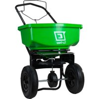
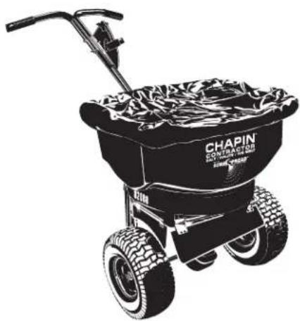
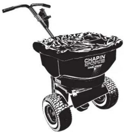
Black-and-white illustration of a CHAPIN agricultural push cart with visible tire tracks and a handle (no text or symbols on the cart itself)Model 82108N
100 lb. Spreader
natural_image
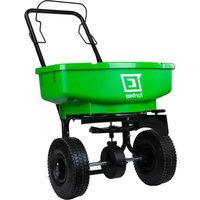
Black-and-white illustration of a pushbar with a basket and handle, no text or symbols visible.Model 82088N
80 lb. Spreader
DO NOT RETURN TO THE STORE
Please call 800-950-4458 if you are missing any parts, having trouble assembling, or have any questions regarding the safe operation of this product.
WARNING
Carefully Read These Instructions Before Use
IMPROPER USE OR FAILURE TO FOLLOW INSTRUCTIONS CAN RESULT IN PRODUCT FAILURE OR INJURIES. FOR SAFE USE OF THIS PRODUCT YOU MUST READ AND FOLLOW ALL INSTRUCTIONS BEFORE USING.
- Do not allow anyone to operate the broadcast spreader without proper instructions
- Do not permit children to operate the broadcast spreader
- Wear protective eyewear and gloves when handling and applying lawn and garden chemicals
- Read the chemical label instructions and warnings for handling and applying the chemicals you plan to spread – application settings provided are only a guideline
ASSEMBLY INSTRUCTIONS
Approximate assembly time is 20-45 minutes
Suggested Tools:
Wrench and/or Ratchet Set
1.5mm Allen Wrench
Pliers
Protective Eyewear
NOTE: Depending on model, this package may contain additional hardware not needed for assembly.
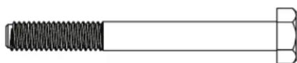
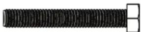
Full scale nuts and bolts

natural_image
Technical line drawing of a bolt with threaded shaft and nut (no text or symbols)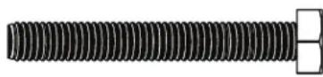
M6 Nylon Locknut (7) M6 x 55mm Hex Bolt (6) M6 x 45mm Hex Bolt (1)

M5 Nylon Locknut (1)
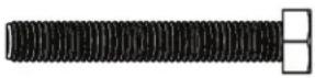
M5 x 35mm Hex Bolt (1)
End Cap (2)
natural_image
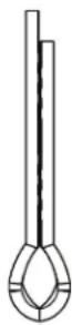
Two concentric circles diagram with no text or symbolsFlat Washer (1)
Cotter Pin (1)
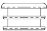
natural_image
Pure technical line drawing of a mechanical assembly (no text or symbols)Bushings (2)
natural_image
Pure diagram of a mechanical component with no text, numbers, or symbolsHand Grip (2)
Step 1:
Attach the right Frame leg and the left Frame leg to the Frame Body using (2) M6x55mm hex bolts and (2) M6 Nylon locknuts per frame leg. After the frame legs have been attached, place the two End caps onto the bottom of both frame legs. DO NOT TIGHTEN DOWN COMPLETELY.
NOTE: Use bottom hole pattern on legs if equipped.
natural_image
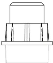
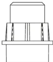
Technical line drawing of a mechanical device with no visible text or symbolsStep 2:
Slide bushings into the holes on the hopper frame from outside of the frame.
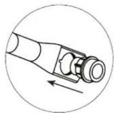
natural_image
Diagram of a mechanical component with directional arrow, no text or symbols present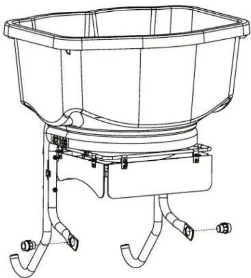
natural_image
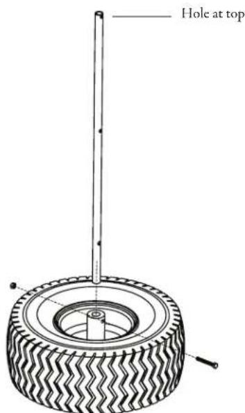
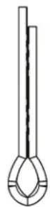
Technical line drawing of a bucket pump assembly with two legs and a central basin (no text or symbols)Step 3:
Insert Axle into Tire as shown and secure using (1) M6 x 45mm Hex Bolt and (1) M6 Nylon Locknut. Take note of hole locations on Axle, to ensure correct orientation.
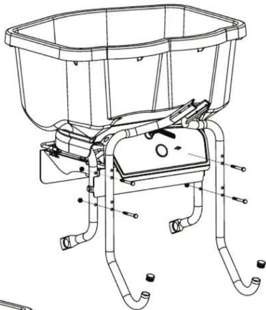
Step 4: Install the Axle/Drive Shaft
a. Slide the Drive shaft through one side of the hopper frame.
b. Slide gearbox onto axle/drive shaft (make sure "FRONT" is facing front of frame as shown) and align middle hole with gearbox.
c. Slide through the other side of the hopper frame. Assemble M5 x 35mm Hex bolt to Axle/Gearbox and secure with M5 Nylon Locknut.
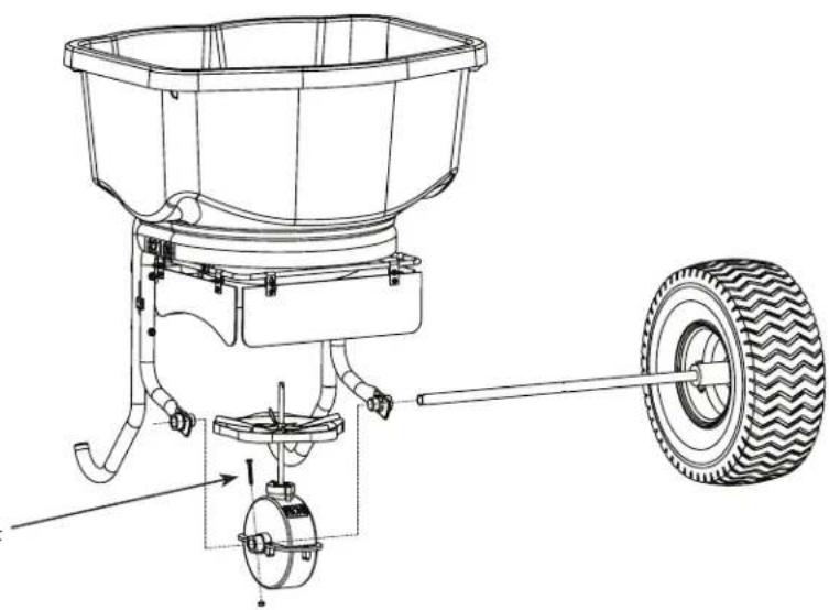
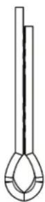
natural_image
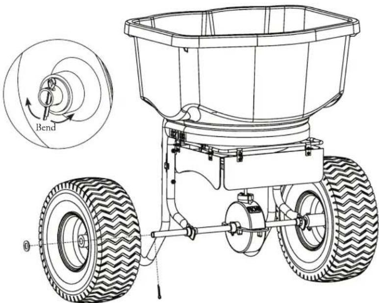
Technical line drawing of a manual sprinkler with a tire, showing components like bucket and wheel assembly (no text or labels)Step 5:
Attach non-drive Wheel onto exposed end of Axle and secure with Flat Washer & Cotter Pin. Slide the Flat Washer onto the Axle until it makes contact with the Wheel, and then slide the Cotter Pin into the hole at the end of the Axle.
Additional Notes:
Drive Shaft: Hole Near Middle should be closer to the right wheel so that the gear box is centered.
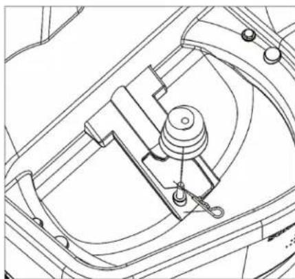
Step 6: Auger Installation
Install auger to impeller shaft. Attach with R-clip.
NOTE: Auger is designed to work in forward motion. Excessive reverse motion could cause binding. If resistance is felt while pulling spreader backwards, stop and clear salt from auger.
natural_image
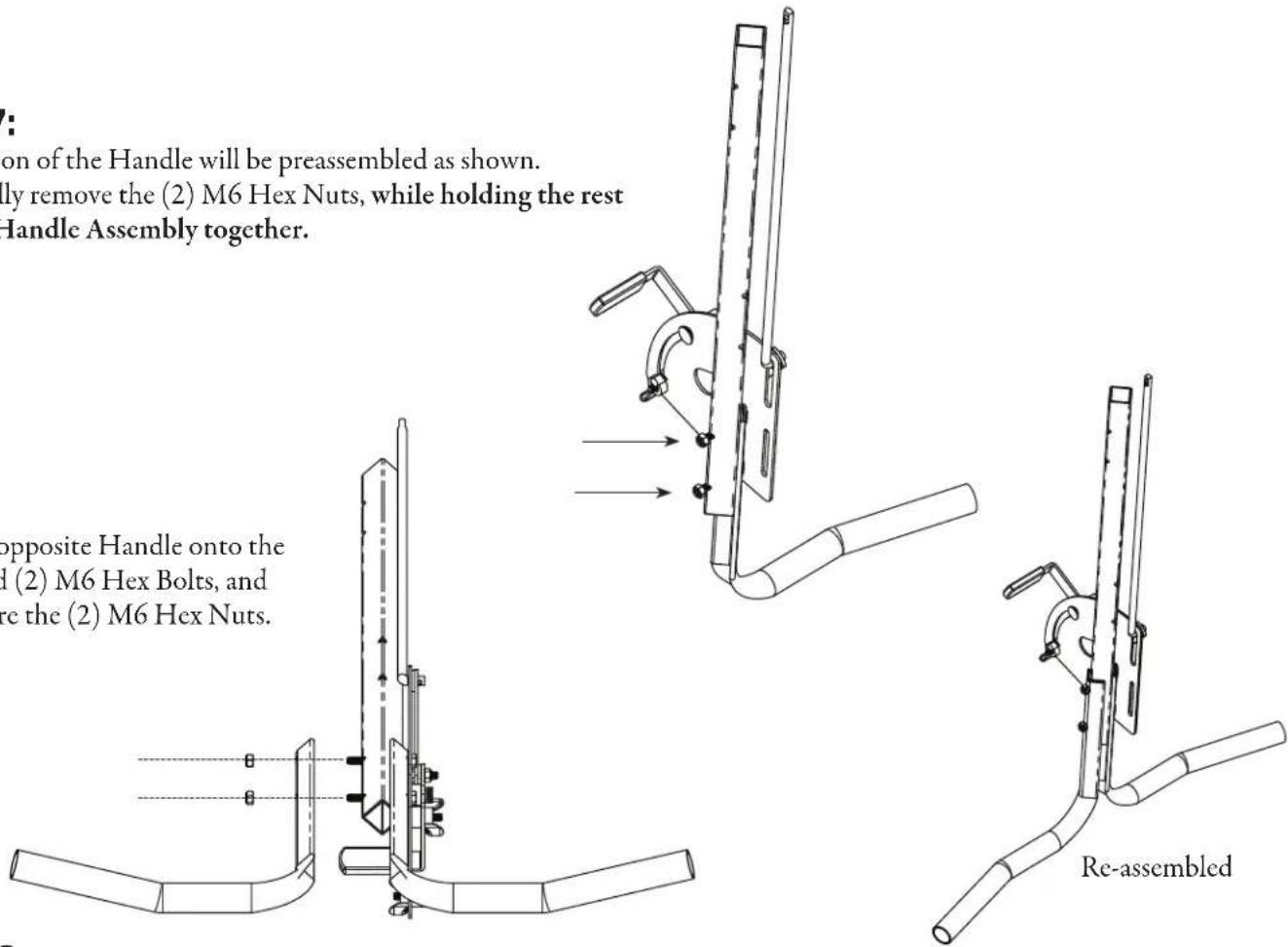
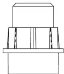
Technical line drawing of a mechanical assembly with no visible text or symbolsStep7:
A portion of the Handle will be preassembled as shown.
Carefully remove the (2) M6 Hex Nuts, while holding the rest of the Handle Assembly together.
Install opposite Handle onto the exposed (2) M6 Hex Bolts, and re-secure the (2) M6 Hex Nuts.
Step 8:
Assemble Handle Tube to Frame Legs by sliding Handle Tube into the gap between the two parts and using (2) M6X55mm bolts and (2) M6 Nylon Locknuts to connect the parts together. Handle orientation is important (see image). Finish tightening frame legs to the frame body.
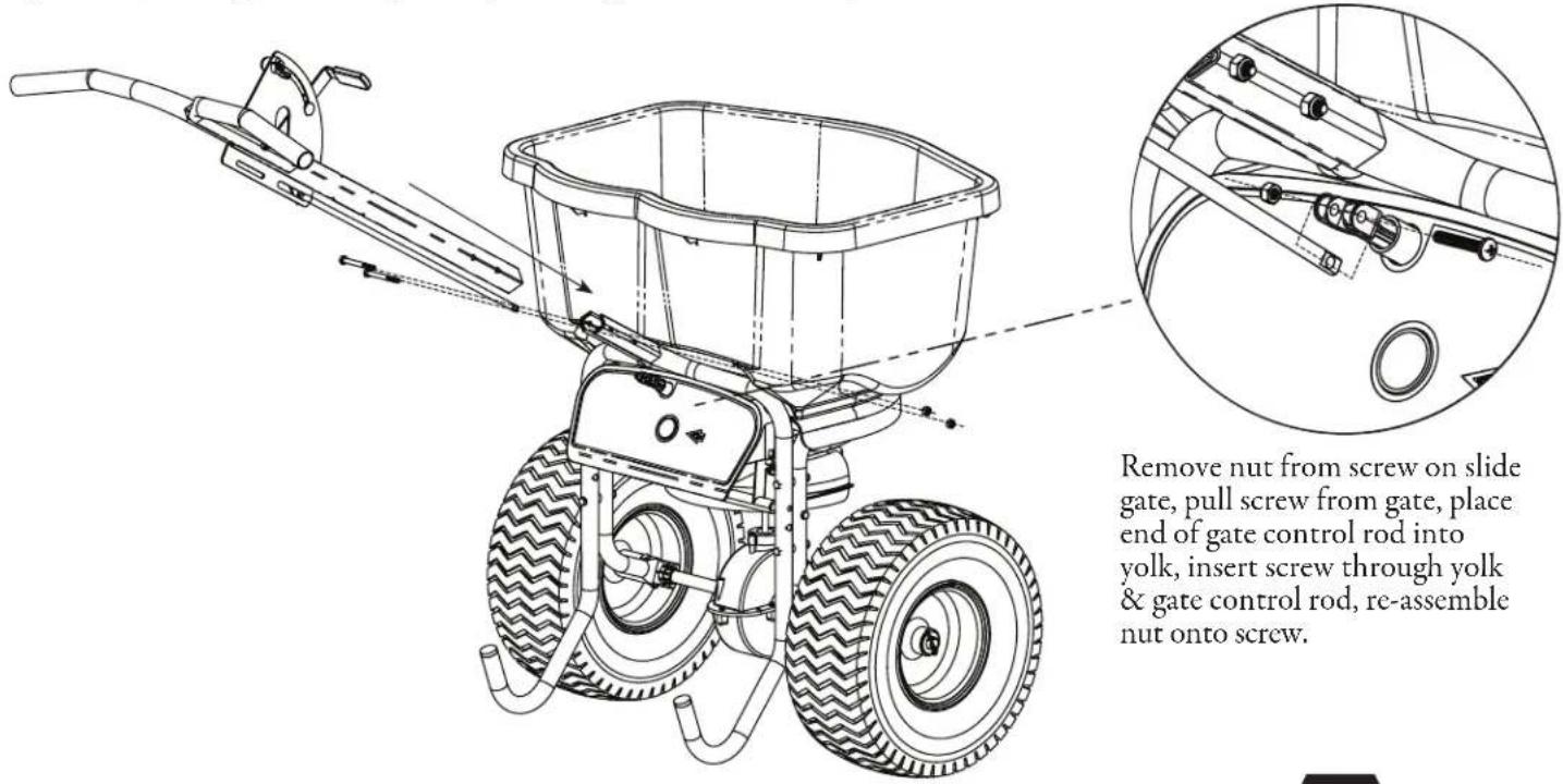
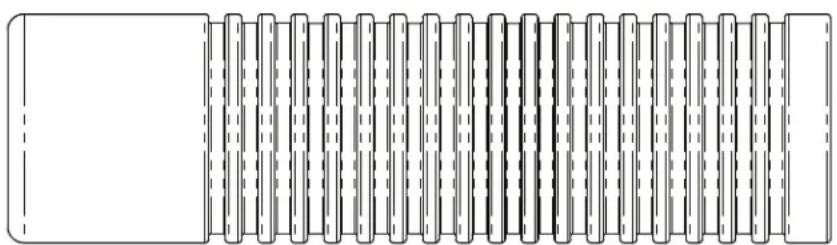
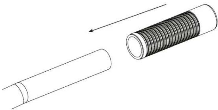
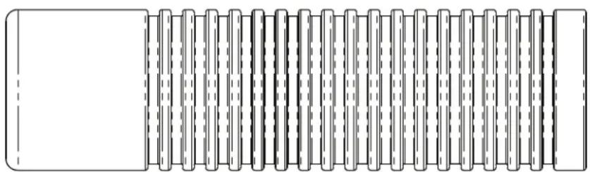
Step 9:
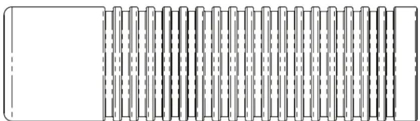
Both Hand Grips slide onto both the left and right handle bars. The Grips should Slide right on.
natural_image
Diagram showing a cylindrical pipe being compressed with a coiled spring, no text or symbols presentGENERAL OPERATING INSTRUCTIONS
- Be sure gate control is in the closed position.
- Determine appropriate setting for material being used by reading the suggested setting on the material's bag.
• To begin spreading, start walking (about 3 mph pace) and pull the gate control down to open gate. - To stop spreading simply push gate control up and the gate will close.
STORAGE AND MAINTENANCE
- When finished spreading empty hopper of any remaining material.
• Thoroughly wash spreader and allow to dry before storing. - Gears are permanently lubricated at the factory. DO NOT open the gearbox at anytime as debris may enter and interfere with functionality.
- When using rock salt and ice-melt products be sure to empty the hopper upon completion of spreading each time you use it. These materials may reconstitute back into a solid block overnight with humidity. They can also damage metal parts if exposed for extended periods of time.
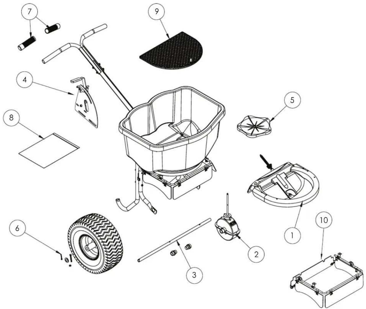
Replacement Parts
| Ref.# | Qty Part No. | Description | |
| 1 1 | 6-9008 Hopper Base Assembly | ||
| 2 1 | 6-9010 Gear Box Assembly | ||
| 3 1 | 6-9009 Drive Shaft w/2 bearings | ||
| 4 1 | 6-9012 Gate Control Assembly | ||
| 5 1 | 6-9014 Impeller | ||
| 6 1 | 6-9015 Wheels w/hardware (red rim) | ||
| 7 1 | 6-9016 Handle Grips | ||
| 8 1 | 6-9017 Hardware Bag | ||
| 9 1 | 6-9001 | Grate | |
| 10 1 | 6-9025 Baffle system | ||
| * | 1 6-9000 Rain Cover | ||
* Not Shown
CHAPIN®
natural_image
Black-and-white illustration of a CHAPIN Progressive Tool Wheatizer with a wheeled cart filled with material, no text or symbols on the diagram itself.Model 82108N 45 kg (100 lb) Esparcidora
natural_image
Black-and-white illustration of a two-wheeled pushrower with a handle and woven basket (no text or symbols visible)Model 82088N 36 kg (80 lb) Esparcidora
NO DEVUELVA A LA TIENDA
natural_image
Technical line drawing of a bolt with threaded shaft and nut (no text or symbols)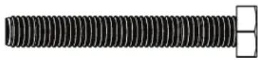
Perno hexagonal M6x45mm (1)

Contratuerca M5 Nylon (1)
Perno hexagonal M5x35mm (1)
Tapa para extremo (2)

natural_image
Two concentric circles diagram with no text or symbolsArandela plana (1)
Chaveta (1)
natural_image
Pure mechanical assembly diagram showing a stepped block and base plate (no text or symbols)Cojinetes (2)
natural_image
Pure diagram of a rectangular object with vertical cylindrical elements, no text or symbols presentEmpuñadura (2)
Paso 1:
natural_image
Technical line drawing of a mechanical device with no visible text or symbolsPaso 2:
natural_image
Diagram of a mechanical component with directional arrow, no text or symbols present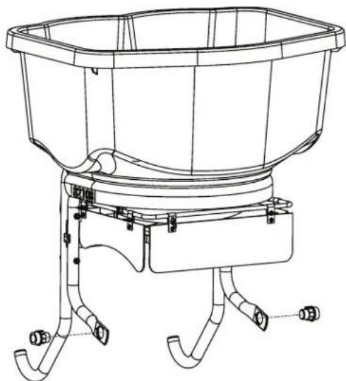
natural_image
Technical line drawing of a bucket with three legs and a handle, no text or symbols presentPaso 3:
natural_image
Technical line drawing of a tire mounted on a stand, showing tread pattern and mounting points (no text or symbols)natural_image
Technical line drawing of a manual sprinkler with a tire, showing components like bucket and wheel assembly (no text or labels)Paso 5:
natural_image
Technical line drawing of a mechanical assembly with no visible text or symbolsPaso 7:
natural_image
Diagram showing a cylindrical pipe being compressed onto a coiled spring, with an arrow indicating compression direction (no text or symbols)Partes de repuesto
natural_image
Black-and-white illustration of a pushbar with wheels and a handle, no text or symbols visible.natural_image
Technical line drawing of a bolt with threaded shaft and nut (no text or symbols)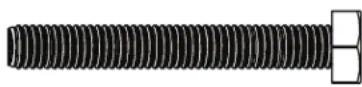
natural_image
Two concentric circles diagram with no text or symbolsRondelle plate (1)
Goupille fendue (1)
natural_image
Pure technical line drawing of a mechanical assembly (no text or symbols)Douilles (2)
natural_image
Pure diagram of a mechanical component with no text, numbers, or symbolsPoignée (2)
Étape 1 :
natural_image
Technical line drawing of a mechanical device with pipes and a central housing (no text or symbols)Étape 2 :
natural_image
Diagram of a mechanical component with directional arrow, no text or symbols present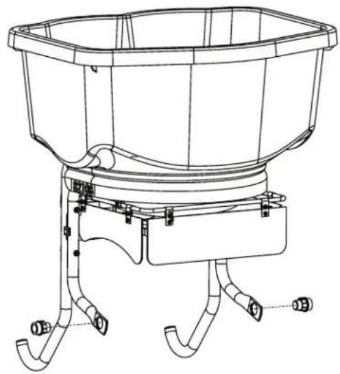
natural_image
Technical line drawing of a bucket with legs and feet, no text or symbols presentÉtape 3:
natural_image
Technical line drawing of a tire with a vertical rod and base, showing tread pattern and mounting points (no text or symbols)natural_image
Technical line drawing of a manual sprinkler with a tire, showing components like bucket and wheel assembly (no text or labels)Étape 5 :
natural_image
Technical line drawing of a mechanical assembly with no visible text or symbolsÉtape 7:
natural_image
Diagram showing a cylindrical pipe being compressed with a coiled spring, no text or symbols presentINSTRUCTIONS D'UTILISATION GÉNÉRALES
Pièces de rechange