
321SP - Electric hedge trimmer HUSQVARNA - Free user manual and instructions
Find the device manual for free 321SP HUSQVARNA in PDF.
| Product type | Gas engine portable sprayer |
| Brand | Husqvarna |
| Model | 321SP |
| Engine | Single-cylinder 2-stroke, air-cooled |
| Displacement | 25.4 cm³ |
| Maximum power | 0.75 kW at 7000 rpm |
| Operating speed | 7000 ± 500 rpm |
| Idle speed | 3000 ± 200 rpm |
| Fuel type | Mixture of unleaded gasoline / 2-stroke oil |
| Mixing ratio | 50:1 (2%) with recommended Husqvarna oil |
| Fuel tank capacity | 0.6 L |
| Pump | Piston type, working pressure 1.5-3.0 MPa |
| Maximum pressure | 3.5 MPa |
| Maximum flow rate | 7 L/min |
| Dimensions (L × W × H) | 332 × 330 × 335 mm |
| Net weight | 9.44 kg |
| Gross weight | 14.5 kg |
| Starting system | Recoil starter with choke and primer |
| Spark plug | LD L7T (gap 0.6-0.7 mm) |
| Supplied accessories | Inlet/return/outlet hoses, spray wands (3 nozzles and 1 nozzle), tools |
Frequently Asked Questions - 321SP HUSQVARNA
User questions about 321SP HUSQVARNA
0 question about this device. Answer the ones you know or ask your own.
Ask a new question about this device
Download the instructions for your Electric hedge trimmer in PDF format for free! Find your manual 321SP - HUSQVARNA and take your electronic device back in hand. On this page are published all the documents necessary for the use of your device. 321SP by HUSQVARNA.
USER MANUAL 321SP HUSQVARNA
EN Operator's manual 2-14
TROUBLE SHOOTING....12
TRANSPORTATION AND STORAGE....13
TECHNICAL DATA....14
ACCESSORIES....14
INTRODUCTION
Operator's manual Intended use
The initial language of this operator's manual is English. Operator's manuals in other languages are translations from English.
Product description
This product is a portable sprayer with a combustion engine. Check with your servicing dealer for more information.
This product has been designed mainly for the purpose of spraying pest control chemicals and weedkillers. Please do not use it for any other purposes or tasks, as this may cause unforeseen accidents.
Note: National or local regulations may regulate the use. Comply to given regulations.
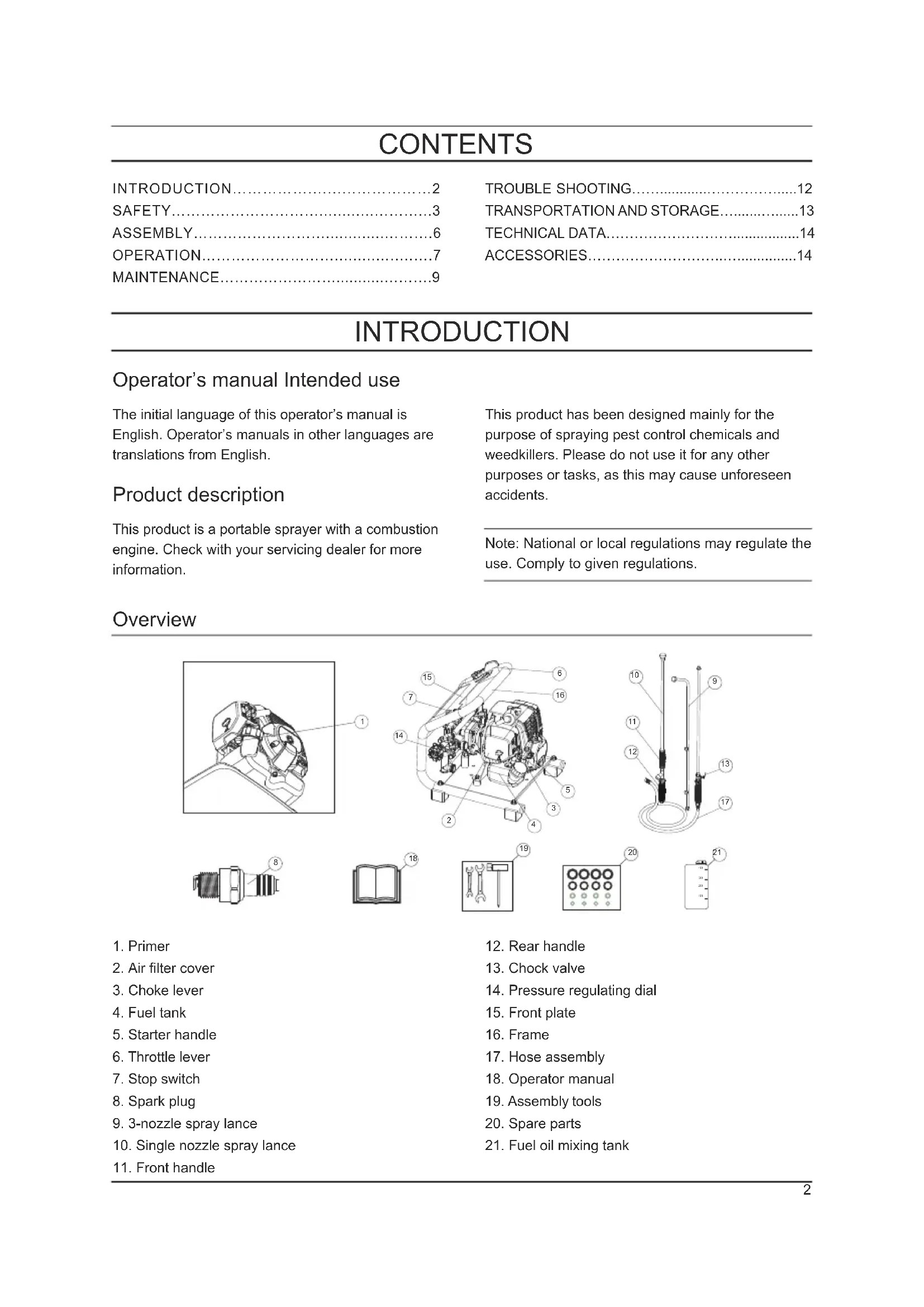
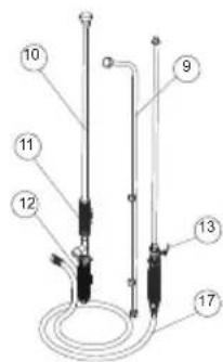
Overview

natural_image
Technical line drawing of a mechanical component with labeled part (1), no readable text or symbols present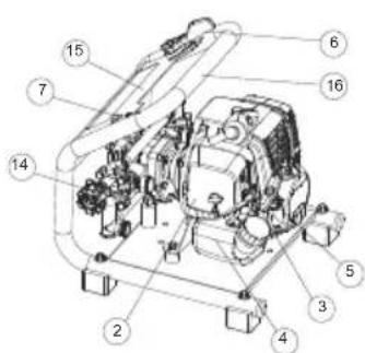


-
Primer
-
Air filter cover
-
Choke lever
-
Fuel tank
-
Starter handle
-
Throttle lever
-
Stop switch
-
Spark plug
-
3-nozzle spray lance
-
Single nozzle spray lance
-
Front handle
-
Rear handle
-
Chock valve
-
Pressure regulating dial
-
Front plate
-
Frame
-
Hose assembly
-
Operator manual
-
Assembly tools
-
Spare parts
-
Fuel oil mixing tank
Symbols on the product

Read this manual before operating Primer

Wear protective headgear, protective goggles, ear muffs and protective mask

Wear rubber boots

Wear protective clothing

Wear rubber gloves

Electric shock

Hot surface

High pressure injection

Keep safe distance

The port to refuel the MIX GASO-LINE

The direction to close the choke

The direction to open the chok

Low speed

High speed

Note: Other symbols/decals on the product refer to certification requirements for other commercial areas.
Product liability
As referred to in the product liability laws, we are not liable for damages that our product causes if:
• the product is incorrectly repaired.
• the product is repaired with parts that are not from the manufacturer or not approved by the manufacturer.
• the product has an accessory that is not from the manufacturer or not approved by the manufacturer.
• the product is no repaired at an approved service center or by an approved authority
SAFETY
Safety definitions
The definitions below give the level of severity for each signal word.

WARNING: Injury to persons.

CAUTION: Damage to the product.
Note: This information makes the product easier to use.
General safety instructions

WARNING: Read the warning instructions that follow before you use the product.
- Use the product correctly. Injury or death is a possible result of incorrect use. Only use the product for the tasks found in this manual. Do not use the product for other tasks.
- Read, understand and follow the instructions and the symbols in this manual. If the operator does not follow the instructions and the symbols, injury, damage or death is a possible result.
- Do not discard this manual. Use the instructions to assemble, to install attachments and accessories, to operate and to maintain. Only use approved attachments and accessories.
- It is not possible to give warning on every situation that can occur during operation and maintenance of the product. Always be careful and use your common sense.
• Make sure that parts are not damaged before you use the product. Follow the maintenance schedule. Only do the maintenance work that instructed in this manual. An approved service center must do all other maintenance work. - Do not operate the product or do maintenance on the product if you are not sure of the situation. Turn to the approved dealer, service agent or service center for information.
- Disconnect the spark plug cable before assembly, storage or maintenance of the product.
- Do not use the product if it is changed from its initial specification. Do not change any part of the product without approval from the manufacturer. Only use parts approved by the manufacturer. Injury or death is a possible result of incorrect maintenance.
- Do not breathe in the fumes from the engine. Long-term inhalation of the engine exhaust fumes is a health risk.
- Do not start the product indoors or near flammable material. The exhaust fumes is hot and contain spark which can start a fire. Not sufficient airflow can cause injury or death because of asphyxiation or carbon monoxide.
- When you use this product the engine makes an electromagnetic field. The electromagnetic field can cause damage to medical implants. Check with your physician and medical implant manufacturer before you use the product.
- Do not let a child or a person without knowledge of the instructions operate the product.
- Make sure that you always monitor a person, with decreased physical capacity or mental capacity, that uses the product. A responsible adult must be there at all times.
- Lock the product in an area that children and unapproved persons cannot access.
- The product can eject objects and cause injuries. Obey the safety instructions to decrease the risk of injury or death.
- Do not leave the product when the engine is on.
- The operator of the product shall be responsible for any accident occurs.
- Make sure that you are minimum 15 m (50 ft) away from other persons or animals before you use the product. Make sure that persons in the adjacent area know that you will use the product.
- Refer to national or local laws. They can prevent or decrease the operation of the product in some conditions.
- Do not use the product if you are fatigued or influenced by alcohol, drugs or medicine. They can have effects on your vision, alertness, coordination or judgment.
Safety instructions for operation
- Make sure the product is fully assembled before using it.
- Put the product on an even ground 3 m (10 ft) away from the position where you filled the fuel tank before starting the engine.
- The product can cause objects to eject, which can cause damage to the eyes. Always use an approved eye protection when you operate the product.
- Be careful, a child can come near the product without your knowledge during operation.
- Do not operate the product if there are persons in the work area. Stop the product if a person goes into the work area.
- Make sure that you are always in control of the product.
- Do not use the product if you cannot receive aid in case of an accident. Always make sure others know you will operate the product before you start.
- Do not turn with the product before you make sure that no persons or animals are in the safety area.
- Remove all unwanted materials from the work area before you start.
- Do not use the product in bad weather like fog, rain, strong winds, risk of lightning or other weather conditions. Dangerous conditions such as slippery surfaces can occur because of bad weather.
- Make sure that you can move freely and work in a stable position.
- Make sure that you cannot fall when you use the product. Do not tilt when you operate the product.
- Do not touch the bevel gear which is hot and can cause injury after the engine stops.
- Stop the engine before you move the product.
Chemical filling
- Chemical substances should be handled correctly, or it can cause serious poisoning or even fatal accidents. Always observing the warning symbols on the container, since some chemicals are extremely hazardous to humans and animals.
- Chemical substance containers should be stored separately from other containers with obvious warning symbols and out of the reach of children.
Personal protective equipment Fuel

WARNING: Read the warning instructions that follow before you use the product.
• Always use correct personal protective equipment when you operate the product. The personal protective equipment does not erase the risk of injury but just decreases the grade of injury if an accident occurs.
• Always use an approved eye protection while you operate the product.
- Do not operate the product with bare feet or with open shoes. Always use heavy-duty slip-resistant boots.
- Use heavy, long pants.
- If it is necessary, use approved protective gloves.
- Use a helmet if it is possible that objects fall on your head.
- Always use approved ear protection while you operate the product. Noise for a long period can cause noise-induced hearing loss.
- Make sure that you have a first aid kit nearby.
Protective devices on the product
- Make sure that you regularly do the maintenance to the product.
• The life of the product increases.
• The risk of accidents decreases. - Let an approved dealer or an approved service center regularly examine the product to do adjustments or repairs.
- Do not use a product with damaged protective equipment. If the product is damaged, speak to an approved service center.
Check valve and throttle trigger
- Before start the engine, make sure the check valve is at the off position and the throttle trigger at the turtle position. Start with the check valve pulled out is dangerous, as chemical fluid may spray out of the nozzle when the engine is started.
Stop switch
- Start the engine. Make sure that the engine stops when you press the stop switch.
- Do not start the product if there is fuel or engine oil on the product. Remove the unwanted fuel or oil and let the product dry.
- If you spill fuel on your clothing, change clothing immediately.
- Do not get fuel on your body, which can cause injury. If you get fuel on your body, use a soap and water to remove the fuel.
- Do not start the engine if you spill oil or fuel on the product or on your body.
- Do not start the product if the engine has a leak. Examine the engine for leaks regularly.
- Be careful with fuel. Fuel is flammable and the fumes are explosive and can cause injuries or death.
- Do not breathe in the fuel fumes, it can cause injury. Make sure that there is a sufficient airflow.
- Do not smoke nor put warm objects near the fuel or the engine.
- Do not add fuel when the engine is running. Make sure the engine is cool before you refuel.
- Before you refuel, open the fuel tank cap slowly and release the pressure carefully.
- Do not add fuel to the engine in an indoor area. Not sufficient airflow can cause injury or death because of asphyxiation or carbon monoxide.
- Tighten the fuel tank cap carefully or a fire can occur.
- Move the product at a minimum of 3 m (10 ft) away from the position where you filled the tank before a start.
- Do not fill too much fuel in the fuel tank.
- Make sure that a leak cannot occur when you move the product or fuel container.
- Do not put the product or a fuel container where there is an open flame, spark or pilot light. Make sure that there is no flame within the storage area.
- Only use approved containers when you move the fuel or put the fuel into storage.
- Clean the product and empty the fuel tank before long-term storage. Obey the local law on where to dispose fuel.
- Remove the spark plug cable before you put the product into storage to make sure that the engine does not start accidentally.
Safety instruction for maintenance
- In order to maintain the functions of the product, regularly carry out the maintenance inspections listed in this manual. Please consult approved product supplier or nearest Husqvarna product dealer if maintenance or parts replacement are required but not listed in this Manual.
- Never keep the engine running while carrying out inspections or maintenance.
- Do not modify the product or dismantle the engine. This could lead to breakdown and serious accidents during operation.
- Do not touch the muffler or spark plug with bare hands immediately after stopping the engine, since the high temperature can cause burns.
- Use original Husqvarna replacement parts or brands designated by Husqvarna
ASSEMBLY
To connect inlet hose To connect outlet hose

WARNING: Only use approved inlet hose, since other hose may damage the pump.
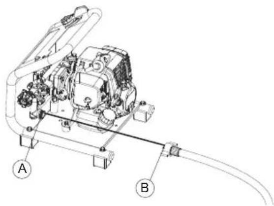
- Attach the inlet hose to the pump inlet (A) by tightening the wing nut (B). Tighten by hand only as overtightening may damage hose fittings.
To connect return hose

- connect the return hose (E) to fitting (C) and tighten by clamp (D).
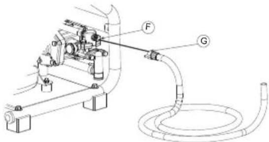
- Attach the spray hose to the pump outlet (F) by tightening the wing nut (G). Tighten by hand only as overtightening may damage hose fittings.
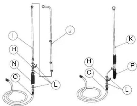
To connect spray lance
-
For 3-nozzle spray lance: Fasten the extended lance (I) to the chock valve (H). Fasten the 3-nozzle spray (J) to the extended lance (I). Ensure all connections are secured. Tighten by hand only.
-
For single nozzle lance: Fasten the single nozzle lance (K) to the chock valve (H). Ensure the connection is secured. The single nozzle lance is equipped with the flow adjustment. Tighten by hand only.
Note: If there is a leakage from the single nozzle lance (K) fittings, retighten the fittings with a spanner or multigrip.
- After the spray hose assembly is connected with
the spray lance, inspect and ensure all connections in the spray hose assembly such as the seals (L), chock valve (H), handle (N), spray hose (O) and rear handle (P) are tightly secured. Tighten by hand only.
OPERATION

WARNING: Read, and understand the safety chapter before you operate.
To use fuel

CAUTION: This product has a two-cycle engine. Use a mixture of gasoline and two-cycle engine oil. Make sure to use the correct quantity of oil in the mixture. Incorrect ratio of gasoline and oil can cause damage to the engine.
Gasoline

CAUTION: Do not use gasoline with an octane number less than 90 RON (87 AKI). This can cause damage to the product.

CAUTION: Do not use gasoline with more than 10% ethanol concentration (E10). This can cause damage to the product.

CAUTION: Do not use leaded gasoline. This can cause damage to the product.
• Always use new unleaded gasoline with a minimum octane number of 90 RON (87 AKI) and with less than 10% ethanol concentration (E10).
- Use gasoline with a higher octane number if you frequently use the product at continuously high engine speed.
• Always use a good quality unleaded gasoline/oil mixture.
Two-cycle engine oil
- Use only the two-cycle engine oil of high quality, especially HUSQVARNA two-cycle engine oil. Use only the oil of an air cooled engine.
-
Mixture ratio 50:1 (2%).
-
Oil of low quality and high oil/fuel ratio can decrease the lifetime of catalytic converters.
- Check with the approved dealer when you select an oil.
- If Husqvarna two-stroke oil is not available, you can use another two-stroke oil of good quality that is intended for air cooled engines.
- Do not use the two-stroke oil for water-cooled outboard engines. The two-stroke oil is sometimes referred to as outboard oil.
| Gasoline, liter | Oil, liter |
| 2% (50:1) | |
| 5 | 0.1 |
| 10 | 0.2 |
| 15 | 0.3 |
| 20 | 0.4 |
To mix the fuel
Note: Always use a clean fuel container when you mix the fuel. Do not use fuel mixture made over 30 days.
- Add half of the gasoline.
- Add all of the oil.
- Shake the fuel mixture to mix.
- Add the remaining half of gasoline.
- Shake the fuel mixture again to mix.
- Fill the fuel tank.
To filling the fuel tank
- Make sure that the fuel mixture is correct and is in a fuel container with an antispill valve.
-
If fuel is on the container, remove the unwanted fuel and let the container dry.
-
Make sure that the area near the fuel tank cap is clean.
- Remove the fuel tank cap.
- Shake the fuel container before you add the fuel mixture to the fuel tank.
- Put back the fuel tank cap.
To start and stop
Before you start the engine
- Examine the product for missing, damaged, loose or worn parts.
- Examine the nuts, screws and bolts.
- Examine the air filter.
- Examine the check valve and throttle trigger.
- Examine the stop switch.
- Examine the product for fuel leaks.
- Examine the inlet hose, inlet filter, outlet hose, return hose and spray lance for correct connection.
To start a cold engine

WARNING: Do not touch the cover or use a product with damaged spark plug cap. It can burn your skin and cause electrical shock if the spark plug cap is damaged.

CAUTION: Do not pull all the starter rope out. Hold the starter rope handle when it is fully extended. Do not twist the starter rope around your hand.
- Press the air purge ten times.
- Move choke lever to the choke position.
- Place the product to the even ground. Pull out the starter rope slowly until you feel some resistance. Pull the starter rope quickly and with force. Keep doing it until you hear the engine start.
- Set the choke lever to the run position, then pull the starter rope until the engine starts.
- Pull the throttle trigger slightly and run at low speed for 60 seconds.
To start a warm engine
- Press the air purge ten times.
- Set the choke lever to the run position, then pull the start rope until the engine starts.
To stop the engine
- Press the stop switch to stop the engine.
To spray
- Do not wind the hoses to the product body in any way, or hoses will be burnt or damaged
- Please use correctly, observing the precautions in this manual.
- When spraying, do not point the nozzle at your face, or at other people, animals, etc.
- If the chemical liquid runs out when spraying, put the engine to low speed immediately. Empty running of the engine may cause the spray pump to break.
- Please avoid using multiple nozzles, jet nozzles, or other nozzles that give a large spray volume, as spraying efficiency is sometimes impaired owing to insufficient pressure.
Spray procedure
Note: Start the engine and wait about 30 seconds to empty air in the pump every time when using the product.
- Set the chock valve to close position
- Start the engine.
- Increase the engine speed.
- Open the chock valve (H).
- Wait about 30 seconds or longer until the chemical fluid starts to spray out from the nozzle in the form of mist.
- When stopping work, close the cock valve (H) fully and reduce the engine speed.
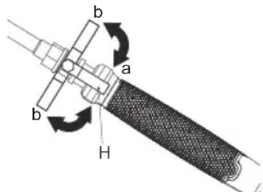
a. open b. close
Cleaning after spraying
- Fill in about 5L of clean water into spray tank.
- Spray through the nozzle for 2-3 minutes, and drain the water left inside the tank.
MAINTENANCE

WARNING: Read and understand the safety chapter before you clean, repair or do maintenance on the product.
To check the air cleaner
• After every 25 hours of operation, please remove the air cleaner cover and inspect the air cleaner. If it is too dirty, wash it carefully in warm water containing a neutral detergent, and put it back to its original position after drying it thoroughly.
- If the air cleaner is distorted or damaged, please replace it with a new one.
- If the air cleaner is blocked, the efficiency of the engine will be reduced. In addition, the engine interior will suffer abnormal wear if it is operated without filter or if continually operated with a distorted or damaged filter.
To check the fuel filter
• After every 25 hours of operation, empty the fuel tank, detach the fuel filter from the tank, and remove all dirt. If the filter is too clogged, please replace it with a new one.
- If the fuel filter is clogged, the engine speed may be limited or speed fluctuations may occur.
- If the engine is operated without a fuel filter, dirt will accumulate in the carburetor and cause it to malfunction
To check the spark plug
- Do not touch the spark plug with your bare hands immediately after operation, as there is the risk of burns due to high temperature.
- After every 25 hours of operation, detach the spark plug and remove dirt from the electrodes with a wire brush or similar.
- The correct electrode gap is 0.6 to 0.7mm .
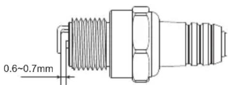
- When replacing plugs, please use designated items.
- If too much fuel is absorbed or poor quality oil is used, the spark plug electrodes become dirty, making the engine harder to start.
- Note that using any spark plug other than those designated may result in the engine failing to operate properly or in the engine becoming overheated and damaged.
- To install the spark plug, first turn the plug until it is finger tight, then tighten it a quarter turn more with a socket wrench.
TIGHTENING TORQUE: 14.7 to 21.6 N.m. (150 to 220 kgf-cm)
To check the spray nozzle
- A clogged spray nozzle can cause the spray pressure and flowrate to drop. All excessive pressure will go back to the sprayer tank.
To correct the problem, immediately clean the spray tip by following these instructions:
- Stop engine & remove the unit from the operators back.
- Disconnect the spray rod from the spray hose assembly.
- To remove the nozzle cap, turn in anticlockwise direction.
- Inspect and clean the spray tip and metal strainer for 3-nozzle spray rod from any foreign material clogging or restricting the spray nozzle. Replace if damaged.
- Reinstall the nozzle cap and the spray rod with the spray hose assembly tightly (hand tighten).
To check the pump oil level
- Oil level should be checked prior to each use.
- Make sure the sprayer is on an even surface.
- Verify the oil is showing as 1/3-1/2's full (approx. 100ml) in the oil glass window.
Note: Do not attempt any oil maintenance on this pump. The pump is pre-lubricated and sealed from the factory. If refilling is required, see an authorized dealer or service centre.
To check the muffler

WARNING: Inspect periodically, the muffler for loose fasteners, any damage or corrosion. If any sign of exhaust leakage is found, stop using the machine and have it repaired immediately. Note that failing to do so may result in the engine catching on fire.
Perform the procedures after every 100 hours of operation:
- Remove the muffler, insert a screwdriver into the vent, and wipe away any carbon buildup. Wipe away any carbon buildup on the muffler exhaust vent and cylinder exhaust port at the same time.
- Tighten all screws, bolts, and fittings.
- Check and wipe off if any oil or grease left in between the clutch lining and drum with oil-free and lead-free gasoline.
To check the cooling system

WARNING: Never touch the cylinder, muffler, or spark plug with your bare hands immediately after stopping the engine. The engine can become very hot when in operation, and doing so could result in severe burns.
- When checking the product to make sure that it is in good condition before using it, check the area around the muffler and remove any staffs that attached, in case the muffler is overheated or even the engine catch on fire.
Maintenance schedule
- Check the intake air cooling vent and the area around the cylinder cooling fins for blockage every 25 hours of use, in case of engine overheat or even product failure. Note that it is necessary to remove the upper cover and the lower cover in order to be able to view the upper part of the cylinder.
To check the grease cups
- Open the upper cap of the grease cup and check the grease amount. Fill it up if it decreased.
To adjust engine speed
- Although the engine is adjusted before leaving the factory, it may require readjustment or maintenance after repeated use. Please consult the original supplier regarding inspections and maintenance other than those shown below.
To adjust engine speed
Note: Warm up the engine before adjusting the idle speed.
- If the engine stops or the pump continues to work at idle speed with the throttle trigger at the turtle position, readjust the engine speed with the idle speed adjustment screw on the left of the carburetor.
Turn the idle adjustment screw: - Counter-clockwise to reduce engine speed
- Clockwise to increase engine speed
To replace gear oil
• After first 25 hours of use, replace the gear oil. After that, replace it after every 100 hours of use (SAE90, 100cc).
Note: Make sure you obey the maintenance schedule. The intervals are calculated from daily use of the product. The intervals are different if you do not use the product each day. Only do the maintenance work that is found in this manual. Speak to an approved service center about other maintenance work not found in this manual.
| Maintenance procedure | Daily | Weekly Monthly Note | |
| Overall | |||
| Inspect the whole unit for damage,leakage or spillage | √ | ||
| Inspect all accessible fasteners Tighten or replace if necessary | |||
| Inspect all screws/nuts/bolts | √ | Tighten or replace if necessary.Adjusting screws are not included. | |
| Check the hoses and fittings | √ | ||
| Clean for any debris | √ | ||
| Engine | |||
| Inspect and clean the fuel tank | √ | ||
| Inspect and clean the fuel filter | √ | ||
| Inspect and clean the air cleaner | √ | ||
| Check the operation of the throttle lever and stop switch | √ | ||
| Empty the fuel tank | √ | ||
| Apply grease to the plunger | √ | ||
| Clean or re-adjust the spark plug gap | √ | Make sure the gap is 0.6-0.7mm (.025in).Replace if necessary | |
| Inspect the muffler for damage. | √ | Replace if necessary | |
| Clean the muffler and the cylinder exhaust port | √ | ||
| Clean the cylinder fins and intake air cooling fan | √ | ||
| Spray nozzles and chemical filter | |||
| Clean chemical filter | √ | ||
| Check the spray nozzles | √ | ||
| Pump | |||
| Check the level of the pump oil | √ | ||
| Replace the gear oil | √ | ||
| Check the grease cups | √ | ||
| Clean the pump | Spray 5L of clean water to clean the pump after use | ||
TROUBLE SHOOTING
Trouble shooting
If running difficulties continue, contact your closest Authorized Dealer or Service Centre.
| Problem Possible causes Remedy | ||
| Engine will not start | Electrode spark plug is wet or fouled | Clean or replace the spark plug |
| Cracked spark plug insulator | Replace the spark plug | |
| Engine flooded | Crank engine with choke open and full throttle to clear excess fuel | |
| Incorrect or stale fuel | Drain and replace with correct fuel/oil mixture | |
| No fuel in tank | Refuel with correct fuel/oil mixture | |
| Insufficient power | Clogged air cleaner | Clean and lubricate air cleaner |
| Fuel line/passage clogged | Contact Service Centre or see authorized dealer | |
| Carbon build up in muffler | Contact Service Centre or see authorized dealer | |
| Use incorrect or stale fuel | Drain and replace with correct fuel/oil mixture | |
| Piston seizure | Contact Service Centre or see authorized dealer | |
| Machine is overworked | Operate properly - do not overload | |
| Engine stops during operation | Switch is bumped | Restart the engine |
| Shorting of spark plug | Clean spark plug or replace | |
| Piston scored | Contact Service Centre or see authorized dealer | |
| Fuel tank is empty | Refuel with correct fuel/oil mixture | |
| Carburetor or fuel tank clogged | Contact Service Centre or see authorized dealer | |
| Engine is difficult to stop | Stop wire disconnected from the switch | Attach stop wire to switch |
| Overheated engine | Contact service Centre or see authorized dealer | |
| Unit main body | Loose engine and/or pump mounts | Retighten engine and/or pump mount screws |
| Leak at the tube connections | Retighten the hose clip or replace if damaged | |
| Pump is no spraying | No chemical diluted liquid in the sprayer tank | Fill the sprayer tank |
| Valves inside the pump clogged | Contact Service Centre or see authorized dealer | |
| Cock valve blocked | Clean the cock valve or replace | |
| Incorrect pressure setting too low | Adjust the pressure regulating dial | |
| Pump is worn out or damaged | Contact Service Centre or see authorized dealer | |
| Spray rod nozzle clogged | Clean the nozzle | |
| Insufficient spray pressure | Pump speed or pressure setting too low | Adjust the pump speed and pressure regulating dial |
| Spray rod nozzle clogged | Clean the nozzle | |
| Pump seals and/or vee-packing seals worn or damaged | Contact Service Centre or see authorized dealer | |
| One way valve(s) inside the pump clogged | Contact Service Centre or see authorized dealer | |
| Clutch slipping | Replace the clutch | |
| Lack of lubrication | Apply grease onto the plunger | |
| Burst spray hose | Contact Service Centre or see authorized dealer | |
| Spray rod nozzle worn or dam-aged | Contact Service Centre or see authorized dealer | |
TRANSPORTATION AND STORAGE
Transportation
- Keep equipment safe during transportation to prevent damage and accidents.
- Keep the product and equipment in a dry and frost-proof area.
• Empty the fuel and clean the product. - Replace or repair damaged components.
- Use the correct protective cover on the product that does not keep moisture.
- Keep the product tightly attached during transport.
Storage

WARNING: When draining fuel, please be careful not to spill it. If fuel is spilt, wipe off thoroughly. In addition, please be sure to close the storage container cap tightly.

CAUTION: If fuel is left in the engine for protracted periods, the inside of the carburetor may become clogged and cause engine faulty starting and insufficient output.
- During storage, slightly loosen the cap of the chemical fluid tank. If screwed too tightly, the gasket may become distorted.
On completion of all work procedures with no plan to use the product again for a protracted period, please carry out the following pre-storage care to prevent trouble caused by time-lapse changes.
- Clean the chemical fluid tank and nozzle.
- Remove dirt from the sprayer and check for any damage or looseness. If any abnormality is found, correct it thoroughly in preparation for future use of the unit.
- Drain the fuel tank.
- Start the engine, and leave it at idle speed until all the fuel inside the carburetor is consumed and the engine comes to a natural stop.
- Remove the spark plug and put a few drops (1 to 2 cc) of 2-cycle oil inside the engine. After pulling the starter rope 2 or 3 times, return the spark plug to its original position and stop in compressed position.
- After oiling the throttle trigger and other metal parts with anti-corrosive oil, cover the product and store indoors in a low-humidity location.
TECHNICAL DATA
Technical data
| Product model 321SP | ||
| Pump | Type | Plunger type |
| Working Pressure (MPa) | 1.5-3.0 | |
| Max. Pressure (MPa) | 3.5 | |
| Max. Working Flowrate (LPM) | 7 | |
| Engine | Type | Single-cylinder air-cooled 2-stroke gasoline engine |
| Engine Displacement (cc) | 25.4 | |
| Max. Power/Speed (kW/rpm) | 0.75/7000 | |
| Engine Operating Speed (rpm) | 7000±500 | |
| Idling Speed (rpm) | 3000±200 | |
| Fuel Type | Gasoline/Oil Mixture | |
| Oil | 2-strok oil | |
| Admixture ratio | 25:1,40:1(Only Husqvarna genuine oil) | |
| Starter system | Easy starter | |
| Spark plug | LD L7T | |
| External dimensions of main unit (mm) L*W*H: | 332*330*335 | |
| Net weight / Gross weight (kg) | 9.44 / 14.5 | |
| Capacity of fuel tank (L) | 0.6 | |
ACCESSORIES
Accessories
| Name Spec. | |
| Inlet hose | Length 2.5m, G1/2 14 |
| Return hose | Length 2.5m, dia. 8mm |
| High pressure outlet hose | Length 15m, M14*1.5 |
ÍNDICE
INTRODUCCIÓN....15
SEGURIDAD....16
MONTAJE....19
FUNCIONAMIENTO....21
MANTENIMIENTO....23
DONNÉES TECHNIQUES....62
ACCESSOIRES....62
INTRODUCTION
natural_image
Technical line drawing of a mechanical component with labeled part (1), no readable text or symbols present


natural_image
Technical line drawing of a mechanical component with labeled part (1), no readable text or symbols present

natural_image
Technical line drawing of a mechanical component with labeled part (1), no readable text or symbols present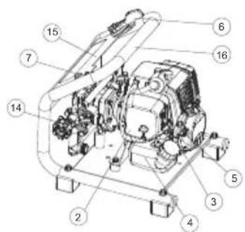


لفحص أكواب الشحوم
产品操作

警告:操作前请仔细阅读并理解安全须知。
使用燃油

检查燃油滤清器
Original instructions
2022-3-31
- INTRODUCTION
- Operator's manual Intended use
- Product description
- Overview
- Symbols on the product
- Product liability
- SAFETY
- Safety definitions
- General safety instructions
- Safety instructions for operation
- Chemical filling
- Personal protective equipment Fuel
- Protective devices on the product
- Check valve and throttle trigger
- Stop switch
- Safety instruction for maintenance
- ASSEMBLY
- To connect inlet hose To connect outlet hose
- To connect return hose
- To connect spray lance
- OPERATION
- To use fuel
- Gasoline
- Two-cycle engine oil
- To mix the fuel
- To filling the fuel tank
- To start and stop
- Before you start the engine
- To start a cold engine
- To start a warm engine
- To stop the engine
- To spray
- Spray procedure
- Cleaning after spraying
- MAINTENANCE
- To check the air cleaner
- To check the fuel filter
- To check the spark plug
- To check the spray nozzle
- To check the pump oil level
- To check the muffler
- To check the cooling system
- Maintenance schedule
- To check the grease cups
- To adjust engine speed
- To replace gear oil
- TROUBLE SHOOTING
- TRANSPORTATION AND STORAGE
- Transportation
- Storage
- TECHNICAL DATA
- ACCESSORIES
- ÍNDICE
- 产品操作
- 使用燃油
- 检查燃油滤清器
Brand : HUSQVARNA
Model : 321SP
Category : Electric hedge trimmer