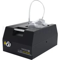
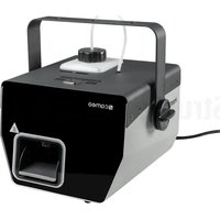
Instant Fog 1700 Pro - Effect machine Cameo - Free user manual and instructions
Find the device manual for free Instant Fog 1700 Pro Cameo in PDF.



| Product Type | Professional Fog Machine |
| Brand | Cameo |
| Model | Instant Fog 1700 Pro |
| Dimensions (W x H x D) | 325 x 235 x 476 mm |
| Weight (without tank) | 14.9 kg |
| Operating Voltage | 230 V AC / 50-60 Hz |
| Power Consumption | 1800 W |
| Fuse | T10AL (5x20 mm) |
| Warm-up Time | Approx. 7 minutes |
| Control | DMX-512 (3 channels and 1 channel), Standalone, Timer, Slave |
| DMX Connectors | XLR 3-pin and 5-pin (input/output) |
| Display | Backlit LCD screen, 2 lines |
| Control Elements | Mode, Enter, Up, Down buttons; Instant Fog function (MODE+UP) |
| Protection | Overheat (thermostat), low liquid protection |
| Housing Material | Metal |
| Color | Black |
| Included Accessories | Power cable, adapter for 100 mm hose, special tank cover with ventilation valve and suction hose |
| Option | FLYKIT (available as option) |
| Liquid Compatibility | Exclusively Cameo water-based fog liquid |
| Tank Capacity | 5 liters |
| Maintenance | Clean evaporator system every 60 hours with Cameo cleaning liquid |
| Operating Ambient Temperature | 5 °C to 40 °C |
| Relative Humidity | < 85 % (non-condensing) |
Frequently Asked Questions - Instant Fog 1700 Pro Cameo
User questions about Instant Fog 1700 Pro Cameo
0 question about this device. Answer the ones you know or ask your own.
Ask a new question about this device
Download the instructions for your Effect machine in PDF format for free! Find your manual Instant Fog 1700 Pro - Cameo and take your electronic device back in hand. On this page are published all the documents necessary for the use of your device. Instant Fog 1700 Pro by Cameo.
USER MANUAL Instant Fog 1700 Pro Cameo
INSTANT FOG 1700 PRO
PROFESSIONAL 1700 W FOG MACHINE
CLIF1700PRO
CONTENTS / INHALTSVERZEICHNIS / CONTENU / CONTENIDO / TREŚĆ / CONTENUTO
ENGLISH
SAFETY INFORMATION 3-4
INTRODUCTION
5
CONNECTIONS, CONTROL AND DISPLAY ELEMENTS 5-6
CANISTER COMPARTMENT AND SPECIAL COVER
FOR CANISTER 6-7
OPERATION
7-9
ADAPTER FOR 100MM HOSE 9
SETUP AND INSTALLATION 10
DMX TECHNOLOGY 11
SPECIFICATIONS
MANUFACTURER DECLARATION 12
DMX CONTROL 63
DEUTSCH
SICHERHEITSHINWEISE
13-14
EINFÜHRUNG
15
This device was developed and produced under the highest standards of quality in order to ensure smooth operation for many years. Please read these operating instructions carefully so that you can use your new Cameo Light product quickly and optimally. You can find more information on Cameo Light on our website WWW.CAMEOLIGHT.COM.
SAFETY INFORMATION
- Please read through these instructions carefully.
- Store all information and instructions in a secure location.
- Follow the instructions.
- Heed all warnings. Do not remove any safety warnings or other information from the device.
- Use the device only in the intended manner.
- Use only stable and suitable stands and/or mounts (for fixed installations). Make sure that wall mounts are properly installed and secured. Make sure that the device is securely installed and will not fall.
- During installation, heed all safety provisions that apply in your country.
- Do not install and operate the device in the vicinity of heaters, heat reservoirs, ovens, or other heat sources. Make sure that the device is installed in such a way that it is sufficiently cooled and will not overheat.
- Do not place any ignition sources, e.g. candles, on the device.
- Do not block the ventilation slits.
- The device was designed to be used only in interior spaces, do not operate the device in the direct vicinity of water (this does not apply to specialty outdoor devices - in this case, please note the special instructions given in the following). Do not bring the device into contact with combustible materials, fluids, or gases.
- Make sure that no water can drop or splash into the device. Do not place any containers filled with fluids, such as vases or drinking vessels, onto the device.
- Ensure that no objects can fall into the device.
- Operative the device using only those accessories recommended and specified by the manufacturer.
- Do not open the device, and do not modify it.
- After connecting the device, inspect all cable paths in order to avoid damage or accidents, such as those caused by tripping over said cables.
- During transport, ensure that the device will not fall and potentially cause material damage and personal harm.
- If your device no longer functions properly, fluids or objects have made their way into the device interior, or the device is otherwise damaged, switch it off immediately and remove it from the power outlet (provided the device is active).
This device is to be repaired only by authorized specialists. - Use a dry towel to clean the device.
- Follow all laws on disposal applicable in your country. Please separate plastic and paper or cardboard when disposing of the packaging.
- Plastic bags must be kept out of reach of children.
FOR DEVICES CONNECTED TO A POWER SUPPLY:
- ATTENTION: If the device power cable is equipped with a ground pin, it must be inserted into an outlet with a grounding conductor. Never disable the grounding conductor of a power cable.
- Do not immediately switch on the device when it has been exposed to stark temperature deviations (for example after transport). Humidity and condensation could damage the device. Switch on the device only when it has reached room temperature.
- Before you connect the device to the outlet, first ensure that voltage and frequency of the power supply complies with the values given on the device. If the device has a voltage selector switch, connect the device to the outlet only if the device values comply with the values of the power supply. If the provided power cable or power adapter does not fit your power outlet, contact an electrician.
- Do not step on the power cable. Make sure that live cables, in particular those at the power socket or at the power adapter and the device socket, are not bent.
- With regard to the device cables, always make sure that the power cable or power adapter is always freely accessible. Always separate the device from the power supply when the device is not in use or when you would like to clean the device. Always unplug the power cable and power adapter from the power outlet using the plug or adapter, not the cord. Never touch the power cable and power adapter with wet hands.
- If possible, do not switch the device on and off quickly because this may impair the service life of the device.
- IMPORTANT INFO: Replace fuses only with fuses of the same type and value. If a fuse trips repeatedly, please contact an authorized service center.
- In order to completely separate the device from the power supply, remove the power cable or power adapter from the outlet.
- If your device is equipped with a Volex power cord, release the correct Volex device connector before removing the cord. However, this also means that the device may slide and fall when removing the power cord, which may cause personal harm and/or material damage. Therefore, always lay cables carefully.
- Remove the power cable and power adapter from the outlet when there is a risk of lighting or when you no longer want to use the device.
- The device may only be installed when it carries no voltage (separate the power plug from the power supply).
- Dust and other debris within the device may damage it. The device should be serviced or cleaned regularly by qualified specialists depending on the environmental conditions (dust, nicotine, smoke, etc.) in order to avoid overheating.
- The distance to combustible materials must be at least 0.5 m.
-
Power cables for powering multiple devices must have a core cross-section of at least 1.5 mm 2 . In the EU, lines must be H05VV-F or similar. Adam Hall provides suitable cables. Using these cables, you can connect multiple devices via the Power Out connection with the Power In connection of another device. Ensure that the total power consumption of all connected devices does not exceed the specified value (printed on the device). Be sure to keep power lines as short as possible.
-
The appliance is not to be used by persons (including children) with reduced physical, sensory or mental capabilities, or lack of experience and knowledge.
- Children must be instructed not to play with the device.
- If the power cord of the device is damaged, do not use the device. The power cord must be replaced by an adequate cable or assembly from an authorized service center.

ATTENTION
Never remove the cover, otherwise you run the risk of electric shock. There are no parts that can be repaired or serviced by the operator within the device. Maintenance and repair work is only to be carried out by qualified servicing personnel.

The equilateral triangle with the lighting symbol warns of , uninsulated, dangerous voltages in the device interior which can cause electric shock.

The equilateral triangle with the exclamation point indicates important operation and maintenance instructions.

Warning! This symbol indicates hot surfaces. Certain sections of the housing can become hot during use. Touch or transport the device after use only after allowing it to cool for at least 10 minutes.

Warning! This device is designed for use only up to a maximum altitude of 2000 meters.

Warning! This device is not designed for use in tropical climates.

CAUTION! IMPORTANT INFORMATION ON FOG MACHINES!
- The device is specially developed for professional use in the area of event technology and is not suitable for household use!
- Use only Cameo fog fluid (water-based) and never fill the canister with combustible fluids! Risk of explosion!
- Disconnect the fog machine from the power supply before changing or filling the canister with fog fluid!
- Only use the fog machine in well-ventilated spaces!
- Never operate the fog machine unattended!
- Separate the fog machine from the power supply before setup and installation, and make sure that the fog machine has cooled completely.
- The fog output nozzle becomes very hot during use. Do not touch the output nozzle during use and keep a minimum distance of 50 cm! Before cleaning and transport, make sure that the device has cooled completely!
- The discharged fog is very hot! Never aim the output nozzle at people or animals! BURN HAZARD!
- Ensure that no people and animals are located directly below the fog machines! BURN HAZARD!
- Never aim the fog outlet nozzle at open flames and combustible materials!
- Ensure that other electrical devices and outlets are never directly exposed to the fog jet.
- Fluid may collect via condensation in front of the fog outlet nozzle during use. Caution, slipping hazard!
- Occasionally, small amounts of fog may escape during use even when not triggered, as well as a short time after switching off the fog machine.
- Never expose persons with respiratory diseases (such as allergies, asthma) to artificial fog.
- When using fog machines, ensure that visibility within the room does not sink below approx. 2 meters so that people can still safely orient themselves within the space.
- Remove the fluid canister from the fog machine before transport.
- The fog released can trigger smoke alarms.
- Keep away from children!
INTRODUCTION
PROFESSIONAL FOG MACHINE
CLIF1700PRO
CONTROL FUNCTIONS
3-channel and 1-channel DMX control
Stand Alone mode
PROPERTIES
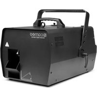
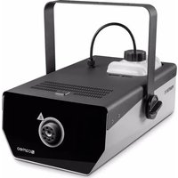
Professional fog machine. DMX-512 control. 3-pin and 5-pin XLR connector. Overheat protection. FLYKIT optionally available. Operating voltage: 230V AC / 50-60Hz Power consumption: 1800W.
CONNECTIONS, CONTROL AND DISPLAY ELEMENTS

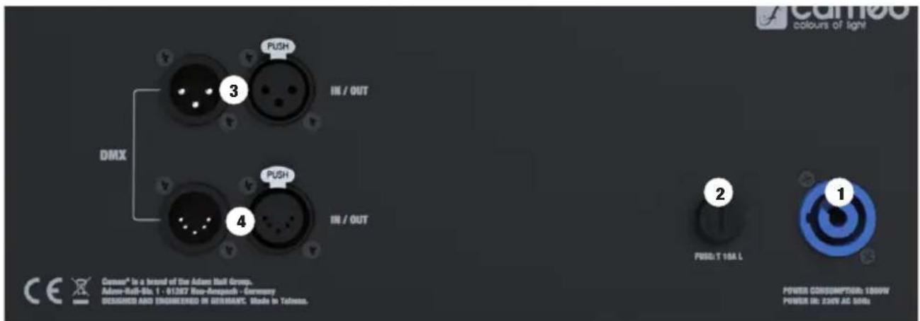
1 POWER IN
Power Twist power outlet to provide power to the device, a suitable power cable is included in delivery.
2 FUSE
Fuse holder for 5 × 20 mm micro fuses. IMPORTANT INFO: Replace the fuse only with a fuse of the same type and values (see inscription on housing). If the fuse trips repeatedly, please contact an authorized service center.
③ DMX IN / OUT 3-PIN XLR
Male 3-pin connector to connect a DMX controller and a female 3-pin XLR connector to transmit the DMX control signal.
4 DMX IN / OUT 5-PIN XLR
Male 5-pin connector to connect a DMX controller and a female 5-pin XLR connector to transmit the DMX control signal.
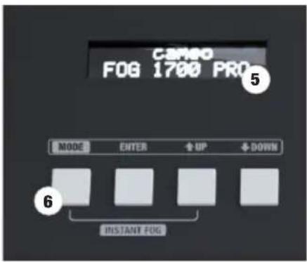
5 LC DISPLAY
The 2-line LC display with background illumination shows the currently active operating mode (main display), the menu options in the options menu, and the numerical values or operating status for certain menu options. If there is no control signal at the DMX input, the numbers will flash on the display; they will stop flashing as soon as a control signal is present (DMX and Slave mode).
6 CONTROL KEYS
MODE: Press MODE to access the options menu. Similarly, pressing MODE will take you one level higher in the menu structure to the main display (press several times where necessary) when in the options menu and submenus.
ENTER: In the options menu, press ENTER to access the menu level where you can change values. You can also confirm value adjustments by pressing ENTER.
UP and DOWN: Select the individual menu items in the options menu (device settings, operating mode, etc.) and submenus, and change the value of a menu item, e.g. the DMX address.
INSTANT FOG: Press and hold the MODE and UP buttons at the same time in order to manually start the maximum fog discharge. To stop the fog discharge, release the buttons.
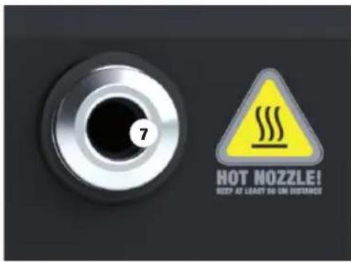
7 FOG OUTPUT NOZZLE
The fog output nozzle is located on the front side of the fog machine. Caution, hot! When setting up the fog machine, follow the information under "CAUTION! IMPORTANT INFORMATION ON FOG MACHINES!" in the safety instructions.
CANISTER COMPARTMENT AND SPECIAL COVER FOR CANISTER

8 CANISTER COMPARTMENT
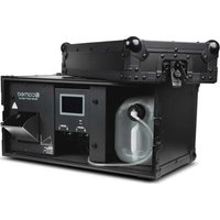
Canister compartment for a 5l canister of Cameo fog fluid.
⑨ SEALING CAP FOR FLUID HOSE
Remove the sealing cap from the fluid hose in order to connect the hose to the special canister cover. When the fluid hose is not connected to the fluid hose, close it using the sealing cap.
10 FLUID HOSE
Fluid hose with hose nozzle and black sealing ring. Connect the fluid hose to the canister cover by inserting the hose nozzle into the quick connector until the locking mechanism engages. Make sure that the connection is tight. To release the fluid hose, press the spring-loaded release button (no. 11).
11 RELEASE BUTTON
To release the fluid hose from the special cover, press the spring-loaded release button (no. 11) of the quick connector.
⑫ VENTILATION VALVE
Ventilation valve with corresponding hose.
13 INTAKE HOSE
Intake hose with sinter filter.
Before replacing the canister or refilling fog fluid, disconnect the fog machine from the power supply (remove the power plug).
The special canister cover with ventilation valve and intake hose, suitable for 5l Cameo fog fluid canisters, included in delivery (canister not included). Place a full Cameo fog fluid canister upright in front of the fog machine and unscrew the canister lid. Now take the included special cover and insert the hose of the ventilation valve and the intake hose (no. 12 and 13) into the canister and screw the special cover tight to the canister. The sinter filter on the intake hose ensures that contaminant particles do not get into the system and that the hose end is always at the lowest point of the canister. Now set the canister into the canister compartment and connect the fluid hose of the fog machine on the special cover (see no. 10). To remove a fluid canister, please first loosen the fluid hose from the special cover.
OPERATION
NOTES
- After connecting to the power supply, "Welcome to Cameo", the model designation, and the software version will display one after the other. At the same time, the vaporizer will heat up (approx. 7 minutes), during which "Heating ..." will be shown on the display; system settings can be applied as needed during this time.
- After the heating phase is complete, "Ready!" will display briefly and then the operating mode previously selected will activate.
- When the heat-up phase is complete, fog will only release when the main screen shows one of the available operating modes (DMX, Stand Alone, Timer, Slave mode); the fog discharge halts automatically as soon as one of the menu options is chosen from the options menu or submenu in order to prevent injury from the discharged fog.
- Do not operate the fog machine without fog fluid! When the canister runs out during use, the fluid pump is switched off automatically for protection purposes, "Low Liquid Protection" is shown on the display, and the canister light simultaneously starts to flash. Disconnect the fog machine from the power supply before changing the canister or filling it with fog fluid. Then, use the "Instant Fog" function (maximum fog discharge) in order to completely fill the fluid hose with fog fluid again, in order to prevent the automatic pump switch-off from reactivating.
- In order to remove fluid residue in the vaporizer system of your fog machine and thus ensure a long service life, clean the vaporizer system regularly (approx. every 60 operating hours). To do so, use the special Cameo cleaning fluid for fog machines and follow the instruction on the bottle label.
SETTING THE DMX START ADDRESS (DMX Address)
You can access the options menu by pressing MODE. Using the UP and DOWN control keys, now select the "DMX Address" menu option and confirm via ENTER. Use the UP and DOWN keys to set the desired DMX start address and confirm this entry via ENTER. The main screen now displays the operating mode and DMX start address and automatically activates the DMX operating mode.
Main display
DMX address
ENTER UP/DOWN
DMX address 001 - 5XX
ENTER
DMX-Mode DMX-Address: xxx
SETTING DMX MODE
You can access the options menu by pressing MODE. Using the UP and DOWN control keys, now select the "DMX Mode" menu option and confirm by selecting ENTER. Use the UP and DOWN keys to select the desired DMX mode (3CH mode / 1CH mode) and then press ENTER to confirm your selection. The main screen now displays the mode and DMX start address and automatically activates the DMX mode. You can find detailed DMX tables for both DMX modes in these instructions under "DMX CONTROL".
Main display
DMX Mode
ENTER UP/DOWN
3CH Mode 1CH Mode
ENTER
DMX-Mode DMX-Address: xxx
STAND ALONE MODE (Stand Alone)
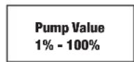
Stand Alone mode makes it possible to manually configure the fog discharge of the machine using values of 1% to 100%. You can access the options menu by pressing MODE. Using the UP and DOWN control keys, now select the "Stand Alone" menu option and confirm by pressing ENTER 2x. Using the UP and DOWN control keys, now set the desired value and confirm via ENTER.
Main display
Stand Alone
ENTER
Stand Alone Pump
ENTER UP/DOWN
Pump Value 1% - 100%
ENTER
Stand Alone mode Pump Value: x%
TIMER MODE (Timer)
Timer mode makes it possible to manually configure the fog discharge of the device using values of 1% to 100%, as well as the output duration and the interval at which the discharge is to begin. You can access the options menu by pressing MODE. Using the UP and DOWN control keys, now select the "Timer" menu option and confirm via ENTER. Now select between "Timer Pump" (output quantity), "Timer Duration" (output duration), and "Timer Interval" (output interval) via UP and DOWN, confirm with ENTER, and set the desired value using UP and DOWN respectively. Confirm each entry via ENTER.
Main display
Timer
ENTER UP/DOWN
Timer Pump
/
Timer Duration
/
Timer Interval
Timer mode Duration/Interval xSec
ENTER - UP/DOWN
ENTER - UP/DOWN
ENTER - UP/DOWN
ENTER

ENTER

ENTER
SLAVE MODE (Slave)
You can access the options menu by pressing MODE. Using the UP and DOWN control keys, now select the "Slave" menu option and confirm via ENTER. Connect the slave and master unit (same model, same software version) using a DMX cable (Master DMX OUT - Slave DMX IN), and activate Stand Alone or Timer mode on the master unit. The slave unit will now follow the master unit.
Main display
Slave
ENTER
Slave mode
DEVICE SETTINGS (Settings)
You can access the options menu by pressing MODE. Using the UP and DOWN control keys, now select the "Settings" menu option (note arrow) and confirm via ENTER.
Settings
ENTER
This will take you to the submenu for setting the following submenu options (select via UP and DOWN, confirm via ENTER, change status via UP and DOWN, confirm via ENTER):
| Settings | ||||
| Display Settings | = | Configures the display and control key illumination and canister illumination | Display and LEDs on | Display, control key, andcanister illumination permanently on |
| Display off | Display off after 30 seconds of inactivity, control key and canister illumination on | |||
| Display and LEDs Dark Mode | Display, control key, andcanister illumination off after 30 seconds of inactivity | |||
| Settings DMX Fail | = | Operating status for DMX signal interruption | DMX Fail Hold | last command will be held |
| DMX Fail Stop fog output | Stops fog output | |||
| Settings Auto Lock Unit | = | Automatic locking Auto Lock Unit | off | Automatic locking deactivated |
| Auto Lock Unit 60sec | Auto Lock is activated after approx. 60 seconds of inactivity(release byholding UP and DOWN for approx. 10 seconds) | |||
SYSTEM INFORMATION (System Info)
You can access the options menu by pressing MODE. Using the UP and DOWN control keys, now select the "System Info" menu option and confirm via ENTER.
System Info
ENTER
This will take you to the submenu for displaying the device information. Use the UP and DOWN buttons again to select the desired parameter, then press ENTER to call up the information.
| System Info | |||
| Firmware = Displays the device firmware Software Version | Vx.xx | ||
| Operating Hours | = Operating time display of the fog machine in hours Operating Hours | Total: x | |
ADAPTER FOR 100MM HOSE
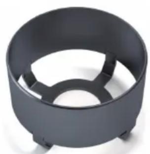
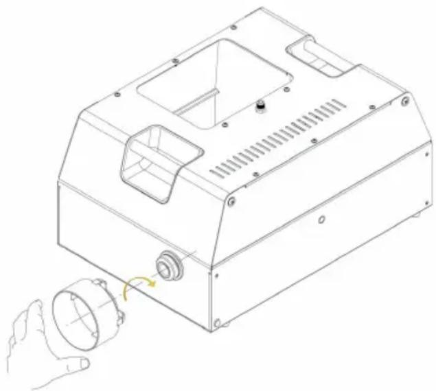
An adapter for a 100mm hose is included in delivery. The adapter can be screwed onto the fog output nozzle when needed. Disconnect the fog machine from the power supply (pull out the plug) and wait until the vaporizer of the fog machine has cooled completely cooled before mounting the adapter.
SETUP AND INSTALLATION
Place the fog machine in a suitable location on its preinstalled rubber feet. A crossbeam can be installed by means of a flybar that is included in the optionally available FLYKIT (CLIF1700PROFLYKIT) and is attached to the laterally inserted threads. The drip tray, which is also included with the FLYKIT, is attached to the front under the fog output nozzle. Ensure that the connections are tight and secure the spotlight to one of the carrying handles (A) using a suitable safety rope. The maximum permitted incline of the fog machine is 30°. During setup and installation, follow the information under "CAUTION! IMPORTANT INFORMATION ON FOG MACHINES!" in the safety instructions.

Important safety informationOverhead installation requires extensive experience, including the calculation of workload limits and installed equipment, and periodic safety checks of all installation materials and devices. If you are not qualified to do so, do not try to complete installation yourself; get the assistance of a professional company.
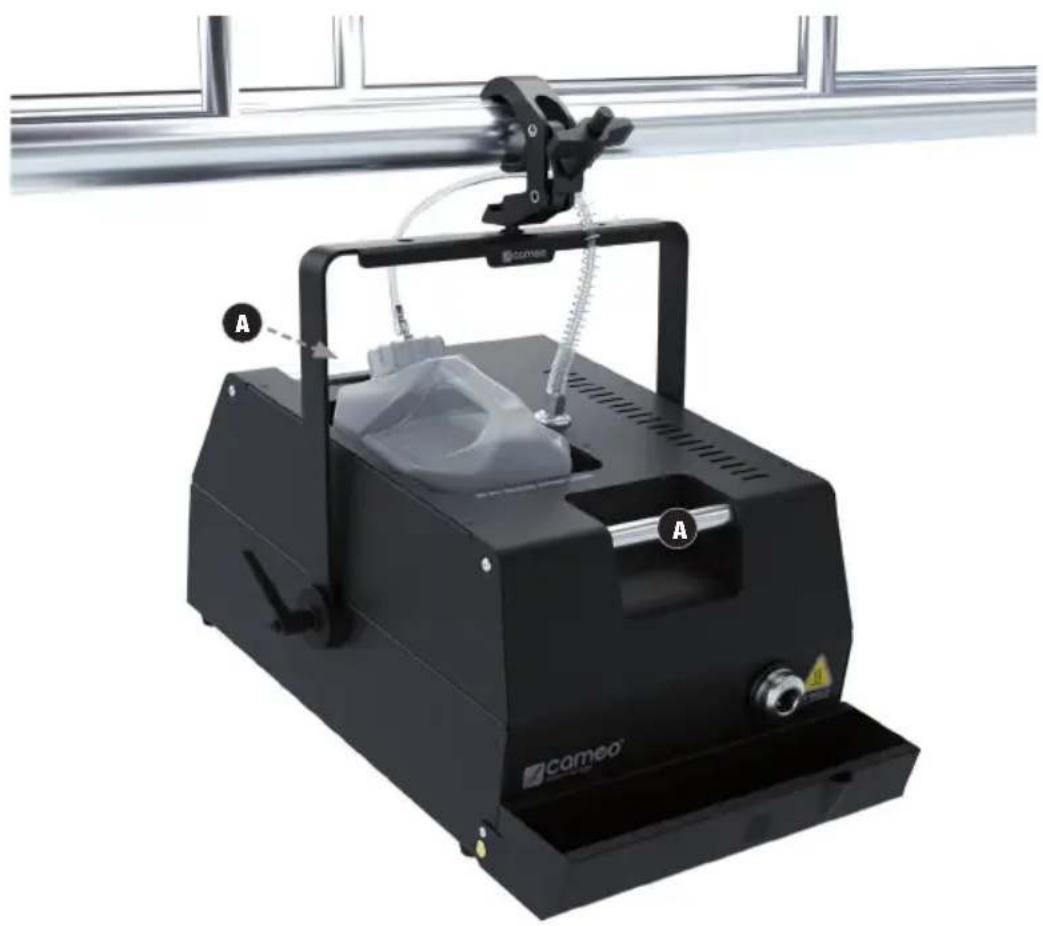
Transport strap, drip tray, and canister not included in delivery!
DMX TECHNOLOGY
DMX-512
DMX (Digital Multiplex) is the designation for a universal transmission protocol for communications between corresponding devices and controllers. A DMX controller sends DMX data to the connected DMX device(s). The DMX data is always transmitted as a serial data stream that is forwarded from one connected device to the next via the "DMX IN" and "DMX OUT" connectors (XLR plug-type connectors) that are found on every DMX-capable device, provided the maximum number of devices does not exceed 32 units. The last device in the chain needs to be equipped with a terminator (terminating resistor).

DMX CONNECTION
DMX is the common "language" via which a very wide range of types and models of equipment from various manufacturers can be connected with one another and controlled via a central controller, provided that all of the devices and the controller are DMX compatible. For optimum data transmission, it is necessary to keep the connecting cables between the individual devices as short as possible. The order in which the devices are integrated in the DMX network has no influence on the addresses. Thus the device with the DMX address 1 can be located at any position in the (serial) DMX chain: at the beginning, at the end or somewhere in the middle. If the DMX address 1 is assigned to a device, the controller "knows" that it should send all data allocated to address 1 to this device regardless of its position in the DMX network.
SERIAL CONNECTION OF MULTIPLE LIGHTS
- Connect the male XLR connector (3-pin or 5-pin) of the DMX cable to the DMX output (female XLR socket) of the first DMX device (e.g. DMX-Controller).
- Connect the female 3-pin XLR connector of the DMX cable connected to the first projector to the DMX input (male 3-pin socket) of the next DMX device. In the same way, connect the DMX output of this device to the DMX input of the next device and repeat until all devices have been connected. Please note that as a rule, DMX devices are connected in series and connections cannot be shared without active splitters. The maximum number of DMX devices in a DMX chain should not exceed 32 units.
The Adam Hall 3 STAR, 4 STAR, and 5 STAR product ranges include an extensive selection of suitable cables.
DMX CABLES
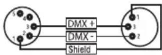
When fabricating your own cables, always observe the illustrations on this page. Never connect the shielding of the cable to the ground contact of the plug, and always make certain that the shielding does not come into contact with the housing of the XLR plug. If the shielding is connected to the ground, this can lead to short-circuiting and system malfunctions.
Pin Assignment
DMX cable with 3-pin XLR connectors: DMX cable with 5-pin XLR connectors (pin 4 and 5 are not used):
![graph LR A["1"] --> B["Shield"] C["3"] --> B D["2"] --> B B --> E["DMX +"] B --> F["DMX -"] E --> G["1"] F --> H["2"] G --> I["3"]](/content/2026/04/633126/images/033bfbe11c003a959121c845011e16cc4d56ed0a804e1f691e0692030f6194d2.jpg)

DMX TERMINATORS (TERMINATING RESISTORS)
To prevent system errors, the last device in a DMX chain needs to be equipped with a terminating resistor (120 ohm, 1/4 Watt).
3-pin XLR connector with a terminating resistor: K3DMXT3
5-pin XLR connector with a terminating resistor: K3DMXT5
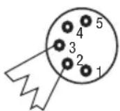
Pin Assignment
3-pin XLR connector: 5-pin XLR connector:

DMX ADAPTER
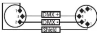
The combination of DMX devices with 3-pin connectors and DMX devices with 5-pin connectors in a DMX chain is possible with suitable adapters.
Pin Assignment
DMX Adapter 5-pin XLR male to 3-pin XLR female: K3DGF0020
Pins 4 and 5 are not used.
Pin Assignment
DMX Adapter 3-pin XLR male to 5-pin XLR female: K3DHM0020
Pins 4 and 5 are not used.


SPECIFICATIONS
Article number: CLIF1700PRO
| Product type: Fog machine | |
| Type: Fog generator per vaporization principle | |
| Heat-up time: approx. 7 minutes | |
| DMX input: 3-pin and 5-pin XLR, male | |
| DMX output: 3-pin and 5-pin XLR, female | |
| DMX mode: 3 channel, 1 channel | |
| DMX functions: Fog Quantity, Interval | |
| Stand Alone functions: Fog Quantity, Interval, Instant Fog | |
| Control: DMX512 | |
| Control elements: Mode, Enter, Up, Down | |
| Display elements: Illuminated 2-line LC display, canister illumination, button illumination | |
| Operating voltage: | 230V AC / 50-60Hz |
| Power consumption: | 1800W |
| Overheat protection: | Heating element with thermostat |
| Power supply connector: | Power Twist connector |
| Fuse: | T10AL (5x20mm) |
| Ambient temperature (running): | 5°C - 40°C |
| Relative humidity: | < 85%, non-condensing |
| Housing material: metal | |
| Housing color: | black |
| Dimensions (W x H x D): | 325 x 235 x 476 mm |
| Weight (without canister): | 14.9 kg |
| Additional information: | 4 rubber feet. Special canister cover with ventilation valve and intake hose included. Power cable and 100 mm hose adapter included. FLYKIT optionally available |
MANUFACTURER'S DECLARATIONS
MANUFACTURER'S WARRANTY & LIMITATIONS OF LIABILITY
You can find our current warranty conditions and limitations of liability at: https://cdn-shop.adamhall.com/media/pdf/MANUFACTURERS-DECLARATIONS_LD_SYSTEMS.pdf To request warranty service for a product, please contact Adam Hall GmbH, Adam-Hall-Str. 1, 61267 Neu Anspach / Email: Info@adamhall.com / +49 (0)6081 / 9419-0.

CORRECT DISPOSAL OF THIS PRODUCT
(valid in the European Union and other European countries with a differentiated waste collection system)
This symbol on the product, or on its documents indicates that the device may not be treated as household waste. This is to avoid environmental damage or personal injury due to uncontrolled waste disposal. Please dispose of this product separately from other waste and have it recycled to promote sustainable economic activity. Household users should contact either the retailer where they purchased this product, or their local government office, for details on where and how they can recycle this item in an environmentally friendly manner. Business users should contact their supplier and check the terms and conditions of the purchase contract. This product should not be mixed with other commercial waste for disposal.
FCC STATEMENT
This device complies with Part 15 of the FCC Rules. Operation is subject to the following two conditions:
(1) This device may not cause harmful interference, and
(2) This device must accept any interference received, including interference that may cause undesired operation
CE Compliance
Adam Hall GmbH states that this product meets the following guidelines (where applicable):
R&TTE (1999/5/EC) or RED (2014/53/EU) from June 2017
Low voltage directive (2014/35/EU)
EMV directive (2014/30/EU)
RoHS (2011/65/EU)
The complete declaration of conformity can be found at www.adamhall.com.
Furthermore, you may also direct your enquiry to info@adamhall.com.
DEUTSCH

1 POWER IN
Duration Time 1sec - 60sec
Interval Time 1sec - 60sec
ENTER
ENTER
ENTER

DMX-VERBINDUNG:

③ DMX IN / OUT XLR 3 BROCHES
4 DMX IN / OUT XLR 5 BROCHES
Duration Time 1sec - 60sec
Interval Time 1sec - 60sec
ENTER
ENTER
ENTER
MODE SLAVE (esclave)

INSTALLATION ET MONTAGE
PROTOCOLE DMX
(Valid in the European Union and other European countries with waste separation)

1 POWER IN
Duration Time 1sec - 60sec
Interval Time 1sec - 60sec
ENTER
ENTER
ENTER
MODO ESCLAVO (Slave)

CONEXIONADO DMX
1 POWER IN
7 DYSZA WYLOTOWA DYMU
Duration Time 1sec - 60sec
Interval Time 1sec - 60sec
ENTER
ENTER
ENTER
TRYB SLAVE (Slave)
USTAWIANIE I MONTAŻ
ZŁĄCZE DMX:

1 POWER IN
③ DMX IN / OUT 3 POLI XLR
Duration Time 1 sec. - 60 sec.
Interval Time 1 sec. - 60 sec.
ENTER
ENTER
ENTER

COLLEGAMENTO DMX:
- INSTANT FOG 1700 PRO
- CONTENTS / INHALTSVERZEICHNIS / CONTENU / CONTENIDO / TREŚĆ / CONTENUTO
- ENGLISH
- DEUTSCH
- SAFETY INFORMATION
- FOR DEVICES CONNECTED TO A POWER SUPPLY
- ATTENTION
- CAUTION! IMPORTANT INFORMATION ON FOG MACHINES
- INTRODUCTION
- PROFESSIONAL FOG MACHINE
- CONTROL FUNCTIONS
- PROPERTIES
- CONNECTIONS, CONTROL AND DISPLAY ELEMENTS
- 1 POWER IN
- 2 FUSE
- ③ DMX IN / OUT 3-PIN XLR
- 4 DMX IN / OUT 5-PIN XLR
- 5 LC DISPLAY
- 6 CONTROL KEYS
- 7 FOG OUTPUT NOZZLE
- 8 CANISTER COMPARTMENT
- ⑨ SEALING CAP FOR FLUID HOSE
- 10 FLUID HOSE
- 11 RELEASE BUTTON
- ⑫ VENTILATION VALVE
- 13 INTAKE HOSE
- OPERATION
- NOTES
- SETTING THE DMX START ADDRESS (DMX ADDRESS)
- SETTING DMX MODE
- STAND ALONE MODE (STAND ALONE)
- TIMER MODE (TIMER)
- SLAVE MODE (SLAVE)
- DEVICE SETTINGS (SETTINGS)
- SYSTEM INFORMATION (SYSTEM INFO)
- SYSTEM INFO
- ADAPTER FOR 100MM HOSE
- SETUP AND INSTALLATION
- DMX TECHNOLOGY
- DMX-512
- DMX CONNECTION
- SERIAL CONNECTION OF MULTIPLE LIGHTS
- DMX CABLES
- PIN ASSIGNMENT
- DMX TERMINATORS (TERMINATING RESISTORS)
- DMX ADAPTER
- SPECIFICATIONS
- MANUFACTURER'S DECLARATIONS
- MANUFACTURER'S WARRANTY & LIMITATIONS OF LIABILITY
- CORRECT DISPOSAL OF THIS PRODUCT
- FCC STATEMENT
- CE COMPLIANCE
- DMX-VERBINDUNG
- ③ DMX IN / OUT XLR 3 BROCHES
- 4 DMX IN / OUT XLR 5 BROCHES
- MODE SLAVE (ESCLAVE)
- INSTALLATION ET MONTAGE
- PROTOCOLE DMX
- MODO ESCLAVO (SLAVE)
- CONEXIONADO DMX
- 7 DYSZA WYLOTOWA DYMU
- TRYB SLAVE (SLAVE)
- USTAWIANIE I MONTAŻ
- ZŁĄCZE DMX
- ③ DMX IN / OUT 3 POLI XLR
- COLLEGAMENTO DMX
Brand : Cameo
Model : Instant Fog 1700 Pro
Category : Effect machine