
TG551A - Smoke detector HAGER - Free user manual and instructions
Find the device manual for free TG551A HAGER in PDF.
| Product Type | Smoke and heat detector, radio interconnectable, 10-year lithium battery |
| Dimensions (Diameter x Height) | 116 mm x 49 mm |
| Weight | 255 g |
| Power Supply | Sealed non-replaceable 2 x 3 V lithium battery, 10-year lifespan |
| Detection Type | Optical smoke and thermal (rate of temperature rise or threshold 54-70 °C) |
| Radio Interconnection | Up to 40 detectors, frequency 868-870 MHz, range adapted to dwellings |
| Acoustic Alarm | 85 dB(A) at 3 m in detection, 75 dB(A) at 1 m in test/fault |
| Visual Signaling | Red LED (alarm/programming), yellow LED (operation), white LED (emergency halo) |
| Maintenance and Cleaning | Vacuum the slots at least once a year or when a dirty head fault occurs |
| Safety | IP22 rating, temperature -10 °C to +65 °C, compliant with EN 14604:2005+AC:2008, CE marking |
| Spare Parts and Repairability | No spare parts; replace the entire detector and base. Battery non-replaceable. |
| General Information | Indoor use, coverage 50 m², 24-month warranty, 10-year lifespan, do not paint, stop by infrared remote control |
Frequently Asked Questions - TG551A HAGER
User questions about TG551A HAGER
0 question about this device. Answer the ones you know or ask your own.
Ask a new question about this device
Download the instructions for your Smoke detector in PDF format for free! Find your manual TG551A - HAGER and take your electronic device back in hand. On this page are published all the documents necessary for the use of your device. TG551A by HAGER.
USER MANUAL TG551A HAGER
natural_image
Technical line drawing of a cylindrical mechanical component with a central circular hole and four side slots (no text or symbols)GB installation manual - p. 90 Smoke and heat detector, interconnectable radio, lithium battery 10 years
Sommaire
B
natural_image
Technical diagram of a mechanical component with internal parts and a magnified inset showing a tool interacting with it (no text or symbols present)natural_image
Illustration of a mechanical component being held in hands, showing top view and bottom view with no text or symbols.
natural_image
Technical line drawing of a mechanical component with circular cross-section and internal features (no text or symbols)natural_image
Diagram showing a sun icon interacting with a circular object, no text or symbols presentnatural_image
Simple line drawing of a cylindrical object with internal features and two protrusions (no text or symbols)
OU

natural_image
Line drawing of a human hand making a gesture (no text or symbols)natural_image
Technical line drawing of a cylindrical component with internal channels and a separate patterned schematic (no text or symbols)natural_image
Simple line drawing of a cylindrical object with internal features and two side slots (no text or symbols)
natural_image
Simple line drawing of a cylindrical object with concentric rings and two small protrusions (no text or symbols)
OU

natural_image
Line drawing of a human hand with index finger extended (no text or symbols)natural_image
Pure technical diagram of a circular mechanical component with no text, numbers, or symbolsnatural_image
Technical line drawing of a cylindrical mechanical component with internal features and a diagonal line (no text or symbols)natural_image
Architectural floor plan of a single house showing internal compartments and fixtures (no text or labels)
Protezione minima:
natural_image
Technical diagram of a mechanical component with internal parts and a magnified inset showing a tool (no text or symbols)natural_image
Illustration of a mechanical component being held in hands, showing top-down view with an arrow indicating upward motion (no text or symbols present)
natural_image
Technical line drawing of a mechanical component with circular cross-section and side view (no text or symbols)natural_image
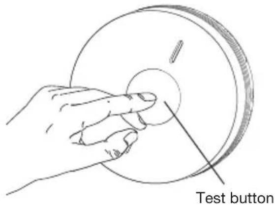
Hand holding a circular mechanical component with a pointer, no text or symbols visiblePulsante test

natural_image
Diagram showing a sun icon interacting with a circular object, no text or symbols presentnatural_image
Simple line drawing of a cylindrical object with internal features and two protrusions (no text or symbols)
OU
natural_image
Line drawing of a human hand making a gesture (no text or symbols)natural_image
Diagram of a cylindrical object with internal channels and a separate wavy line pattern (no text or symbols)Rivelatori interconnessi

natural_image
Simple line drawing of a cylindrical object with a central hole and two side holes (no text or symbols)
natural_image
Simple line drawing of a cylindrical object with a central hole and two side holes (no text or symbols)
OU
natural_image
Line drawing of a human hand with index finger extended (no text or symbols)Netzwerk
natural_image
Technical diagram of a mechanical component with cross-sectional view and magnified detail showing tool path (no text or symbols)natural_image
Illustration of a hand holding a container with internal components and an upward arrow indicating motion (no text or symbols)
natural_image
Technical line drawing of a mechanical component with circular cross-section and internal features (no text or symbols)rote LED /
natural_image
Diagram showing a sun icon interacting with a circular object, no text or symbols presentnatural_image
Simple line drawing of a cylindrical mechanical component with concentric layers and central hole (no text or symbols)
oder

natural_image
Line drawing of a human hand making a gesture (no text or symbols)natural_image
Technical line drawing of a cylindrical component with internal channels and a separate patterned schematic (no text or symbols)natural_image
Simple line drawing of a cylindrical object with internal grooves and two protrusions (no text or symbols)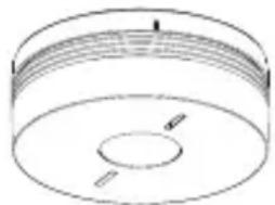
natural_image
Simple line drawing of a cylindrical object with internal features and two side slots (no text or symbols)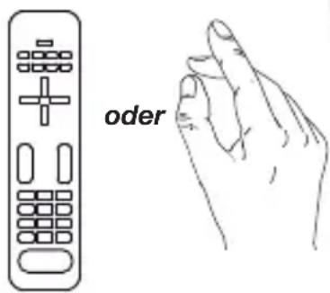

natural_image
Technical diagram of a mechanical component with internal parts and a magnified inset showing tool path (no text or symbols)natural_image
Illustration of a mechanical component being held in a container, showing top view and side view (no text or symbols)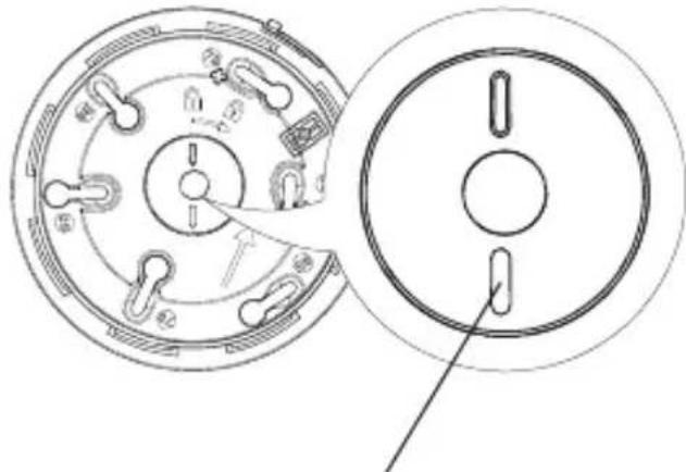
natural_image
Technical line drawing of a mechanical component with circular cross-section and side view (no text or symbols)Rood lampje / Geel lampje
natural_image
Diagram showing a sun icon interacting with a circular object, no text or symbols presentnatural_image
Simple line drawing of a cylindrical mechanical component with concentric layers and central hole (no text or symbols)
OF

natural_image
Line drawing of a human hand making a gesture (no text or symbols)natural_image
Two identical cylindrical mechanical components with internal grooves and mounting holes (no text or symbols)
OF

natural_image
Line drawing of a human hand making a gesture (no text or symbols)2.1. Choosing the best place to install the detector 93
2.2. Installing the detector as a standalone device 95
2.3. Installing the detector associated with the TKP100A coviva controller...... 98
2.3. Installing the detector as part of a network 98
2.4. Installing the detector as a relay.... 101
2.5. Putting a detector back into its factory configuration 102
3. Testing the detector.... 103
4. Using the detector.... 104
4.1. Inhibiting the detector.... 104
4.2. Stopping the alarm in the event of non-dangerous detection 104
4.3. Fault indications.... 106
5. Maintenance.... 107
5.1. Cleaning the detection head 107
5.2. Replacing the detector 107
5.3. In case of work in the home 108
6. Warranty 108
7. Technical data 109
1. Introduction
1.1. How the detector works
The smoke detector is designed to protect the private areas of apartment buildings, residential properties and mobile homes.
Smoke detection is especially suitable for detecting slow-starting fires that can smoulder for many hours before catching alight.
Heat detection is activated when:
- the rate of elevation of the ambient temperature is abnormal,
- or the ambient temperature reaches a value between 54 and 70^
It can be: • used alone,
- included in a hager alarm system with TwinBand® control panel,
- interconnected in a wireless network with 40 detectors maximum.
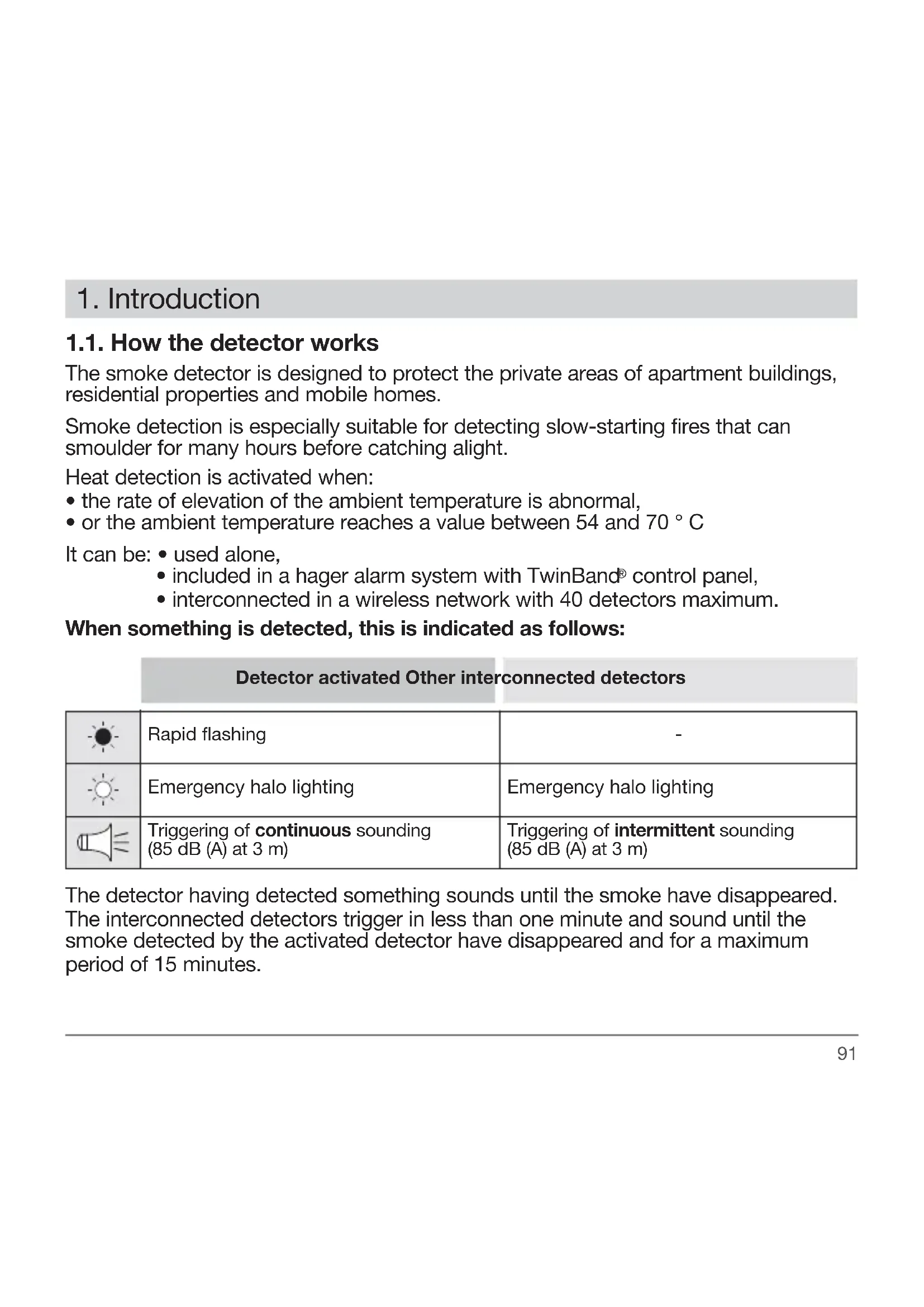
When something is detected, this is indicated as follows:
Detector activated Other interconnected detectors
 | Rapid flashing | - |
 | Emergency halo lighting | Emergency halo lighting |
 | Triggering ofcontinuous sounding(85 dB (A) at 3 m) | Triggering ofintermittentsounding(85 dB (A) at 3 m) |
The detector having detected something sounds until the smoke have disappeared. The interconnected detectors trigger in less than one minute and sound until the smoke detected by the activated detector have disappeared and for a maximum period of 15 minutes.

Subject to the smoke detector being properly serviced on a regular basis, it should be replaced according to the replacement date indicated on the back of the product or when its battery runs out.
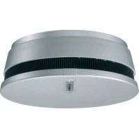
1.2. Description
Fixing base
natural_image
Technical line drawing of a circular mechanical component with internal components and arrows indicating assembly (no text or symbols)LED alignment arrow (gives the alignment axis of the LEDs once the detector has been locked on to its base)

White LED (emergency halo lighting)
Red LED (alarm and programming) Yellow LED (operation)
2. Installation

the detector comes ready powered. Simply lock it on to its base (step 4. Chapter 2.2. Installing the detector as a standalone device) to put it in normal operating mode.
2.1. Choosing the best place to install the detector
The detector must be placed:
- in rooms where there is a fire hazard (living rooms with fireplace, children's bedrooms, occupied lofts or basements, etc.) (Fig. A),
- preferably in the centre of the ceiling,
- far away from fan vents likely to spread smoke,
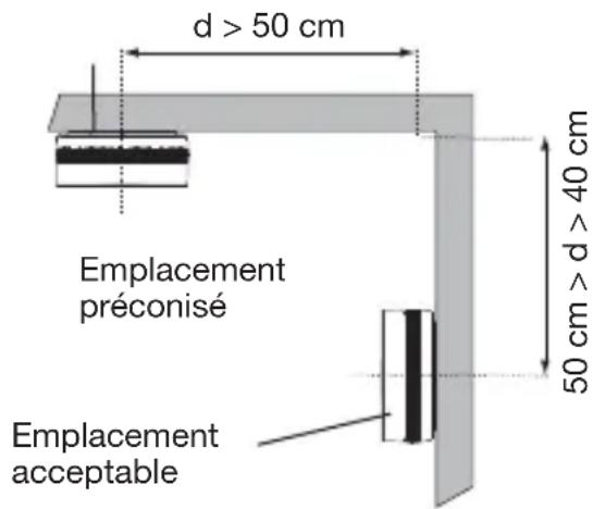
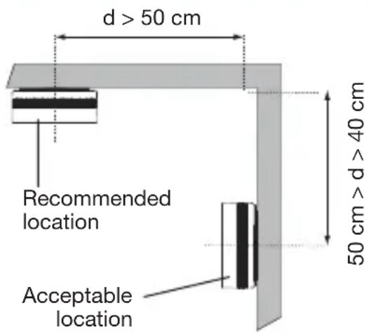
- more than 50 cm away from any obstacles (walls, partitions, beams, etc.) (Fig. B),
- at each end of corridors if they are longer than 10 m.
If the detector cannot be installed horizontally on the ceiling, fix it:
- at a distance of 40 to 50~cm from the ceiling (Fig. B),
- far away from any sources of electrical disturbance (electricity meter, metal cabinet, electronic ballast, etc.).
The detector must not be placed:
- close to an electronic ballast, low voltage transformer, energy saving light bulbs, fluorescent tubes, etc. (minimum distance: 50 cm),
- in excessively dusty rooms,
- in a room where the temperature might drop below -10^ or rise above +65^ , which would prevent the detector from operating properly,
- at least 1 m away from heating, cooling or air circulation vents likely to disseminate smoke or heat,
- at least 6 m away from a fireplace or wood burning stove where the smoke from combustion might trigger an unnecessary alarm,
-
in an area where cooking fumes and water vapour might cause unwanted triggering,
-
in a room where there might be condensation or damp (do not use in bathrooms, laundries, etc.)
- at the centre of a pointed ceiling (A-shaped), as the air pocket located here can prevent smoke from reaching the detector (Fig. C),
- directly on to a metal wall: use a non-magnetic spacer (wooden or plastic).
A.
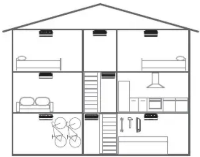

Minimum protection: a detector in a corridor or stairwell at every level and in every bedroom.

Optimum protection: minimum detection extended with the addition of a detector in each living area or basement.
B.
C.

2.2. Installing the detector as a standalone device
Use the LED alignment arrow on the base in order to position the detector in the best possible manner (see Description).
1 Fix the base keeping in mind the precautions outlined in the chapter entitled Choosing the best place to install the detector. The detector can be fixed in 2 ways:
Fixing the detector on a flush-mounting box
- For ∅ 60 mm boxes, use fixing holes marked 60.
- For ∅ 78 mm boxes, use fixing holes marked 78.
- For ∅ 85 mm boxes, use fixing holes marked 85.
• Fix the base using suitable screws.
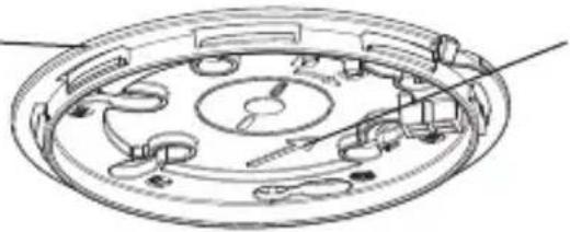
Fixing the detector on a surface
- Place the base in the planned location and mark the position of the 2 fixing holes with a pencil.
- Drill the holes using the right-sized diameter drill bit.
- Fix the base in place using suitable wall plugs and screws.
2 Optional locking of the detector on themounting base.
Optional locking is designed to prevent unauthorized dismounting of the detector. Using cutting pliers, cut out the locking slot.

Opening will now be possible only by means of a flat blade screwdriver.

natural_image
Technical diagram of a mechanical component with internal gear and assembly, showing two circular views of the main body (no text or symbols present)3 Line the marker up with the LEDs in order to position the detector on its base.
natural_image
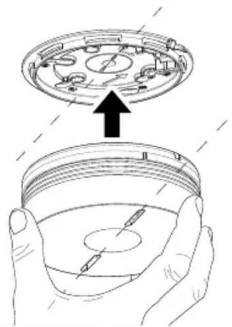
Illustration of a mechanical component being held in hands, showing top view and side view (no text or symbols)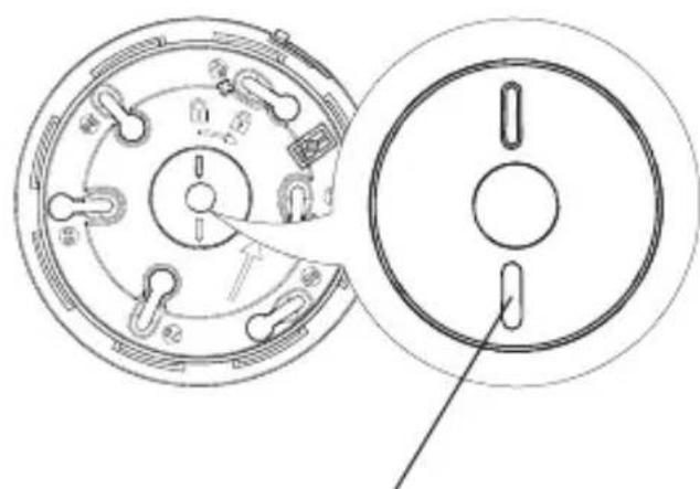
natural_image
Technical line drawing of a mechanical component with circular cross-section and side view (no text or symbols)Red LED/yellow LED
4 Turn the detector clockwise until it is completely locked. The yellow indication LED flashes for 5 s and then once every 10 s to indicate the detector is operating normally.

5 Proceed to chapter 3. Testing the detector.
2.3. Installing the detector associated with the TKP100A coviva controller
All detectors must be learned and within range radio of the coviva controller.
- Tap the application home page coviva on the blue "+" button on the "add page a detector" and select "Add one peripheral".
- Press "Go On", and press key held down on the CFG2 key until the application displays a message from confirmation.
- Continue with chapter 3. Testing the detector.

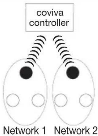
Principle of networking with the coviva controller
Radio networking of all detectors. All detectors must be learned and within range of radio of the coviva controller.
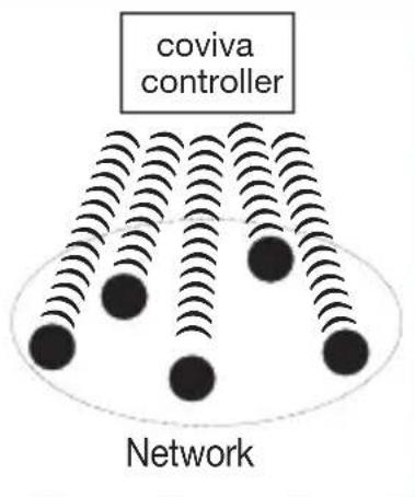
Radio relay with different models.
flowchart
graph TD
    A["coviva controller"] --> B["Network 1"]
    A --> C["Network 2"]
    B --> D["Device 1"]
    B --> E["Device 2"]
    C --> F["Device 1"]
    C --> G["Device 2"]
● Smoke detector (ex.: TG551A)
○ Network detector (ex.: TG550A)
2.4. Installing the detector as part of a network
It is possible to interconnect up to 40 detectors so that all the detectors in the home as well as the alarm system can be triggered together.
The smoke detector can be connected with TG550A smoke detectors and/or TG551A heat detectors.

The responses to detection are described in chapter 1.1. How the detector works.
To connect the detectors in a network:
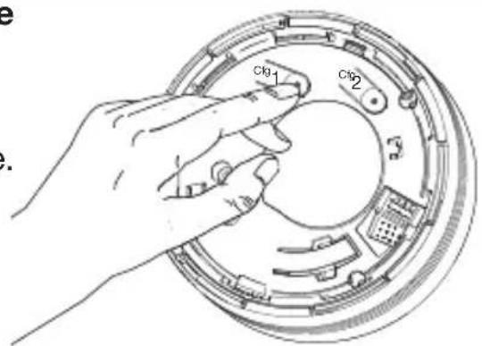
1 Put all the detectors to be networked in recognition programming mode by pressing 2 times on the Cfg1 key.

The red LED flashes.

2 Press the test button on one of the detectors until the red LED on all the other detectors lights up steadily. Release the button, the red LED of this detector flashes.
natural_image
Diagram showing a sun icon interacting with a circular object, no text or symbols present3 Lightly press on the Cfg1 key on all of the detectors to exit recognition programming mode.
Without press on the Cfg1 key the detectors outside the programming mode after one minute. In this case, the networking of the detectors is taken into account.
4 Test the radio range.
A. Put all the detectors in test mode by pressing once on the Cfg1 button.
The red LED lights up for 5 sec and then flashes.
B. Press the test button on one of the detectors and the detector will test the radio range in permanent transmission mode. The red LED on all the other detectors lights up steadily.
C. Position the detectors in their planned locations without fixing them in place.
- If the radio range is satisfactory, the red LED remains steadily lit.
- If the radio range is not satisfactory, the red LED flashes.
D. Move the detectors located outside of the radio range or programme one detector as a relay (see 2.4. Installing the detector as a relay) then perform the test again.
E. To exit the test mode, press once on the Cfg1 button on all the detectors. The red LED goes out.
F. Perform the radio range test for all the detectors again to make sure they trigger, whatever the detector having activated the alarm.
5 Fix the detectors in place following steps 1 to 4 in chapter 2.2. Installing a detector as a standalone device.
Specific cases
Adding a detector to an existing network
- Put the detector to be added to the network in recognition programming mode by pressing 2 times on the Cfg1 key. The red LED flashes.
- Put one of detector that are already in the network in recognition programming mode by pressing 2 times on the Cfg1 key. The red LED flashes.
- Press the test key on a detector that is already in the network until the red LED on both detectors lights up steadily.
- Briefly press Cfg1 on one of the detectors to exit the programming mode.
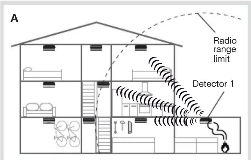
2.5. Installing the detector as a relay
If the radio range between all the detectors is insufficient, one of the detectors can be progra-med as a relay. This means that it will re-transmit alarms received to all the other detectors.
Examples:
A. If an alarm is activated on detector 1, only detector 2 and the control panel will be triggered.
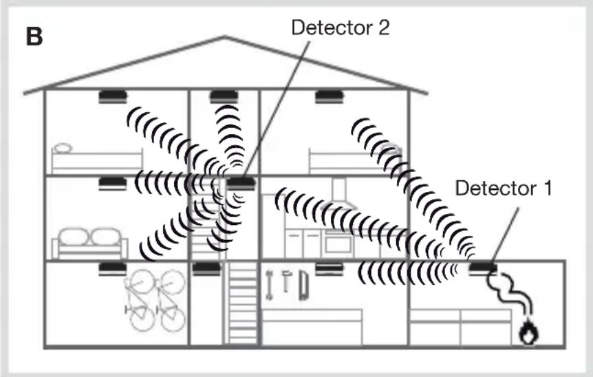
B. Detector 2 is programmed as a relay.
If an alarm is activated on detector 1, the detector retransmits the information on the whole installation.

- It is possible to programme just one “relay” detector per network.
- To be programmed as a relay, the detector must first have been programmed for recognition by the network.
To programme a detector as a relay:
- Press Cfg1. After 4 s, the red LED flashes. Keep holding the button down.
- After 10 s, the flashing speeds up or slows down:
- if the flashing speeds up, the relay function has been activated,
- if the flashing slows down, the relay function is still deactivated.
- Release the button and press briefly on Cfg1 to exit the programming mode.
2.6. Putting a detector back into its factory configuration
Upon the back into factory configuration, the interconnection between the detectors will be deleted.
- Press 2 times on the Cfg1 key. The red LED flashes.
- Keep holding on the Cfg1 key until the red LED light up steadily. Release the button.
- Briefly press Cfg1 to exit the programming mode.
3. Testing the detector

- The detectors must be installed before test.
- Before a smoke detector test, it is advisable to first let your neighbours know and take the necessary precautions to prevent hearing disorders.
- Never use a naked flame to test the detector.
- The test must be performed at least once a month and notably after a prolonged absence.
Press the detector test button until you hear the 2^nd beep and then release it.
Detector activated Other interconnected detectors
 | Rapid flashing | - |
 | Emergency halo lighting | Emergency halo lighting for 250 ms followed by a 1.75 sec. pause |
 | Sounding for 1 sec. (75 dB (A) at 1m) followed by a 1 sec. pause | Sounding for 250 ms (75 dB (A) at 1m) followed by a 1.75 sec. pause |
Press the test button again to stop the integrated sounding.
4. Using the detector
4.1. Inhibiting the detector
To prevent untimely triggering due to activities likely to generate smoke or dust (sweeping a dusty room, sweeping a chimney, etc.), the detector can be deactivated for roughly 15 min.
To do this, press one time on the test button. The detector beep, the red LED flash every 2 s.
Inhibited detector Other interconnected detectors
 | 1 flash every 2 seconds - |
After 15 min or after the manual test, the detector automatically becomes operational once more.

- During these 15 minutes, the detector will not be able to recognise smoke or generate an alarm.
- To exit inhibition mode more quickly, press the detector test button. The detector beep, the red LED stop flashing.
4.2. Stopping the alarm in the event of non-dangerous detection
To stop the alarm if it has detected harmless smoke:
- press the test button,
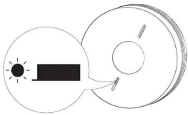
or - press one of the keys on an infrared remote control (remote control of a TV, DVD player, hi-fi system) and point the remote control towards the sounding detector. The detector will switch to inhibited mode (see chapter 4.1.) for 15 minutes.
Please note that the alarm can be stopped 20 s after the detector triggers the system.
If the detector is Installed as a standalone device:
- press the test button, or
- press 2 times one of the keys on the remote control pointed on the detector.
natural_image
Simple line drawing of a cylindrical object with internal features and two protrusions (no text or symbols)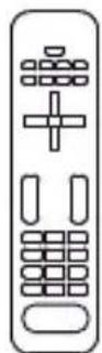
OR

natural_image
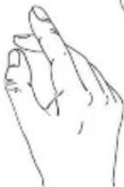
Line drawing of a human hand making a finger gesture (no text or symbols)If the detector is part of a network:
The detector(s) having been activated (red LED flashing) must be stopped to end network sounding.
Detector activated

natural_image
Simple line drawing of a cylindrical object with concentric layers and a central hole (no text or symbols)
natural_image
Abstract pattern of repeating wavy lines with no text or symbolsInterconnected detectors
natural_image
Pure technical line drawing of a cylindrical component with internal features (no text or symbols)
natural_image
Simple line drawing of a cylindrical object with a central hole and two side supports (no text or symbols)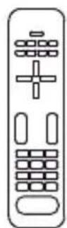
OR
natural_image
Line drawing of a human hand with index finger extended (no text or symbols)- The 1 ^st time one of the keys on the remote control or the detector test button is pressed: interconnected detectors stopped.
- The 2^nd time one of the remote control keys pointed on the detector or the test button of the detector having triggered the alarm is pressed: the detector having triggered the alarm is stopped.
4.3. Fault indications
In order not to wake you up, alarms resulting from mains supply problems or dirty sensors are shut down during the night. Any errors are corrected after daybreak within 10 minutes i.e. 12 hours after the event.
4.3.1. Power fault
| Detector at the source of the fault indication | Other interconnected detectors | |
 | 2 flashes every 5 sec. | 1 flash every 10 seconds |
 | 2 rapid beeps every 60 sec. 2 rapid beeps | every 60 sec. |
If the audible power fault indication occurs at an inconvenient time, it can be postponed for 12 hours over a maximum duration of 7 days by pressing the test button until you hear the first beep.
When the power fault occurs, the detector continues to operate perfectly for 30 days. It is advisable to replace the detector as soon as possible.
If the detector is associated with a control panel, the panel provides vocal notification following a system command: "Beep, power fault, detector n^ X ".
4.3.2. Detection head faulty or dirty
| Detector at the source of the fault indication | Other interconnected detectors | |
 | 8 flashes every 8 sec. | 1 flash every 10 seconds |
 | 8 rapid beeps every 60 sec. 8 rapid beeps | every 60 sec. |
If the audible detection head fault indication occurs at an inconvenient time, it can be postponed for 12 hours over a maximum duration of 7 days by pressing the test button until you hear the first beep.
You have these 7 days to clean the detector.
- If sounding continues after a postponement attempt, this means that the detection head is not working. Replace the detector.
- If the detection head fault indication occurs at night, this means that it is not working. Replace the detector.
- If the detection head indication does not stop after cleaning, replace the detector.
5. Maintenance
5.1. Cleaning the detection head
It is essential to keep the detector clean. The slots in the detection head must be vacuumed at least once a year or every time the detector indicates that its detection head is dirty (see Fault indications).
5.2. Replacing the detector

When you replace the detector, you must also replace its mounting base.
1 If the detector is replaced because of a battery or detection head fault, press on the test button until it beeps to clear the fault.
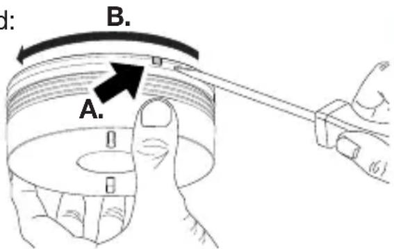
2
- If detector optional locking is not activated: turn the detector anti-clockwise to unlock it.
- If detector optional locking is activated:
A. insert a flat blade screwdriver into the slot,
B. turn the detector anti-clockwise to unlock it.
3
If the detector was part of a network, refer to 2.4. Installing a detector as part of a network.
4
- Position the new detector on its base by turning it clockwise until it is completely locked.
- Test the detector (see Testing the detector).
5.3. In case of work in the home
The detector must not be painted.
If work is to be carried out after the detector has been installed, cover it completely.
Do not forget to remove the protection when the work is finished.
6. Waranty
A warranty period of 24 months is offered on hager products, from date of manufacture, relating to any material or manufacturing defect. If any product is found to be defective it must be returned via the installer and supplier (wholesaler). The warranty is withdrawn if:
- after inspection by hager quality control dept the device is found to have been installed in a manner which is contrary to IEE wiring regulations and accepted practice within the industry at the time of installation.
- the procedure for the return of goods has not been followed.
Explanation of defect must be included when returning goods.
- Technical data
| Technical data Smoke detector | |
| Type of detection • optical smoke detector | • heat detector able to detect:- temperature rise speed- reaching of temperatures between 54 and 70°C |
| Average coverage 50 m | 2 |
| Use indoor | |
| Power | sealed, non-replaceable lithium battery 2 x 3 V with a 10-year battery life |
| Radio link Interlink: 868 - 870 MHz, 25 mW max, Duty cycle: 0,10%Rx: category 2 | |
| Indication • detector status | • faults |
| Integrated sounding upon detection 85 dB at 3 m | |
| 75 dB integrated sounding at 1 m • during testing• during fault indications | |
| Interconnection via radio 40 detectors | max. |
| Operating temperature -10°C to + 65°C | |
| Storage temperature -10°C to + 65°C | |
| Degree of protection IP22 | |
| Dimensions (D x H) 116 mm x 49 mm | |
| Weight | 255 g |
The label CE on this product certifies it conforms to the European directives and regulations that apply to it, and in particular that it conforms to the harmonised requirements of the standard EN 14604 (2005) + AC 2008 relating to the regulation RPC 305/2011 concerning construction products.

The label on this product only covers its function as a smoke detector.
The smoke detector TG551A 3 is in conformity with the requirements of the regulation (EU) N° 305/2011 and with all essential characteristics of the harmonized standard EN 14604 (2005) + AC 2008. The declaration of performance n° 0333-CPR-292073 of the product TG551A 3 can be downloaded on hager commercial internet site of the concerned country.
Hager Security SAS hereby declares that the radioelectric equipment, reference TG551A 3, complies with the requirements of the following 2014/53/EU RE-D directive.
The full text of the EU Declaration of Conformity is available at the address: www.hager.com.
The documentation provided with this product must be kept throughout the product's life time.

Disposing of waste electrical and electronic devices at the end of their service life (Applicable in European Union countries and other European countries with a waste collection system). This symbol on products or product packaging indicates that the product must not be thrown out with normal household waste. It must be taken to an appropriate collection point for recycling waste electrical and electronic equipment. By disposing of such products in the appropriate manner, you are helping to prevent any harmful effects they may have on the environment and human health. For further information about recycling this product, you should consult your local authorities, waste collection centre or the shop where you bought the product.
Recommendations
The user must not attempt to access the detector's internal parts, except areas described in this manual. If the user does access these parts, the product guarantee will be considered null and void and Hager shall not be held responsible for any problems. Touching the detector's internal parts and/or electronic components can damage the product. Furthermore, the detector is designed in such a way that these parts and components do not need to be accessed for operation or maintenance purposes.
Non-binding document, may be modified without prior notice.
:hager
Hager SAS
F-67212 OBERNAI CEDEX
Tél. +333 88 49 50 50


- Sommaire
- Testing the detector.... 103
- Using the detector.... 104
- Maintenance.... 107
- Warranty 108
- Technical data 109
- Introduction
- How the detector works
- Description
- Installation
- Choosing the best place to install the detector
- The detector must be placed:
- If the detector cannot be installed horizontally on the ceiling, fix it:
- The detector must not be placed:
- Installing the detector as a standalone device
- Fixing the detector on a flush-mounting box
- Fixing the detector on a surface
- Installing the detector associated with the TKP100A coviva controller
- Principle of networking with the coviva controller
- Installing the detector as part of a network
- Test the radio range.
- Specific cases
- Adding a detector to an existing network
- Installing the detector as a relay
- Examples:
- Putting a detector back into its factory configuration
- Testing the detector
- Using the detector
- Inhibiting the detector
- Stopping the alarm in the event of non-dangerous detection
- If the detector is Installed as a standalone device:
- If the detector is part of a network:
- Fault indications
- Power fault
- Detection head faulty or dirty
- Maintenance
- Cleaning the detection head
- Replacing the detector
- 2
- 3
- 4
- In case of work in the home
- The detector must not be painted.
- Waranty
- Hager Security SAS hereby declares that the radioelectric equipment, reference TG551A 3, complies with the requirements of the following 2014/53/EU RE-D directive.
- The documentation provided with this product must be kept throughout the product's life time.
- Recommendations
- :hager
Brand : HAGER
Model : TG551A
Category : Smoke detector