WXH202 - Smoke detector HAGER - Free user manual and instructions
Find the device manual for free WXH202 HAGER in PDF.


| Product type | Smoke detector (Kitchen Guardian) |
| Brand | Hager |
| Model | WXH202 |
| Category | Smoke detector |
| Power supply of detection unit | 2 AA/LR6 alkaline batteries (recommended type: Duracell Ultra Power MX1500) |
| Power supply of cut-off unit | 230 V single-phase or 400 V three-phase, via the cooker circuit |
| Battery type | AA/LR6 alkaline |
| Battery life | 3 to 5 years |
| Sound level | 70 to 75 dB(A) at 1 m |
| Radio frequency | 2.4 GHz |
| Radio range | 10 to 100 m depending on building structure |
| Nominal voltage (three-phase) | 400 V |
| Nominal current (three-phase) | 3 x 16 A |
| Nominal voltage (single-phase) | 230 V |
| Nominal current (single-phase) | 1 x 25 A |
| Power consumption (cut-off unit) | 4 W |
| Operating temperature | +5 °C to +35 °C |
| Protection rating | IP20 |
| Dimensions of cut-off unit (L x W x H) | 239 x 113 x 42 mm |
| Main functions | Monitoring of temperature and cooker usage; triggering a pre-alarm in case of danger; automatic cut-off of cooker power after 15 s without confirmation; audible and visual alarm; adjustable child safety |
| Child safety | Automatic, can be activated/deactivated by long press (5 s) on button 1 |
| Water leak sensor | Optional, connectable to the cut-off unit (maximum 4 sensors) |
| Potential-free contacts | 2 AUX outputs (AUX1 and AUX2) for signal transmission (e.g., KNX bus) |
| Maintenance and cleaning | Wipe the detection unit periodically with a damp cloth and a mild cleaning product |
| Standards | IEC/EN 60730-1 type 1.B ; DIN EN 50615 |
Frequently Asked Questions - WXH202 HAGER
User questions about WXH202 HAGER
0 question about this device. Answer the ones you know or ask your own.
Ask a new question about this device
Download the instructions for your Smoke detector in PDF format for free! Find your manual WXH202 - HAGER and take your electronic device back in hand. On this page are published all the documents necessary for the use of your device. WXH202 by HAGER.
USER MANUAL WXH202 HAGER
natural_image
Technical line drawing of a rectangular electronic component with mounting flanges and internal compartments (no text or symbols)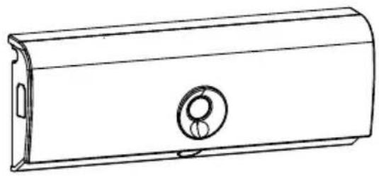
natural_image
Line drawing of a cylindrical mechanical housing with a circular vent and side port (no text or symbols)WXH20xWXH21x
Cookguard 3phase Cookguard 1phase
„Hager cookguard with Safera technology inside“
Content
Operating and assembly instructions 21
1 Safety instructions....21
2 Design and layout of the device 22
3 Function....23
4 Operation....24
4.1 Setting alarm limit....24
4.2 Automatic child lock....25
4.3 Dangerous situations....25
4.4 Alarm confirmation by tapping the sensor unit (optional) 25
4.5 Water leakage sensor (optional).... 26
4.6 Potential-free contacts (optional)....26
5 Information for electricians 28
5.1 Installation and electrical connection....28
5.2 Commissioning and performing a functional test ....32
5.3 Manual commissioning/Device setting ....33
5.4 Changing colour strips of the sensor unit 35
6 Appendix....36
6.1 Technical data 36
6.2 Troubleshooting....36
6.3 Accessories 37
Cookguard 1phase
WXH21x
Cookguard 3phase
WXH20x
Operating and assembly instructions
This document is only valid for devices with manufacturing dates after 09/2019
1 Safety instructions
Electrical equipment may only be installed and assembled by a qualified electrician. Always follow the relevant accident prevention regulations.
Failure to comply with these installation instructions may result in damage to the device, fire or other hazards.
Hazard due to electric shock. Before working on the device, disconnect all associated circuit breakers.
Hazard due to electric shock. The device is not suited for safe disconnection of the mains supply. Even when the device is switched off, the load is not galvanically separated from the mains supply.
The device is only suitable for use in private households and not for use in commercial kitchens or for cookers/hobs intended for commercial kitchens.
The device is only intended for mains-powered cookers/hobs.
The device is not intended for switching the cooker/hob on and off. The device only switches off the power supply in case of an alarm.
The device is not intended as a replacement for smoke detectors in residential buildings prescribed by law.
A functional test is to be carried out every three months on the device. (see chapter 5.2 Commissioning and performing a functional test).
Never intentionally cause dangerous situations on the cooker to test the device.
These instructions are an integral component of the product and must be retained by the end user.
2 Design and layout of the device
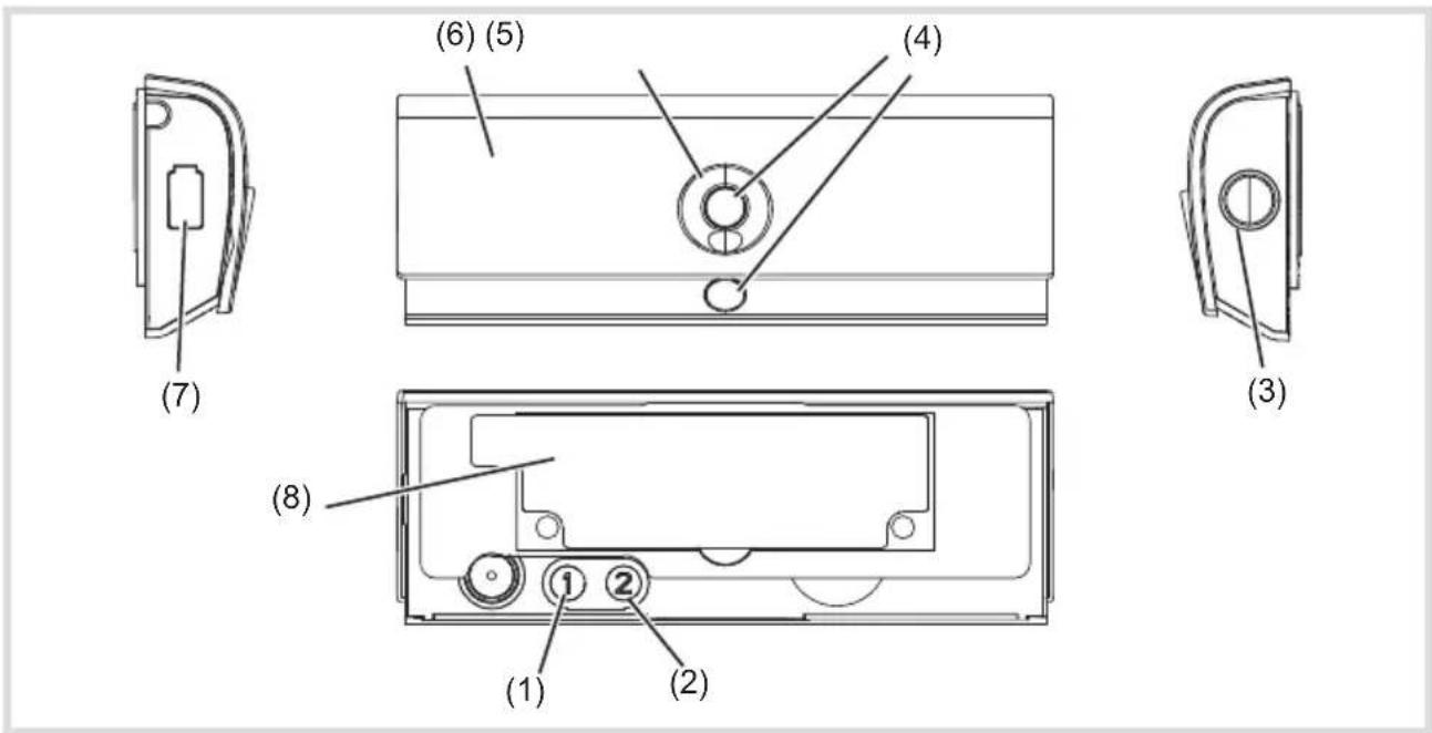
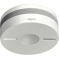
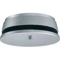
Figure 1: View of sensor unit
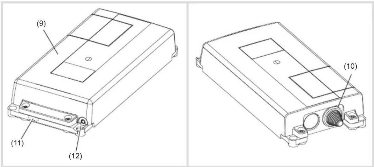
Figure 2: View of power control unit
(1) Operation button 1
(2) Operation button 2
(3) Operation button 3
(4) Sensors
(5) Status LED
(6) Front cover
(7) Battery status LED
(8) Mounting bracket with adhesive tape
(9) Power control unit
(10) Entry for connection cable cooker/hob
(11) Cut-out and cable entry for potential-free contacts (AUX)
(12) Connection socket for water leakage sensor
Scope of delivery
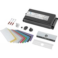
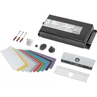
- Power control unit
- Sensor unit with mounting bracket
- white front cover for the sensor unit (pre-assembled)
- transparent front cover for the sensor unit
- Fitting material
- Cleaning pad
3 Function
Function notes
The cookguard is designed to draw attention to hazards as early as possible and to respond accordingly. According to the standard EN 50615 the device is able to distinguish between the normal use of a cooker/hob and a hazard. Nevertheless, during normal use of the cooker/hob attention hast to be paid to hazards as the device cannot detect all possible situations.
The sensor unit monitors the temperature increase and use of the cooker/hob. If a potential hazard is determined, a pre-alarm is triggered if necessary. If this is not acknowledged by the user, the power control unit switches off the power supply to the cooker/hob after 15 seconds. If the critical situation on the cooker has been remedied, the pre-alarm can be cancelled or the power supply to the cooker can be reactivated by pressing the operation button (3) or by tapping at any position on the sensor unit of the pre-alarm, if activated.
Correct use
- Ensuring the operational safety of electric cookers/hobs
-
Monitoring the cooking activities and switching off the cooker after identifying the hazard
-
10 Colour strips for inserting in the transparent front cover
- 2 Batteries for the sensor unit (AA/LR6)
- 2 connection terminals for N- and PE-conductor connection (3phase)
- 1 connection terminal PE-conductor connection (1phase)
- Operating and assembly instructions
- The device is only suitable for indoor areas
- Installation of the sensor unit on the wall or under the extractor hood
- Installation of the power control unit on the wall or on the floor
- The device is only intended for use in private households and is not to be used in conjunction with cookers and hobs as used in commercial kitchens.
- The device is to be used solely for monitoring electric cookers/hobs up to a maximum width of 90 cm.
Product characteristics
- Sensor unit with status display via LED (5)
- Display for low battery level via LED (7)
- Adjustable automatic child lock (deactivated by default).
- Connection for external water leakage sensor (optional, see Accessories)
- Connection for external signal generator via potential-free contact (optional, see Accessories)
4 Operation
Operating concept and display elements
In the event of an alarm, the device switches off the electric cooker, hob and informs the user
about the alarm situation via LEDs and acoustic signals. For this purpose, the device has one battery status LED (7), one status LED (5), three operating buttons (1 ... 3) and two sensors (4).
| Colour of status LED (5) Acoustic signal Function | ||
| green* - Cooker ready for use | ||
| flashing red yes Hazardous situation (pre-alarm) | ||
| slowly flashing red yes Power supply to cooker interrupted (alarm) | ||
| slowly flashing blue yes Water leakage alarm (optional) | ||
| white No Setting mode 1 | ||
| flashing purple-blue No Setting mode 2 | ||
| flashing yellow-green yes Setting mode 3 | ||
| flashing white | yes | Setting mode 4 (normal AUX mode) |
| flashing red Setting mode 4 (reversed AUX mode) | ||
* The Status LED (5) lights up in green shortly after pressing the operation button (3).
Table 1: Meaning of status LED
| Colour of battery status LED (7) | Acoustic signal | Function |
| flashing red | yes | Battery charge too low, battery life still approx. 2 weeks. |
| flashing red | - | Power supply to the cooker/hob is interrupted, LED flashes until the battery is completely empty. |
Table 2: Meaning of the battery status LED
To avoid false alarms, we recommend:
- wiping the sensor unit with a damp cloth and mild cleaning agent periodically
- leaving the sensor unit in its position and avoiding unintended movement
4.1 Setting alarm limit
The default setting is to be used for the initial setup. The alarm limit can be adjusted to the respective environment in the kitchen to ensure optimum functioning of the device. The alarm
limit can be adjusted if false alarms occur frequently (see Manual Settings). To do this, set the alarm limit two levels higher or lower (maximum) as recommended
4.2 Automatic child lock
The automatic child lock is deactivated by default.
Switching on child lock
- Keep the operation button (1) pressed for 5 seconds.
Two high acoustic signals (●●) sound and the status LED flashes green twice. Child lock is switched on.
The automatic child protection is activated about
10 ... 60 minutes after finishing cooking, in order to prevent the cooker/hob from being switched on accidentally.
4.3 Dangerous situations
If a potential hazard is determined, a pre-alarm is triggered if necessary. If this is not acknowledged by the user, the power control unit switches off the power supply to the cooker/hob after 15 seconds. If the critical situation on the cooker has been remedied, the pre-alarm can be cancelled or the power supply to the cooker can be reactivated by pressing the operation button (3) or by tapping on the sensor unit (see 4.4) of the pre-alarm.
Pre-alarm has tripped
■ Closely examine the situation on the cooker.
Press the operation button (3) if the situation on the cooker is OK.
Pre-alarm has been acknowledged. The cooker is not switched-off.
Switching off child lock
- Keep the operation button (1) pressed for 5 seconds.
A low acoustic signal (●) sounds and the status LED flashes red. Child protection is switched off.
Switching on cooker with activated child lock
■ Press operation button (3).
■ Switch on cooker/hob.
If the operation button (3) is not pressed first, the automatic child lock switches off the power supply of the cooker after 5 seconds.
Switching off the cooker
If the pre-alarm is not acknowledged within 15 seconds, the power supply of the cooker is interrupted.
If there is no danger or if the danger has been remedied, the power supply can be restored by pressing the operation button (3).
Avoid dangerous situations in the further course of cooking.
In the case of too frequent false alarms, manual commissioning must be carried out.
4.4 Alarm confirmation by tapping the sensor unit (optional)
The operation button (3) is pressed as standard to cancel the pre-alarm or to reconnect the power supply to the cooker. Alternatively, this can also be achieved simply by tapping the sensor unit.
Activating/deactivating the tap function:
- Hold the operation buttons 1 and 3 for approx. 5 seconds simultaneously until a signal tone sounds.
The Status LED (5) of the sensor unit flashes yellow 3x and then red 3x.
The tap function is activated.
OR:
The Status LED (5) of the sensor unit flashes yellow 3x and then blue 3x
The tap function is deactivated.
4.5 Water leakage sensor (optional)
The cookguard functions can optionally be extended with up to four water leakage sensors. If the sensors come into contact with water, a water leakage alarm is triggered (Table 1). The status LED flashes blue slowly accompanied by an acoustic signal.
Procedure with water leakage sensor:
- Press the operation button (3) to acknowledge the water leakage alarm.
■ The acoustic signal and flashing status LED (5) went out.
■ Switch off power supply.
■ Remove the cause of the water leakage.
- Clean and dry water leakage sensor(s) with a clean cloth.
■ Switch on power supply again and perform functional test.
If the water leakage sensor remains wet, it retriggers an alarm after 8 hours.
4.6 Potential-free contacts (optional)
The device has two potential-free contacts AUX1 and AUX2 (figure 6) e.g. that a KNX radio binary input can be connected to. In this way, for example, an alarm signal can be sent to the KNX bus. The alarm signal remains activated until the alarm (see Hazardous situation, water leakage) is acknowledged by pressing the button (3) on the sensor unit. The wiring of the potential-free contacts and their meaning is shown in table 3.
In the normal mode of the AUX outputs, the contact between In and Out is closed when ON and opened when OFF.
The AUX output signal can also be reversed. The reversed signal can, for example, be used to detect a cable breakage or if the power supply has been interrupted completely (see Chapter 5.1 "Connect potential-free contacts") In the inverted case, the contact between the In and Out terminals in the OFF state is closed and opened in the ON state.
If a KNX radio binary input is used, the usage of reversing AUX signals may lead to a reduction of the battery service life of the radio binary input.
The AUX outputs can be connected in four ways (Table 4). Option 1 is to be used for forwarding the alarm message.
| AUX1 AUX 2 System status | ||
| OFF OFF | No alarm message!Cooker switched off or no hazardous situation | |
| OFF On | Cooking activity is detected.This status is activated immediately after switching on the cooker. Depending on the intensity of the cooking, the signal is switched off 1 ... 30 min after finishing the cooking process. This delay time can be used to:- switch on e.g. an extractor hood or kitchen exhaust using the signal that is present.- perform an evaluation, how often cooking occurs, with the signal change from OFF ON . | |
| AUX1 AUX 2 System status | ||
| On OFF | Alarm!A hazardous situation is detected and the cookguard switches off the power supply in case of danger, timeout or overheating. The alarm state is also activated when the water leakage sensor has tripped; even though the power supply of the cooker/hob is not interrupted in this case. The alarm signal can only be deactivated by pressing the button (3) on the sensor unit.Water leakage sensor has tripped. The power supply to cooker is not interrupted. Leakage alarm is only switched off after pressing operation button (3). | |
| On On | Service!Fault on sensor, voltage interruption or empty battery detected and power supply to cooker is interrupted. The exact fault signal is displayed by pressing operation button (3) (see chapter 6.2 Troubleshooting). | |
Table 3: Output signals if external signal generator connected
| AUX1 / AUX 2 System status | |
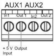 | Option 1:If a 1 signal is present on the AUX1 output, an alarm message is displayed. |
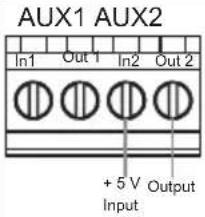 | Option 2:If a 1 signal is present on the AUX2 output, a normal cooking situation is displayed. |
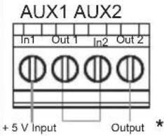 | Option 3:If a 1 signal is present on the AUX2 output and on the AUX2 output, a service technician must be called.*AUX1 and AUX2 are switched in series. The second potential carrying wire must be insulated according to the installation regulations. |
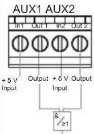 | Option 4:Both AUX outputs can be interconnected using an external logic and are used for evaluation of all options. |
Table 4: Connection possibilities for AUX outputs
5 Information for electricians
5.1 Installation and electrical connection

Should you have further questions on the use and commissioning, please contact the
Technical Application Adviser or your Technical Service Centre.

DANGER!
Touching live parts can result in an electric shock.
An electric shock can be lethal.
Disconnect the connecting cables before working on the device and cover all live parts in the area!
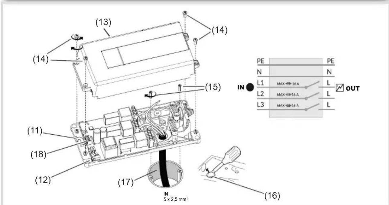
Figure 3: Mounting power control unit
(11) Cut-out and cable entry for potential-free contacts (AUX)
(12) Connection socket for water leakage sensor
(13) Casing cover for power control unit
(14) Fastening screws for casing cover
(15) Device screws for flush-mounted/hollow-wall box (not included in scope of delivery)
(16) Cut-out for flush-mounted installation
(17) Cooker supply cable (not included in scope of delivery)
(18) Connecting terminal for external signal generator (potential-free contacts, AUX)
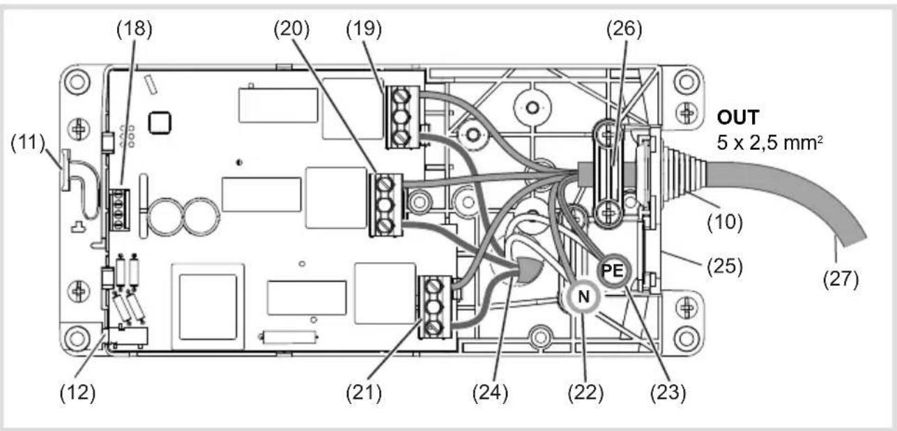
Figure 4: Connection assignment 3-phase
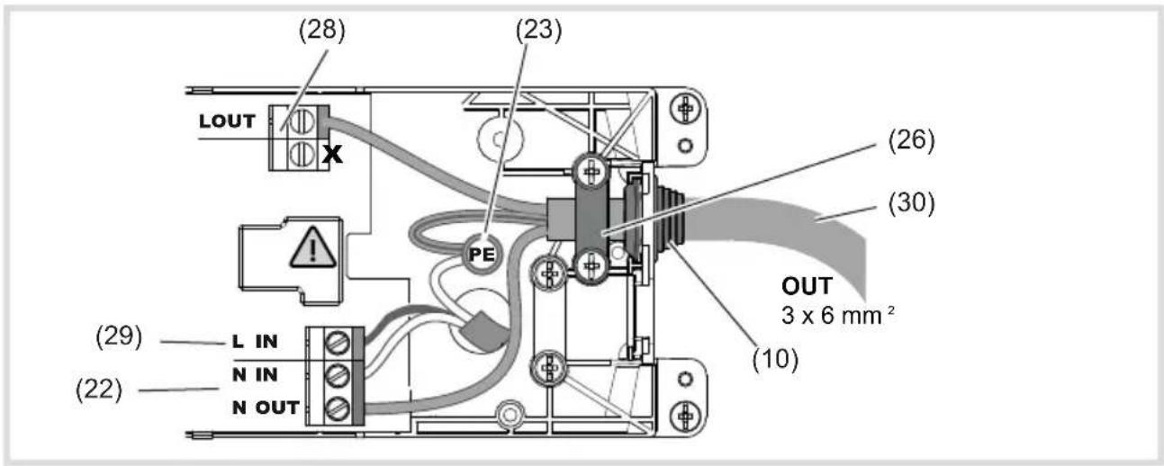
Figure 5: Connection assignment 1-phase
(19) Connecting terminal L3
(20) Connecting terminal L2
(21) Connecting terminal L1
(22) Distribution terminal N
(23) Distribution terminal PE
(24) Entry for cooker supply cable
(25) Additional opening for surface mounting
(26) Strain relief
(27) Connection cable 3-phase for cooker/hob (not included in scope of delivery)
(28) Connecting terminal L OUT (1phase)
(29) Connecting terminal L IN (1phase)
(30) Connection cable 1-phase for cooker/hob (not included in scope of delivery)
Connect power control unit
■ Switch off circuit breaker for cooker/hob.
- Unscrew fastening screws (14) of the casing cover (13) and remove the cover.
- Fix cut-out for the flush-mounted installation (16) or surface-mounted installation (25).
- Unscrew device screws (14) of the flush-mounted/hollow-wall box.
- Insert cooker supply cable (17) into the power control unit (24).
■ Position the power control unit over the flush-mounted/hollow-wall box and fasten with the device screws (15).
In the case of a surface mounting, the cooker supply cable is inserted through the second cut-out (25) and the device e.g. is mounted on the wall behind the cooker.
Connect cookguard 3phase
When connecting a single hob the connecting terminals L1 and L2 are to be assigned.
When connecting a single hob, the free, third wire must be insulated according to the installation regulations.
The N-conductors are connected to the distribution terminal supplied (only 3-phase variant).
■ Connect cooker supply cable 3-phase (17) to the connection terminals IN (19 ... 23) of the power control unit. When doing so, first connect the earth conductor.
- Insert the connection cable (27) through the cable entry (10).
■ Fix strain relief (26).
■ Connect the connection cable 3-phase (27) to the connection terminals OUT (19 ... 23) of the power control unit. When doing so, first connect the earth conductor.
OR:
Connect cookguard 1phase
■ Connect cooker supply cable 1-phase (17) to the connection terminals IN (22/23/29) of the power control unit. When doing so, first connect the earth conductor.
- Insert the connection cable (30) through the cable entry (10).
■ Fix strain relief (26).
■ Connect the connection cable 1-phase (30) to the connection terminals OUT (22/23/28) of the power control unit. When doing so, first connect the earth conductor.
- Optional: Insert water leakage sensor into the connection socket (12) of the power control unit (9) (see Mounting Water Leakage Sensor).
■ Fasten casing cover (13) using the fastening screws (14) on the lower casing.
■ Optional: Connect external signal generator to potential-free contact (18) (Figure 6).
- Switch on circuit breaker again for cooker/hob.
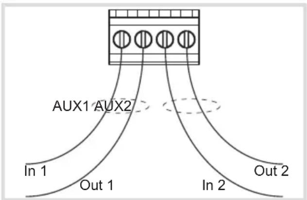
Figure 6: Connecting terminal (AUX) for external signal generator
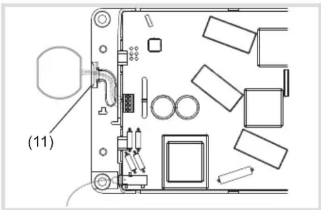
Figure 7: Connect potential-free output
Connect potential-free contacts
The device is equipped with two potential-free outputs AUX1 and AUX2 (18). This allows forwarding of the state of the cookguard to binary inputs of the building automation system or other safety systems (for further information, see Section 4.5).
The AUX outputs are optoinsulated and potential-free. Due to the optocoupler, attention must be paid to the polarity of the scanning voltage of the binary input of the building automation system. The Out terminals must be connected to the earth or earth potential of the binary input.
The scanning voltage between In and Out may be a maximum of 24 VDC and must be at least 3 V. The current between In and Out is to be limited to a maximum of 10 mA.
i Only DC voltage is permitted between the In and Out terminals.
The device to be connected should already be preconfigured.
■ Remove the break-out opening (11) on the housing base (Fig. 7).
■ Connect potential-free output Pay attention to polarity!
- Clamp the cable in the cable routing slot.
Sensor Unit - Selecting installation location
The sensor unit can optionally be mounted on the wall above the cooker/hob or directly under the extractor hood (Figure 8). The sensor unit monitors the temperature and use of the cooker/hob and switches off the power supply in the event of an alarm.
■ Remove mounting bracket (8) carefully from the sensor unit.
- Insert batteries into the sensor unit.
■ Connection to the power control unit is established automatically. If radio connection is successful, the sensor unit emits two acoustic signals for confirmation.
■ Fasten mounting bracket (8) again to the sensor unit.
■ Remove any grease and dirt from the mounting surface using the cleaning pad supplied.
- Attach sensor unit using supplied adhesive stripes (figure 8) (optional: use supplied fastening material).
i Make sure that the sensor is aligned correctly.
In case of cooker widths between 70 ... 90 cm, the alarm limit should be set one level lower as recommended in table 5.
The sensor unit must be mounted in the middle above the cooker/hob.
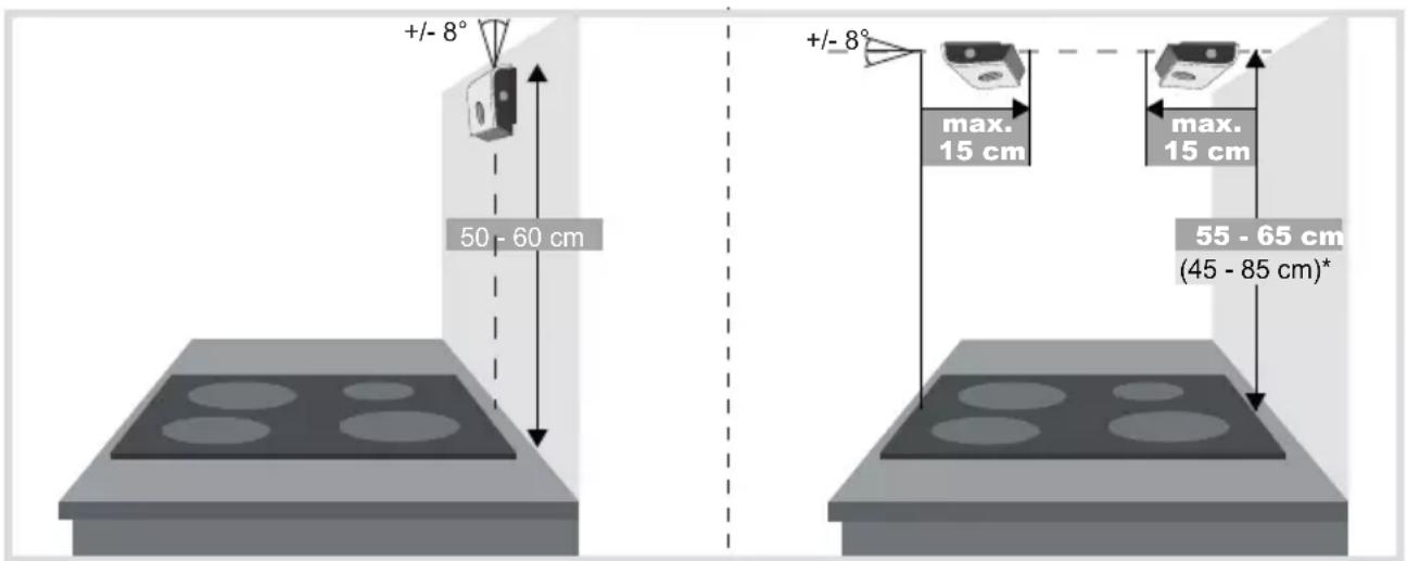
* In the case of installation beyond the standard height of 55 ... 65 cm, the alarm limit must be adjusted accordingly (see Setting alarm limit).
Figure 8: Wall mounting (left); Installation under the extractor hood (right)
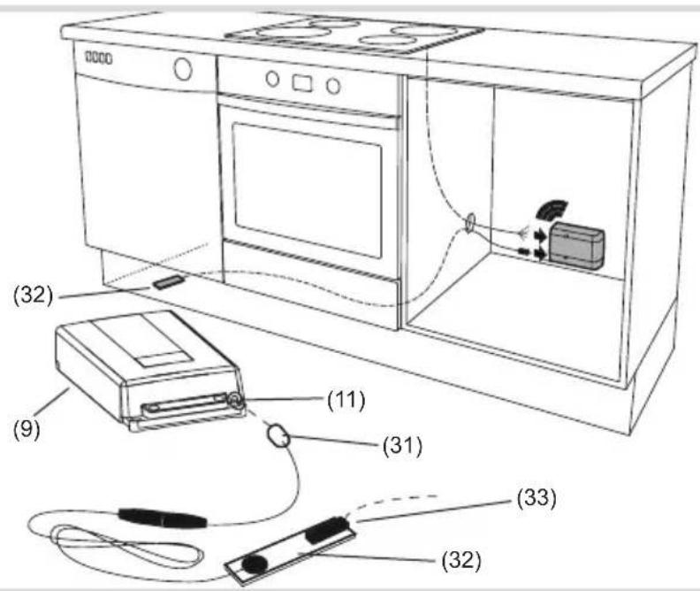
Figure 9: Mounting water leakage sensor
(31) Water leakage sensor plug
(32) Water leakage sensor
Mounting water leakage sensor
The leakage sensors are positioned under the sink, in the area of the dishwasher and in additional places where water leakage is likely.
■ Insert plug of the leakage sensor (31) into the jack on the power control unit (11).
Place the water leakage sensor (32) under the dishwasher (Figure 9).
(33) Connection socket for additional water leakage sensors
■ Optional: Insert additional water leakage sensor into the plug (33) of the front sensor (31).
Testing water leakage sensor
Place a moist cloth on the water leakage sensor.
■ Cookguard triggers test alarm
■ After successful test dry and clean water leakage sensor.
5.2 Commissioning and performing a functional test
A functional test should be carried out by an electrician after installation.
The default settings of the cookguard are to be used for the initial setup. If the mounting height of the sensor unit or the dimensions of the cooker/hob vary from the standard values (Figure 8), then the commissioning must be performed manually (see Manual commissioning).
Performing a functional test
■ Switch on cooker/hob with highest power.
With an induction cooker a suitable pot must be used for commissioning. Keep the operation button (3) pressed for 5 s.
The power supply to cooker/hob is interrupted. Cooker/hob is switched off.
- Check if cooker/hotplate is switched off.
■ Switch off cooker/hob manually via the corresponding hotplate switch.
■ With the cooker/hob switched off, press the operation button (3) once.
The power supply to the cooker/hob is switched on again. Cookguard is ready for operation. Status LED (5) flashes once in green.
5.3 Manual commissioning/Device setting
| Setting mode Setting Colour of status LED (5) | ||
| Mode 1 Setting alarm limit lights up white | ||
| Mode 2 Establishing radio connection flashes purple-blue | ||
| Mode 3 Calibrating cooker type flashes yellow-green | ||
| Mode 4 | Set and test AUX connection | flashes white (normal AUX mode)flashes red (reversed AUX mode) |
Tabele 5. Setting modes
Manual commissioning is necessary if the cooker was replaced, the cooker dimensions and mounting height of the sensor unit vary from the standard values (Figure 8) or if false alarms occur too frequently.
Manual commissioning is performed via four setting modes on the sensor unit:
The setting modes can be changed successively or individually.
- Keep the operation button (2) pressed for 5 s.
Setting mode (1) is active. Status LED (5) lights up white.
■ Press operation button (3) repeatedly until next setting mode is reached.
The Status LED (5) signals the set mode in the appropriate colour.

WARNING!
Risk of accident!
If the setting of the alarm limit is too high, the detection of hazards is delayed. Do not set alarm limit higher than 8 during the installation!
| Colour of status LED (5) | Number of acoustic signals | Alarm limit Installation height: Wall mounting | Installation height: Installation under the extractor hood |
| red | ●●● ●●● 12 | ||
| ●●● ●● 11 | |||
| ●●● ● 10 | |||
| ●●● | 9 | ||
| ●● 8 | |||
| ● | 7* | 45 ... 55 cm | |
| blue | ●●● ●●● | 6(Standard)* | 50 ... 60 cm |
| ●●● ●● | 5* | 65 ... 75 cm | |
| ●●● ● | 4* | 75 ... 85 cm | |
| ●●● | 3 | ||
| ●● 2 | |||
| ● | 1 |
* recommended alarm limits
Table 6: Alarm limits
Setting mode 1: Setting alarm limit
The alarm limit is preset to 6 in default state.
This means that the sensor unit is mounted at a height of 50 ... 60 cm (wall mounting) or 55
... 65 cm (mounting under the extractor hood). If the mounting heights vary from the standard, the alarm limit (Table 5) must be adjusted.
The recommended alarm limit (4 - 7) depends on the position of the cooker, installation height, installation mode and reaction behaviour of the sensor unit. The values are between 1 and 12 (1 = fastest reaction, 12 = slowest reaction).
The setting mode 1 is activated. The status LED lights up white.
- Select suitable, recommended alarm limits from Table 6.
■ Press operation button (2).
The next higher level is set and the setting mode 1 is left.
OR:
■ Press operation button (1).
The next lower alarm limit is set and the setting mode 1 is left.
The new alarm limit is displayed according to the data in Table 6 and signalled via the colour of the Status LED and the number of tones.
To set another alarm limit the setting mode 1 has to be called up.
Setting mode 2: Establishing radio connection
Setting mode 2 is called up. The status LED (5) flashes twice purple-blue.
- Switch off circuit breaker of the cooker/hob for 10 s.
■ Switch on fuse again.
The power control unit searches for the sensor unit automatically.
If connection is successful, the sensor unit acknowledges with three acoustic signals
(●●●). The cookguard ends the automatic setting mode.
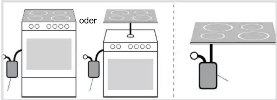
Figure 10: Calibrating cooker type manually
Setting mode 3: Calibrating cooker type
Setting mode 3 is called up. The status LED (5) flashes yellow-green.
Two selection options are available for calibrating the cooker type.
Option 1: Cooker and oven are jointly connected to the power control unit (Figure 10, left).
Switch on oven.
■ Press operation button (1).
The sensor unit confirms the identification of the cooker type with acoustic and optical signals.
■ Switch off oven.
Manual calibration in option 1 is completed.
Option 2: Hob is connected individually to the power control unit (Figure 10, right).
- Switch on the most powerful hotplate to the highest level.
■ Press operation button (2).
The sensor unit confirms the identification of the cooker type with acoustic and optical signals.
■ Switch off hotplate.
Manual calibration in option 2 is completed.
The cookguard ends the automatic setting mode.
With an induction cooker a suitable pot must be used for commissioning.
Setting mode 4: Setting and testing potential-free contacts
Additional information about the two potential-free outputs AUX1 and AUX2 can be found in chapter 4.5.
Setting mode 4 is called up. The status-LED (5) flashes white (normal setting) or red (inverted setting).
■ Press operation button 1 (1) for five seconds.
Changing between the two operation modes of the AUX outputs:
Normal AUX mode: The status LED (5) flashes white.
Inverted AUX mode: The status LED (5) flashes red.
Testing AUX outputs:
■ Short press on operation button (1).
AUX1 changes bewtween ON and OFF
■ Short press on operation button (2).
AUX2 changes bewtween ON and OFF
To terminate the setting mode 4.
■ Press operation button (3).
The setting mode is completed.
5.4 Changing colour strips of the sensor unit
The sensor unit can be adapted to match the colour of the wall using the colour strips supplied.
■ Remove sensor unit carefully from the mounting bracket (8).
■ Remove front cover (6) by lifting at the back of the sensor unit.
- Attach the desired colour strips to the sensor unit.
When attaching the colour strips to the sensor unit, make sure that no sensor is covered.
- Fasten transparent front cover to the sensor unit.
■ Press sensor unit onto the mounting bracket (8).
6 Appendix
6.1 Technical data
Sensor unit
Battery type AA/LR6 Alkaline
Recommended battery type Duracell Ultra
Power (MX1500)
Battery service life 3 ... 5 years
Sound pressure at a distance of 1 m 70 ... 75 dB (A)
Radio frequency 2.4 GHz
Range 10 ... 100 m,
depending on building structure
Dimensions (W x H x D) 125 x 17 x 45 mm
Degree of contamination 2
Power control unit
Rated voltage, 3phase 400 V
Rated current, 3phase 3 x 16 A
Conductor cross-section, 3phase 5 x 2.5 mm²
Rated voltage, 1phase 230 V
Rated current, 1phase 1 x 25 A
Conductor cross-section, 1phase 3 x 6 mm ^4
Energy consumption 4 W
Degree of contamination 2
Rated surge voltage 4 kV
Operating temperature +5 ... +35°C
Ball pressure test 100 °C
Creep resistance (PTI) 175 ... 400
Number of switching operations approx. 6000
Degree of protection IP20
Dimensions (L x W x H) 239 x 113 x 42 mm
Standard IEC/EN 60730-1: Type 1.B
DIN EN 50615
Potential-free contacts
Rated voltage DC 3 ... 24 V
Rated current max. 10 mA
6.2 Troubleshooting
Power supply to the cooker is switched off.
Cause 1: Battery level of the sensor unit is too low. Battery display (7) flashes.
Replace batteries.
Cause 2: Mounting position of the sensor unit is wrong and the status LED (5) flashes yellow (●●●).
Check mounting position of the sensor unit and adjust if necessary (Figure 7).
Cause 3: Radio connection is interrupted and status LED (5) flashes blue (●).
Establish radio connection manually in setting mode 2 (see Manual commissioning).
Cause 4: Power control unit is overheated and status LED (5) flashes blue (●●●).
Let the device cool down for a while. If it occurs again, contact an electrician.
Cause 5: Problem with the sensor unit and status LED (5) flashes yellow (●●).
Check batteries or have sensor unit checked.
Cause 6: Problem with the sensors and status LED (5) flashes yellow (●).
Clean sensor unit and sensors carefully.
Power supply to the cooker is switched off and switched on again immediately.
Cause: Power control unit is connected incorrectly.
Check that the connection of the cooker supply cable and cooker connection cable have the right terminal assignment (IN/OUT).
Water leakage alarm triggers.
Cause: The leakage sensor is not sufficiently dried or is dirty.
Dry or clean water leakage sensor.
Sensor unit does not react when button is pressed.
Cause 1: Battery charge too low.
Replace batteries.
Cause 2: Batteries are not inserted correctly.
Check that the batteries are in the correct position according to the marking on the bottom of the battery compartment and correct the position if necessary.
The fault signals that possibly occurred and their problem description are listed in table 7.
Fault status query
Fault status query by pressing the operation button (3).
The status LED (5) flashes green if there is currently no fault.
The status LED flashes blue or yellow if a fault occurs. The fault signals and problem descriptions are listed in table 7 below.
| Status LED (5) flashes blue Problem description | |
| ● Problem with the radio connection | |
| ●● Problem with the power control unit | |
| ●●● Power control unit is overheated | |
| Status LED (5) flashes yellow Problem description | |
| ● Problem with the sensors | |
| ●● Problem with the sensor unit | |
| ●●● Wrong mounting position of the sensor unit | |
Table 7: Fault signal
Note:
Should it not be possible to eliminate a problem immediately, the cooker can be used temporarily for 1.5 hours at any time, by removing the batteries from the sensor
unit and switching the fuses for the cooker off for 10 seconds and then switching them on again.
In this emergency mode, the protection function is not available!
6.3 Accessories
Water leakage sensor WXH202
KNX radio binary input 2gang flush-mounted
TRM702A
KNX radio binary input TRB302B
2gang flush-mounted 230 V
„Hager cookguard with Safera technology inside“
Sommaire
Dimensions (I x H x P) 125 x 17 x 45 mm
„Hager cookguard with Safera technology inside“
Inhoud
„Hager cookguard with Safera technology inside“
Contenuto
Dimensioni (L x A x P) 125 x 17 x 45 mm
„Hager cookguard with Safera technology inside“

- WXH20xWXH21x
- Content
- Operating and assembly instructions 21
- Cookguard 1phase
- Cookguard 3phase
- Operating and assembly instructions
- This document is only valid for devices with manufacturing dates after 09/2019
- Safety instructions
- Design and layout of the device
- Scope of delivery
- Function
- Function notes
- Correct use
- Product characteristics
- Operation
- Operating concept and display elements
- Setting alarm limit
- Automatic child lock
- Switching on child lock
- Dangerous situations
- Pre-alarm has tripped
- Switching off child lock
- Switching on cooker with activated child lock
- Switching off the cooker
- Alarm confirmation by tapping the sensor unit (optional)
- Activating/deactivating the tap function:
- Water leakage sensor (optional)
- Procedure with water leakage sensor:
- Potential-free contacts (optional)
- Information for electricians
- Installation and electrical connection
- DANGER!
- Connect power control unit
- Connect cookguard 3phase
- Connect cookguard 1phase
- Connect potential-free contacts
- Sensor Unit - Selecting installation location
- Mounting water leakage sensor
- Commissioning and performing a functional test
- Performing a functional test
- Manual commissioning/Device setting
- WARNING!
- Setting mode 1: Setting alarm limit
- Setting mode 2: Establishing radio connection
- Setting mode 3: Calibrating cooker type
- Setting mode 4: Setting and testing potential-free contacts
- Changing colour strips of the sensor unit
- Appendix
- Technical data
- Sensor unit
- Power control unit
- Potential-free contacts
- Troubleshooting
- Power supply to the cooker is switched off.
- Power supply to the cooker is switched off and switched on again immediately.
- Water leakage alarm triggers.
- Sensor unit does not react when button is pressed.
- Fault status query
- Note:
- Accessories
- Sommaire
- Inhoud
- Contenuto
Brand : HAGER
Model : WXH202
Category : Smoke detector