
BM240S1A - Motion detector JUNG - Free user manual and instructions
Find the device manual for free BM240S1A JUNG in PDF.
| Product type | Passive infrared motion detector |
| Brand | JUNG |
| Model | BM240S1A |
| Dimensions (H x W x D) | 84 x 89 x 90 mm |
| Power supply | AC 230-240 V ~, 50 Hz |
| Max. load power | 1000 W (incandescent/halogen lamps) |
| Horizontal detection angle | 240° |
| Vertical detection angle | 180° |
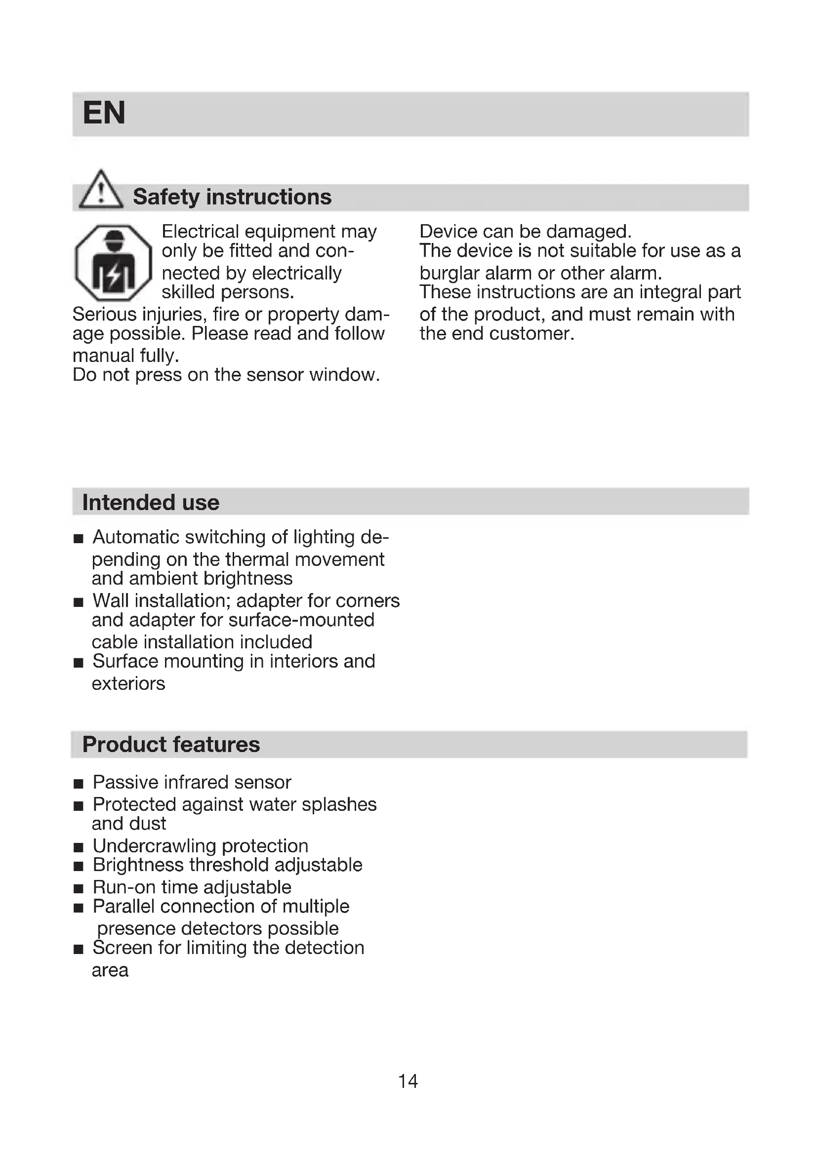
| Max. range | 12 m |
| Recommended mounting height | 1.8 to 4 m |
| Adjustable time delay | 10 s to 15 min |
| Adjustable brightness threshold | 2 to 2000 lux |
| Protection rating | IP 54 |
| Housing orientation | ±80° (horizontal) |
| Main functions | Automatic lighting control, anti-creep protection, covers for delimiting detection area |
| Mounting | Wall-mounted (indoor and outdoor) with corner adapter included |
| Connection | Parallel connection of multiple detectors possible |
| Care and cleaning | Clean the lens with a damp cloth, no detergent |
| Safety | Installation by qualified electricians only; disconnect the device before any intervention |
| Recycling | Device, accessories, and packaging must be recycled separately |
Frequently Asked Questions - BM240S1A JUNG
User questions about BM240S1A JUNG
0 question about this device. Answer the ones you know or ask your own.
Ask a new question about this device
Download the instructions for your Motion detector in PDF format for free! Find your manual BM240S1A - JUNG and take your electronic device back in hand. On this page are published all the documents necessary for the use of your device. BM240S1A by JUNG.
USER MANUAL BM240S1A JUNG
natural_image
Close-up of a white plastic mechanical component with a spherical base and stepped shaft (no text or symbols visible)natural_image
Line drawing of a house with circular structure and radial lines, labeled '200 m²' at bottom (no other text or symbols)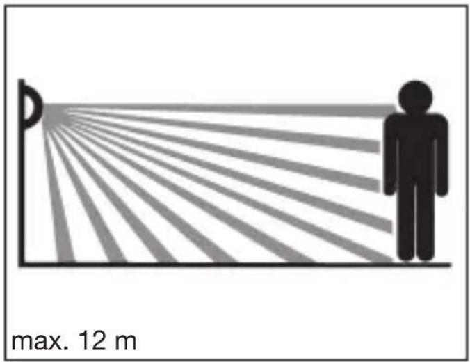
text_image
max. 12 m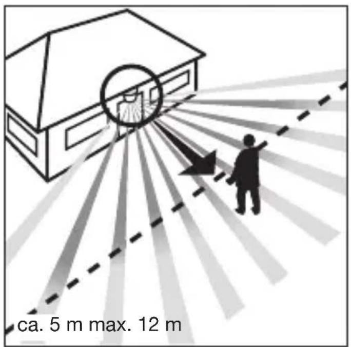
text_image
ca. 5 m max. 12 m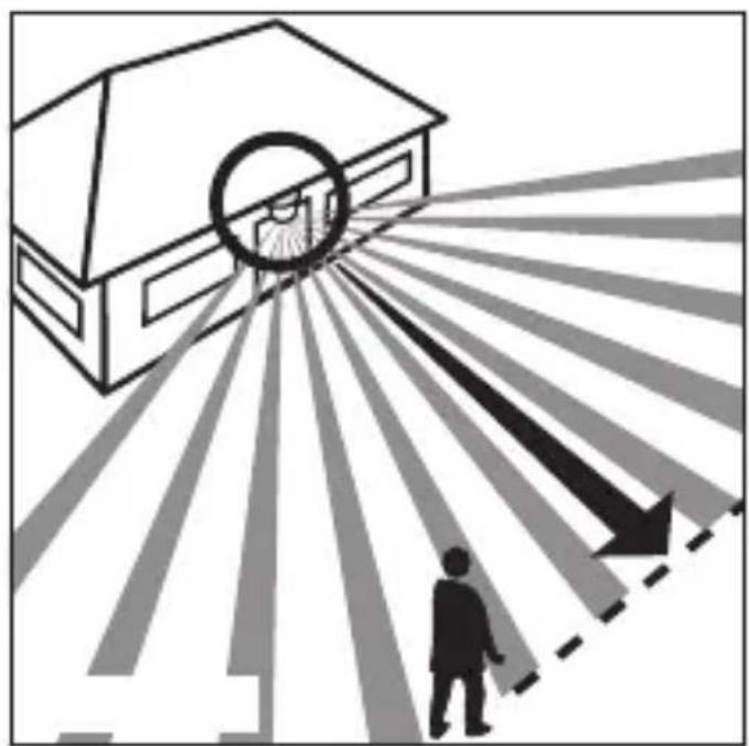
natural_image
Illustration of a building with a circular target and directional arrows, showing a person walking toward it (no text or symbols)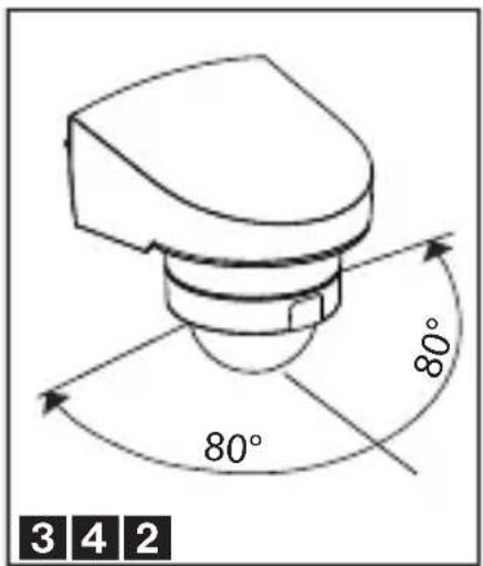
text_image
80° 80° 3 4 2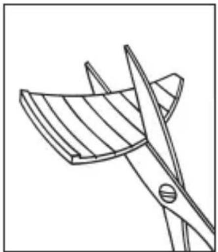
natural_image
Line drawing of a bird cutting a bird wing with scissors (no text or symbols)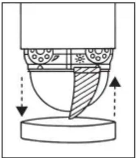
natural_image
Technical diagram of a mechanical assembly with directional arrows indicating motion or force (no text or symbols)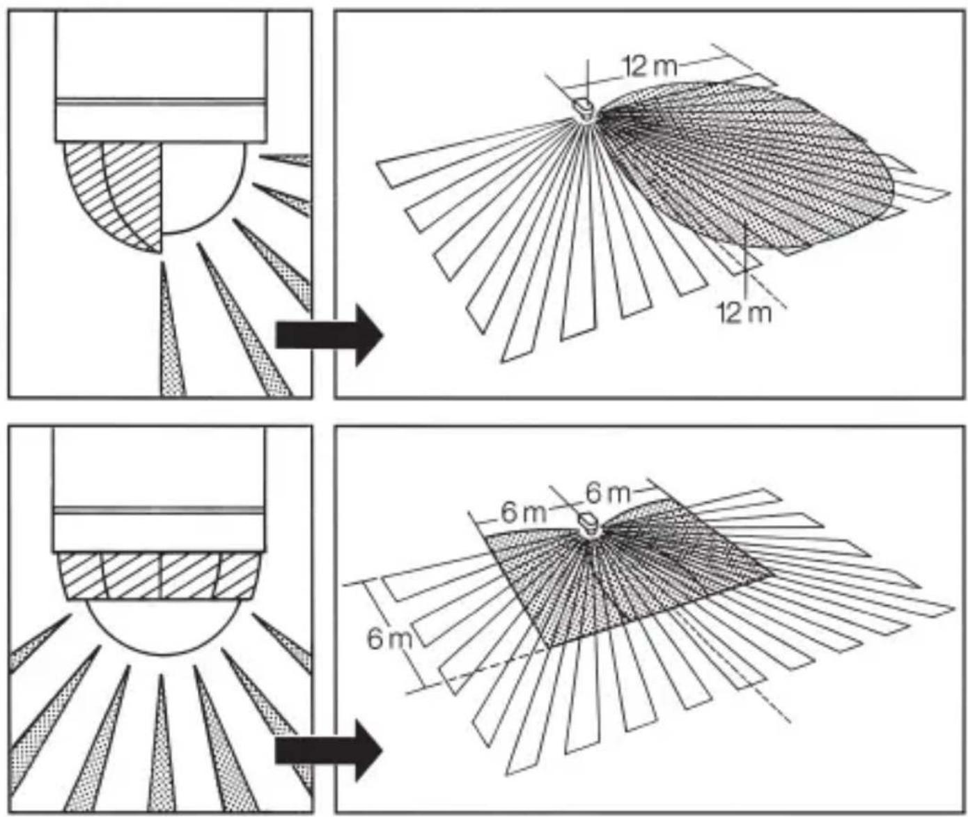
DE
Sicherheitshinweise
Electrical equipment may only be fitted and connected by electrically skilled persons.
Serious injuries, fire or property damage possible. Please read and follow manual fully.
Do not press on the sensor window.
Device can be damaged.
The device is not suitable for use as a burglar alarm or other alarm.
These instructions are an integral part of the product, and must remain with the end customer.
Intended use
■ Automatic switching of lighting depending on the thermal movement and ambient brightness
■ Wall installation; adapter for corners and adapter for surface-mounted cable installation included
■ Surface mounting in interiors and exteriors
Product features
■ Passive infrared sensor
■ Protected against water splashes and dust
■ Undercrawling protection
■ Brightness threshold adjustable
■ Run-on time adjustable
■ Parallel connection of multiple presence detectors possible
■ Screen for limiting the detection area
Installation
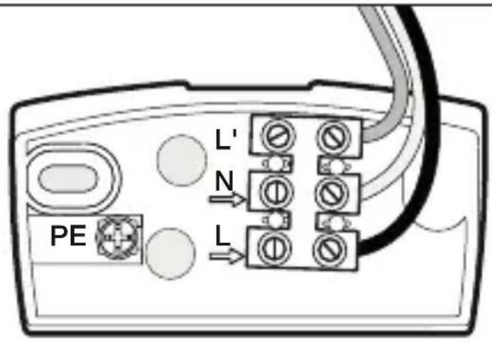
text_image
L' N PE LL = Phase conductor
N = Neutral conductor
L' = Service lead
PE = Protective-earth conductor
Information for electrically skilled persons
Installation and electrical connection
DANGER
Electrical shock on contact with live parts in the installation environment.
Electrical shocks can be fatal.
Before working on the device, disconnect the power and cover live parts in the area.
Wall mounting
Important: The safest motion detection is obtained when the device is mounted and aligned laterally to the walking direction and no obstacles (such as trees and walls, for example) obstruct the view.
Please note that the motion detector must be protected by a 10 A circuit breaker.
The installation site should be at least 50 cm from a light, since the latter's
heat radiation could result in false triggering of the sensor. The installation height should be approx. 2 m.
Remove mounting plate 1 from device. Do not undo the internal wiring to the terminal block, but extract the block by pulling it gently.
Insert the rubber plugs into the mounting plate. Hold the mounting plate against the wall and mark the drill holes (paying attention to the wiring arrangement in the wall), drill the holes and insert the dowels.
In order to be able to perform a switching operation, a power supply lead with at least two phases must run to the unit and a second lead out to the consumer. The two rubber plugs can be pierced for this purpose with a screwdriver.
After passing the wiring through, the mounting plate can be screwed in place.
Connection of the mains lead
The mains lead consists of a 2 or 3 pole cable.
L = Phase conductor (usually black, brown or grey) N = Neutral conductor (usually blue)
PE = Protective-earth conductor, if present (green/yellow)
If in doubt, the cable must be identified with a voltage tester. Switch off the current again. The wire terminals are for the mains lead. The phase conductor (L) connects into the lower terminal and the neutral conductor (N) connects into the middle terminal.
If the green/yellow protective-earth conductor is present, connect this to the bottom terminal provided.
Connection of the service lead
The service lead (e.g. light) likewise consists of a 2 or 3 pole cable which is connected to terminals N and L'. The phase conductor of the consumer (black, brown or grey cable) is connected to the terminal marked L'. The neutral conductor (blue cable) is clamped to the terminal marked N together with the mains lead neutral conductor. Connect any green/yellow protective-earth conductor to the lower terminal.
Important: Getting the cable connections crossed will produce a short circuit in the unit or in your fuse box. In this case, the individual wires must be re-identified and reconnected. A mains switch for ON and OFF switching can of course be installed in the mains lead.
Wiring examples
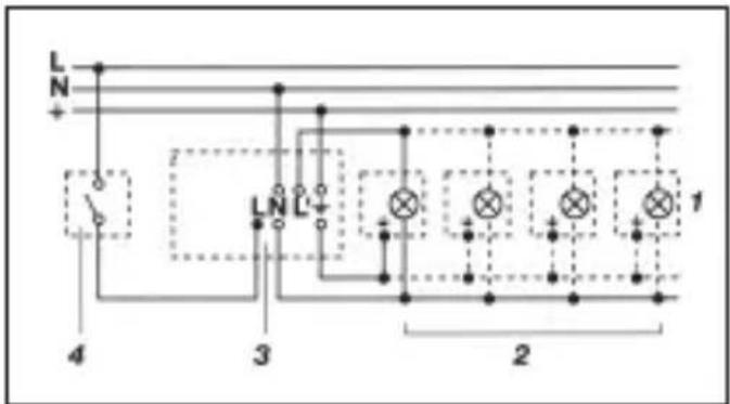
text_image
L N + 4 3 LN L - 2 1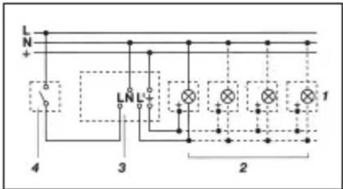
text_image
L N + 4 3 LNL+ 2 1- Fixture without neutral conductor 2. Fixture with neutral conductor
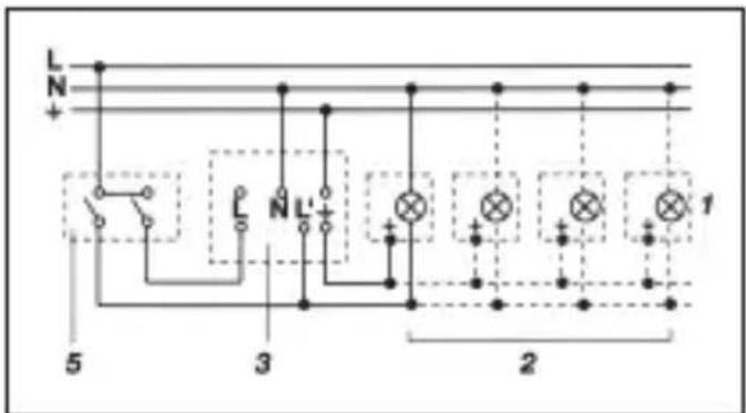
text_image
L N + L N L' + 5 3 2 1- Connection via series switch for manual and automatic operation
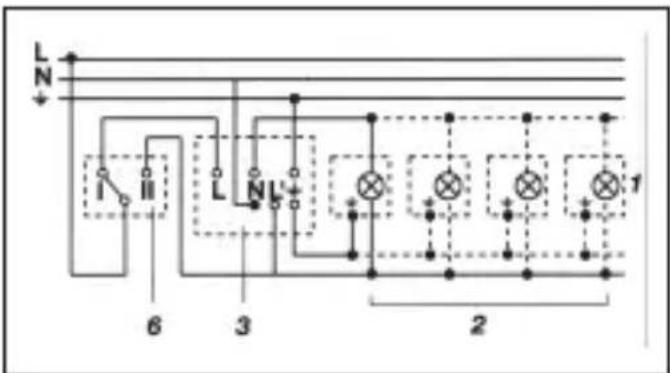
text_image
L N 6 3 2 1- Connection to double-throw switch for permanent light and automatic operation
Setting I:
automatic operation
Setting II:
manual operation for permanent light
Important:
The unit cannot be switched off, only optional operation between settings I and II.
1) e.g. one to four incandescent lamps with 100 W
2) consumer, lighting max. 1000 W (refer to Technical specifications)
3) connection terminals of the motion detector
4) indoor switch
5) indoor series switch, manual, automatic
6) indoor double-throw switch, automatic, permanent light
Function
After the motion detector has been connected and fastened to its wall mount, the system can be switched ON.
Two setting options are available after removing the decorative ring 2.
text_image
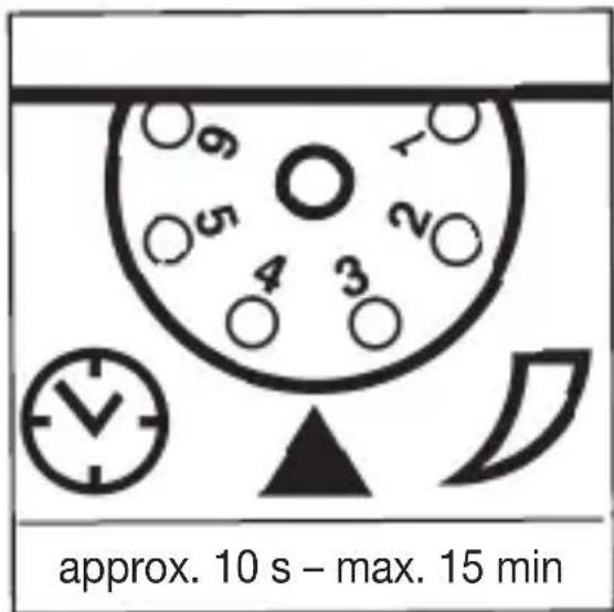
approx. 10 s - max. 15 minSwitch-off delay (time setting)
(Factory setting: 10 s)
Light ON duration can infinitely varied from approx. 10 s to a maximum of 15 min
Control dial set to (1) = shortest time (10 s)
Control dial set to (6) = longest time (15 min)
The shortest time setting is recommended when adjusting the detection zone and performing the function test.
text_image
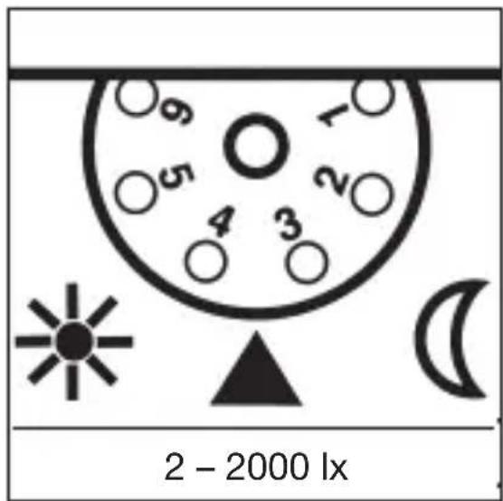
2 - 2000 lxTwilight setting
(Factory setting: 2000 lx)
The sensor's response threshold can be infinitely varied from 2 - 2000 lx
Control dial set to (1) = daylight operation at approx. 2000 lx
Control dial set to (6) = night-time operation at approx. 2 lx
The adjusting screw must be turned fully anti-clockwise when adjusting the detection zone and performing the function test in daylight.
Reach setting/adjustment
Assuming an installation height of 2 m, the maximum reach of the sensor is 12 m. Optimum adjustment of the detection zone is possible according to needs. The shrouds 4 provided serve to cover any desired number of lens segments and individually reduce the reach. Fine adjustment is also possible by turning the sensor housing 3 by ± 80°. The shrouds 4 can be divided vertically or horizontally
along the grooved divisions, or cut with scissors. After removing the decorative ring 2, the shrouds are to be suspended on the upper part of the sensor lens. The decorative ring 2 is subsequently to be reapplied and the shrouds 4 are fixed firmly in place. False switching by cars and pedestrians, etc. is therefore ruled out, or risk areas deliberately monitored.
Technical specifications
| Dimensions (H x W x D): 84 x 89 x 90 mm | ||
| Mounting height: 1.8 ... 4 m | ||
| Output: | ||
| Incandescent / halogen lamp load 1000 W | ||
| Fluorescent-lamp electronic ballasts 1000 W | ||
| Fluorescent lamps, uncorrected 500 W | ||
| Fluorescent lamps, parallel-corrected 500 W | ||
| Low-voltage halogen lamps 1000 VA | ||
| LED < 2 W 16 W | ||
| 2 W < LED < 8 W 64 W | ||
| LED > 8 W 64 W | ||
| Capacitive load 132 μF | ||
| Capacitive load 132 μF | ||
| Connection: AC 230 ... 240 V ~, 50 Hz | ||
| Angle of coverage: horizontal | 240° | |
| vertical | 180° | |
| Adjusting possibilities: | rotating | 160° horizontal |
| Reach: | max. 12 m (electronically stabilised) | |
| Time setting: | approx. 10 s ... 15 min | |
| Brightness setting: | approx. 2 ... 2000 lx | |
| IP rating: | IP 54 | |
Troubleshooting
Malfunction Cause Remedy
| Motion detector without power | ■ Fuse has blown; not switched ON■ Short-circuit | ■ Replace fuse, switch ON mains switch, check wiring with voltage tester■ Check connections |
| Motion detector does not switch ON | ■ Twilight setting in night-time mode during daytime operation■ Bulb burned out■ Power switch OFF■ Fuse blown■ Detection zone not correctly adjusted | ■ Adjust setting■ Replace light bulb■ Switch ON■ Replace fuse, check connection if necessary■ Readjust |
| Motion detector does not switch OFF | ■ Continued movement within the detection zone■ Switched ON light is within detection zone and switches ON again as a result of temperature change■ Set to continuous operation by indoor series switch■ Position Wi-Fi device very close to the sensor | ■ Check zone and readjust if necessary or apply shroud■ Readjust zone or apply shroud■ Series switch to automatic■ Increase distance between Wi-Fi device and sensor |
| Motion detector keeps switching ON/OFF | ■ Switched ON light is within detection zone■ Animals moving in detection zone | ■ Adjust detection zone or apply shrouds, increase distance■ Adjust zone or apply shrouds |
Malfunction Cause Remedy
| Motion detector switches ON when it should not | ■ Wind is moving trees and bushes in the detection zone■ Cars in the street are detected■ Sudden temperature changes due to weather (wind, rain, snow) or exhaust air from fans or open windows■ Position Wi-Fi device very close to the sensor | ■ Adjust zone or apply shrouds■ Adjust zone or apply shrouds■ Adjust detection zone or install in a different place■ Increase distance between Wi-Fi device and sensor |
Maintenance/care
The motion sensor is suitable for automatic switching of lights or alarms. The unit is not suitable for special burglary alarm systems, since it lacks the sabotage protection prescribed for this purpose. Weather can affect operation of the sensor.
Strong gusts of wind, snow, rain and hail can cause switching errors, since the sudden temperature changes cannot be distinguished from heat sources. The detection lens 5 can be cleaned with a damp cloth (without detergents) if dirty.
Disposal

The symbol with the crossed-out wheeled bin indicates that the product must be disposed of separately from household waste at the end of its useful service life in order to enable correct treatment and recycling.
At the end of its service life, the user must therefore take the device free of charge to the municipal collection points responsible for the separate collection of electrical and electronic waste or return it to the dealer.
Separate collection for recycling helps to avoid possible negative impacts on the environment and health, and facilitates the reuse, recycling and/or recovery of the materials in the devices.
Wherever possible, batteries and rechargeable batteries must be removed from the device prior to disposal.
Manufacturer's warranty
The warranty follows about the specialty store in between the legal framework as provided for by law.
NL

text_image
L N 6 3 2 1N = Conductor neutro