
PS 12 Niro - Heating EINHELL - Free user manual and instructions
Find the device manual for free PS 12 Niro EINHELL in PDF.

| Product type | Outdoor heater (patio heater) |
| Brand | Einhell |
| Model | PS 12 Niro |
| Total height | 2300 mm |
| Reflector diameter | 780 mm |
| Power | 12 kW |
| Gas consumption | 0.946 kg/h |
| Energy supply | Liquid gas (propane/butane) |
| Bottle connection | Gas bottle up to 11 kg |
| Ignition | Piezoelectric |
| Flame monitoring | Thermoelectric |
| Material | Stainless steel (Niro) |
| Use | Outdoors or well-ventilated room (20 m²/kW) |
| Safety distance | 2 meters from flammable materials |
| Maximum ground inclination | 5° |
| Approximate weight | Approx. 25 kg (empty) |
| Cleaning | Non-abrasive and non-flammable liquids |
| Maintenance | Check seal and hose every 6 months |
| Warranty | 2 years |
| Spare parts | Available from ISC GmbH |
Frequently Asked Questions - PS 12 Niro EINHELL
User questions about PS 12 Niro EINHELL
0 question about this device. Answer the ones you know or ask your own.
Ask a new question about this device
Download the instructions for your Heating in PDF format for free! Find your manual PS 12 Niro - EINHELL and take your electronic device back in hand. On this page are published all the documents necessary for the use of your device. PS 12 Niro by EINHELL.
USER MANUAL PS 12 Niro EINHELL
Detail A
Detail B
Detail C
Detail D
Detail E
Detail F
Detail G Detail H
1. PS 12 NIRO
 | Detail A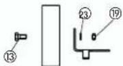 | Detail B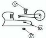 |
Detail C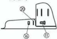 | Detail D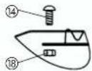 | |
Detail E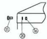 | Detail F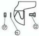 | |
Detail G Detail H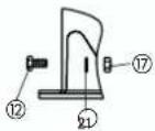 | 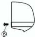 | |
 | ||
2
4
Read the safety and operating instructions carefully before you use your heater for the first time. Material and features have been selected to rule out malfunctions provided the heater is used as intended. Check that all parts are complete. Caution: Use only outdoors or in well-ventilated areas!
1. Description
The party heater is used outdoors to heat nearby areas. A burner inside the perforated plate body produces the necessary heat, which is radiated to the immediate surroundings by an aluminium reflector as well as by the perforated plate itself. The party heater has to be set up on a level, incombustible surface with no - or only a very slight - gradient. Its center of gravity can be lowered considerably by filling sand in the foot. To make it easier to change the gas bottle, the body can be raised and locked in place on the appliance itself. The party heater is designed to work only with propane-butane (liquefied gas). It is connected directly to the gas bottle by means of a DVGW-tested and approved hose pipe and a liquefied gas regulator (outlet pressure 28-30/37 mbar, capacity 1,5 kg/h). The following regulations have to be observed and adhered to when making the connection:
● Technical regulations concerning liquefied gas (e.g. TRF)
● Guidelines published by liability insurance associations concerning the use of liquefied gas in special applications
2. Technical data
Dimensions Overall height: 2300 mm
Reflector diameter: 780 mm
Power rating: 12 kW
Consumption: approx. 0,946 kg/h
Fuel: Propane/butane liquefied gas
Ignition: Piezo igniter
Monitoring: Thermoelectric flame monitor
Gas supply Gas bottles up to 11 kg
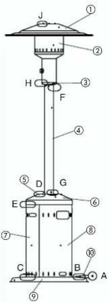
3. Items supplied
3.1 PS 12
| Item 1 Reflector 1 piece | |
| Item 2 Burner, complete 1 piece | |
| Item 3 Adapter plate 1 piece | |
| Item 4 Column 1 piece | |
| Item 5 Container cover | 1 piece |
| Item 6 Container jacket | 1 piece |
| Item 7 Bulkhead | 1 piece |
| Item 8 Foot | 1 piece |
| Item 9 Foot base | 1 piece |
| Item 10 Allen screw size M 5 x 12 | 8 piece |
| Item 11 Allen screw size M 6 x 12 | 10 piece |
| Item 12 Allen screw size M B x 45 | 2 piece |
| Item 13 Parker screw size 3.9 x 9.5 | 4 piece |
| Item 14 Hexagon nut size M 5 | 8 piece |
| Item 15 Hexagon nut size M 6 | 7 piece |
| Item 16 Stop nut size M 8 | 2 piece |
| Item 17 Washer size DM 5.3 | 8 piece |
| Item 18 Washer size DM 6.4 | 9 piece |
| Item 19 Washer size DM 6.4 large | 1 piece |
| Item 20 Washer size DM 8.4 | 2 piece |
| Item 21 Wheels | 2 piece |
3.2 PS 12 Niro
| Item 1 | Reflector | 1 piece |
| Item 2 | Burner, complete 1 piece | |
| Item 3 | Adapter plate 1 piece | |
| Item 4 | Column 1 piece | |
| Item 5 | Washer 1 piece | |
| Item 6 | Container cover | 1 piece |
| Item 7 | Container jacket | 1 piece |
| Item 8 | Bulkhead | 1 piece |
| Item 9 | Foot | 1 piece |
| Item 10 | Foot base | 1 piece |
| Item 11 | Allen screw size M 5 x 12 | 8 piece |
| Item 12 | Allen screw size M 6 x 12 | 10 piece |
| Item 13 | Allen screw size M 8 x 45 | 2 piece |
| Item 14 | Raised cheesehead screw size M 8 x 20 | 3 piece |
| Item 15 | Parker screw size 3.9 x 9.5 | 4 piece |
| Item 16 | Hexagon nut size M 5 | 8 piece |
| Item 17 | Hexagon nut size M 6 | 7 piece |
| Item 18 | Hexagon nut size M 8 | 3 piece |
| Item 19 | Stop nut size M 8 | 2 piece |
| Item 20 | Washer size DM 5.3 | 8 piece |
| Item 21 | Washer size DM 6.4 | 9 piece |
| Item 22 | Washer size DM 6.4, large | 1 piece |
| Item 23 | Washer size DM 8.4 | 2 piece |
| Item 24 | Wheels | 2 piece |
| Item 25 | Edge strip size 360 | 1 piece |
| Item 26 | Edge strip size 245 | 3 piece |
You will need the following additional tools for the installation:
GB
GB
1 wrench SW 8, SW 10, SW 14, SW 17 1 Phillips screwdriver
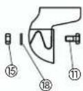
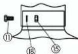
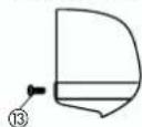
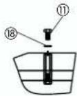
4. Assembly (Fig. 1)
Important: The item numbers in the text refer to the item numbers in sections 3.1 or 3.2
4.1 PS 12
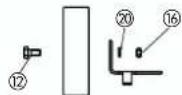
- Fit the wheels (21) to the foot base (9) with two Allen screws (12), two washers (20) and stop nuts (16). (Detail in Fig. A)
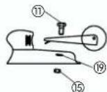
- Screw the foot base (9) to the foot (8) with one Allen screw (11), corresponding washer (19) and one hexagon nut (15). (Detail in Fig. B)
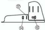
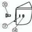
- Screw the container jacket (6) to the foot (8) with four Allen screws (10) and corresponding washers (17) and hexagon nuts (14). (Detail in Fig. C)
- Place the container cover (5) on the container jacket (6) and screw together with four Allen screws (10) and corresponding washers (17) and hexagon nuts (14). (Detail in Fig. D)
- Screw the adapter plate (3) to the top of the column (4) with three Allen screws (11) and corresponding washers (18) and three hexagon nuts (15). (Detail in Fig. E)
- Place the column (4) on the container cover (5) and screw tightly together with three Allen screws (11) and corresponding washers (18) and three hexagon nuts (15). (Detail in Fig. F)
- Feed the hose through the column (4), fit the burner (2) to the adapter plate (3) and screw together with four Parker screws (13). (Detail in Fig. G)
- Screw the reflector (1) to the burner (2) with three Allen screws (11) and corresponding washers (18). (Detail in Fig. H)
- Fit the bulkhead (7).
- Attach to gas cylinder as described in section 6.
4.2 PS 12 Niro
Take particular care when assembling sharp-edged parts!
- Fit the wheels (24) to the foot base (10) with two Allen screws (13), two washers (23) and stop nuts (19). (Detail in Fig. A)
- Screw the foot base (10) to the foot (9) with one Allen screw (12), corresponding washer (22) and one hexagon nut (17). (Detail in Fig. B)
- Screw the container jacket (7) to the foot (9) with 10
four Allen screws (11) and corresponding washers(20) and hexagon nuts (16). (Detail in Fig. C)
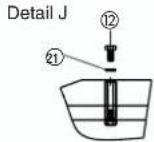
- Screw the washer (5) to the container cover (6) from below with three raised cheesehead screws (14) and corresponding hexagon nuts (18). (Detail in Fig. D)
- Place the container cover (6) on the container jacket (7) and screw together with four Allen screws (11) and corresponding washers (20) and hexagon nuts (16). (Detail In Fig. E)
- Screw the adapter plate (3) to the top of the column (4) with three Allen screws (12) and corresponding washers (21) and three hexagon nuts (17). (Detail in Fig. F)
- Fit the column (4) to the container cover (6) and screw together firmly with three Allen screws (12) and corresponding washers (21) and three hexagon nuts (17). (Detail in Fig. G)
- Feed the hose through the column (4), fit the burner (2) to the adapter plate (3) and screw together with four Parker screws (15). (Detail in Fig. H)
- Screw the reflector (1) to the burner (2) with three Allen screws (12) and corresponding washers (21). (Detail in Fig. J)
- Fit the bulkhead (8).
- Fit the edge strips to the bulkhead (8) and the container jacket (7).
- Attach to gas cylinder as described in section 6.
5. Safety instructions
● This device must be installed as per the applicable regulations.
● Protect liquid gas cylinders from direct sunlight.
- Set up the party heater on a level surface with either no or only a very slight gradient (max. 5°).
● Caution: The heater may be used only under supervision.
- Do not touch the reflector or perforated plate when in use - Risk of burns!
- Keep a safe distance between the heater and combustible objects during use.
● Do not fasten any objects to the party heater.
- This device should only be used outdoors or the site must have a volume of at least 20m^2 per 1 kW of installed nominal heat load of the radiator and there must be adequate ventilation (such as a covered patio, beer tent etc.).
● Use the heater only outdoors.
GB
● Use the heater only for heating purposes.
- In strong winds it is advisable to secure the foot with extra weight or to fasten it to the ground or to stand it in a safe place.
- If you are not going to use the party heater for some time, cover the perforated plate and top with foil in order to prevent dust and insects getting inside.
- Check that the seal on the bottle valve is present and in good condition. Do not use additional seals.
- At the first sign of any trouble, close the shut-off valve on the gas bottle at once.
● The party heater may be operated only in conjunction with a pressure regulator set to the permissible outlet pressure (see the heater nameplate and factory setting).
● Turn the party radiator off before moving to a different site. Remove the gas cylinder during transport.
- Do not kink the hose.
● Install and ignite in strict adherence to the instructions.
● Important note: Use only in the open air or in well-ventilated rooms.
● Never set up the radiator in any rooms in the home or office.
● To prevent possible damage from heat, always ensure that no other objects are placed within a radius of 2 m of the burner or reflector.
Tips for commercial use:
To conform with BGV D34 (VBG 21), DIN 4811-3 and TRF 96, a safety pressure regulator with an integrated high-pressure safety valve must be installed when using this device for commercial purposes (such as fairgrounds etc.). This regulator is not included in the shipment. Before placing this device into service, perform a leakage test on all connections, either with a leakage detection spray or a foaming agent. Do not use an open flame. This test must not be performed while the device is turned on.
6. Connecting to the gas bottle
To connect the heater to a gas bottle you need the following parts:
● A standard gas bottle.
● A non-adjustable, DVGW-approved pressure regulator for a maximum capacity of 1.5 kg/h to match the gas bottle used. Operating pressure
as per the factory setting.
● A DVGW-approved hose pipe of sufficient length (1,6 m) that can be installed without any kinks. (part of the equipment)
● A DVGW-approved leak detection spray or a foaming agent.
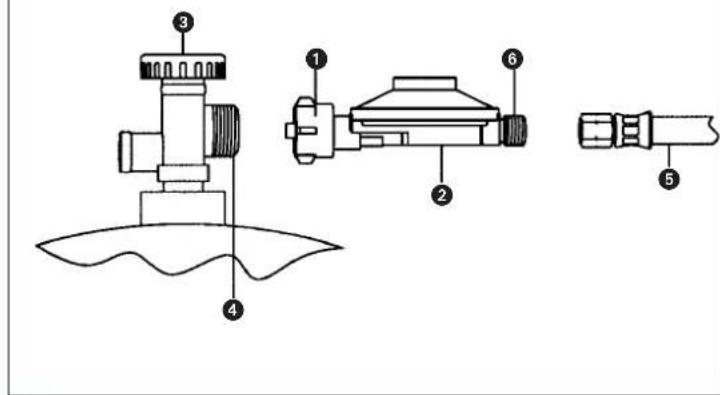
- Connect the union nut (1) of the pressure regulator (2) to the gas cylinder valve thread (4) by turning it counter-clockwise. Do not use tools – these could damage the gas cylinder valve gasket and leakage protection would no longer be guaranteed.
- Use an appropriate wrench size SW 17 and turn counter-clockwise to connect the hose line (5) to the pressure regulator output thread (6). When doing so, you must hold a second wrench of the correct size on the pressure regulator (faces are provided on the pressure regulator for this purpose) in order to stop the regulator being turned or too much force being transferred. Use the above tool to tighten the screw connection and to guarantee tightness and prevent leaks.
- Perform a leakage test on all connections with the gas cylinder valve (3) open. If there are no bubbles, the connection is tight and does not leak.
7. Starting up
- Open the gas cylinder valve (Fig. 2 / Item 3).
- Turn knob to the large flame symbol and press down completely. At the same time, activate the piezo ignition repeatedly. The regulating knob must be held down for approx. 10 more seconds after ignition until the burner remains on. If the flame extinguishes, do not repeat this procedure until at least 2 minutes have passed.
- Always turn the regulating knob slowly from the large flame symbol as far as the stop. The device may go off if the knob is turned too quickly.
- To turn off the device, close the bottle valve (3).
8. Taking out of operation
To turn off the heater, move the button to „closed" position and close the gas bottle valve.
9. Storage / Care / Repair
- Remove the pressure regulator with gas hose and check the gasket for damage. Please contact ISC GmbH in case of damage.
GB
● Never store the liquid gas cylinder inside the house, under ground or in non-ventilated areas!
● The party heater can be cleaned with all standard, non-abrasive and incombustible liquids.
- Be sure to turn off the heater and allow it to cool before commencing with the cleaning.
Caution! Never clean the heater with pressurized water (using a water hose, steam jet or high pressure)!
● Have only approved gas fitters carry out repairs and maintenance work on the party heater.
● Only original spare parts should be used for repairs.
● Maintenance: The hose must be checked for cracks or other damage every six months and should be replaced as needed. Every 2 years, the device should be subjected to a maintenance test by a specialized dealer. The gas hose must be checked every 5 years by a specialized dealer and should be replaced as needed. Pressure regulators should be replaced after five years, as rubber gaskets and diaphragms can become porous.
Rep.24 Routes 2 pces
F
13
F
1 platte open sleutel SW 8, SW 10, SW 14, SW 17
NL
NL
Pos.16 Stoppmutter M 8 2 st
Pos.17 Bricka DM 5,3 8 st
Pos.18 Bricka DM 6,4 9 st
Pos.19 Bricka DM 6,4 stor 1 st
Pos.20 Bricka DM 8,4 2 st
Pos.21 Hjul 2 st
3.2 PS 12 Niro
Pos.1 Reflektor 1 st
Pos.2 Brännare komplett 1 st
Pos.3 Adapterplát 1 st
Pos.4 Pelare 1 st
Pos.5 Platta
Pos.19 Stoppmutter M 8 2 st
Pos.20 Bricka DM 5,3 8 st
Pos.21 Bricka DM 6,4 9 st
Pos.22 Bricka DM 6,4 stor 1 st
Pos.23 Bricka DM 8,4 2 st
Pos.24 Hjul 2 st
Pos.25 Kantskyddband 360 1 st
Pos.26 Kantskyddband 245 3 st
Eschenstraße 6 - D-94405 Landau/Isar (Germany)
Info-Tel. 0180-5 120 509 • Telefax 0180-5 835 830
The product described in those instructions comes with a 2-year warranty covering defects. This 2-year warranty period begins with the passing of risk or when the customer receives the product.
For warranty claims to be accepted, the product has to receive the current maintenance and be put to the proper use as described in the operating instructions.
Your statutory rights of warranty are naturally unaffected during these 2 years.
This warranty applies in Germany, or in the respective country of the manufacturer's main regional sales partner, as a supplement to local regulations. Please note the details for contacting the customer service center responsible for your region or the service address listed below.
NL GARANTIE
The reprinting or reproduction by any other means, in whole or in part, of documentation and papers accompanying products is permitted only with the express consent of ISC GmbH.