
K4310 FXP - Drain cleaning machine RIDGID - Free user manual and instructions
Find the device manual for free K4310 FXP RIDGID in PDF.

| Product type | Drum drain cleaning machine |
| Brand | RIDGID |
| Model | K4310 FXP |
| Cleaning capacity | Pipes from 3" to 10" in diameter (75 to 250 mm) |
| Cable diameter | 5/8" (16 mm) or 3/4" (20 mm) |
| Maximum reach | 250' (76 m) depending on cable diameter |
| Drum capacity (5/8" cable) | 100' (30.5 m) |
| Drum capacity (3/4" cable) | 100' (30.5 m) |
| Power source | RIDGID FXPXX battery pack or FXP power adapter (54 V DC, 15 A) |
| Motor type | Brushless DC motor, 810 W |
| No-load speed | 230 rpm |
| Weight without cable (with 3/4" drum, pigtail and AUTOFEED) | 123 lbs (55.8 kg) |
| Weight with 100' of 3/4" cable and AUTOFEED | 237 lbs (107.5 kg) |
| Weight with 100' of 5/8" cable and AUTOFEED | 193 lbs (87.5 kg) |
| Dimensions (L x W x H) without AUTOFEED and handle folded | 34" x 22" x 35" (864 x 559 x 889 mm) |
| Dimensions (L x W x H) with AUTOFEED and handle deployed | 37" x 22" x 47" (940 x 559 x 1194 mm) |
| Key features | AUTOFEED system for cable advancement/retraction, pneumatic foot pedal, control panel with distance display, wireless connection via RIDGID Link app |
| Maintenance and cleaning | Clean after each job with a soft cloth and soapy water; rinse the drum, cable and AUTOFEED system; lubricate the grease fittings every 20 hours of use or after drum change |
| Safety | Built-in GFCI, RIDGID drain cleaning gloves required, maximum distance of 3' (90 cm) between cable outlet and pipe entry, automatic shut-off if tool jams |
| Spare parts and repairability | Replacement parts available: drums, cables, pigtails, cleaning tools, chargers, etc. Repairs must be carried out by an authorized RIDGID repair center |
| Warranty | Full Lifetime Warranty covering defects in materials and workmanship |
| Operating temperature | -4°F to 140°F (-20°C to 60°C) |
Frequently Asked Questions - K4310 FXP RIDGID
User questions about K4310 FXP RIDGID
0 question about this device. Answer the ones you know or ask your own.
Ask a new question about this device
Download the instructions for your Drain cleaning machine in PDF format for free! Find your manual K4310 FXP - RIDGID and take your electronic device back in hand. On this page are published all the documents necessary for the use of your device. K4310 FXP by RIDGID.
USER MANUAL K4310 FXP RIDGID
K-4310 FXP Drum Machine

natural_image
Ridgid electric vehicle charging station with visible branding and control panel (no text-heavy elements)

text_image
QR code image containing encoded data, no visible human-readable textRIDGID.com/qr/k4310
- Français- 27
- Castellano – 55
Table of Contents
Recording Form For Machine Serial Number....1
Safety Symbols 2
General Power Tool Safety Warnings
Work Area Safety 2
Electrical Safety 2
Personal Safety 3
Power Tool Use And Care 3
Battery Tool Use And Care 3
Service....4
Specific Safety Information
K-4310 FXP Drum Machine Safety 4
RIDGID Contact Information....5
Description....5
Specifications 8
Standard Equipment 8
Machine Assembly
Installing Cable 9
Installing AUTOFEED® Unit 9
Attaching Front Guide Hose (Optional Equipment for use with AUTOFEED Unit) 10
Advance Display And Control Panel
Setting Cable Information 10
Monitoring And Recording Drain Cleaning Information....10
Hibernation Mode 11
Pre-Operation Inspection
Machine and Work Area Set-Up 12
Installing/Removing Battery or Power Adapter 14
Operating Instructions
K-4310 FXP Drum Machine Operation 16
Advancing The Cable Into The Drain 16
Passing Through Traps Or Other Transitions 17
Cleaning The Drain 17
Working The Blockage 18
Handling A Stuck Tool....18
Freeing A Stuck Tool 18
Retrieving The Cable 18
RIDGID Link App Connection (Wireless Communication)....19
Other Operating Instructions
Using Machine With A Front Guide Hose....19
Adding Additional Cable....19
Changing Drums....20
Draining The Machine....20
Transportation And Storage
Transportation....21
Storage 21
Maintenance Instructions
Cleaning....21
Cleaning the Cable Travel Sensors....22
Lubrication 22
Changing Cable 22
Pigtail Replacement....22
Troubleshooting....23
Service And Repair 24
Optional Equipment 24
Disposal....25
FCC/ICES & Conformity ...... Inside Back Cover
Lifetime Warranty....Back Cover
*Original Instructions - English
Drum Machines
K-4310 FXP Drum Machine

natural_image
Two identical RIDGID industrial machines with wheels and control panels, shown from different angles (no visible text or symbols on the machines themselves)
WARNING!
Read this Operator's Manual carefully before using this tool. Failure to understand and follow the contents of this manual may result in electrical shock, fire and/or serious personal injury.
| K-4310 FXP Drum Machine | |
| Record Serial Number below and retain product serial number which is located on nameplate. | |
| Serial No. | |
Safety Symbols
In this operator's manual and on the product, safety symbols and signal words are used to communicate important safety information. This section is provided to improve understanding of these signal words and symbols.

This is the safety alert symbol. It is used to alert you to potential personal injury hazards. Obey all safety messages that follow this symbol to avoid possible injury or death.
DANGER
DANGER indicates a hazardous situation which, if not avoided, will result in death or serious injury.
WARNING
WARNING indicates a hazardous situation which, if not avoided, could result in death or serious injury.
CAUTION
CAUTION indicates a hazardous situation which, if not avoided, could result in minor or moderate injury.
NOTICE
NOTICE indicates information that relates to the protection of property.

This symbol means read the operator's manual carefully before using the equipment. The operator's manual contains important information on the safe and proper on of the equipment.

This symbol means always wear safety glasses with side shields or goggles when handling or using this equipment to reduce the risk of eye injury.

This symbol indicates to keep the machine cable outlet within 3' (0.9 M) of the drain inlet to better control cable and risk of cable twisting, kinking or breaking. Read for more information.

This symbol indicates that RIDGID RBC-FXPXX series batteries can be used with this tool.

This symbol indicates the risk of hands, fingers or other body parts being caught, wrapped or crushed in the drain cleaning cable.

This symbol means always wear RIDGID drain cleaning gloves when handling or using this equipment to reduce the risk of injury.

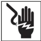
This symbol indicates the risk the electrical shock.

This is information symbol and indicates the product information available (including operators' manual) by scanning the adjacent QR code.

This symbol indicates that the marked equipment exceeds 55 lbs. (25kg). Exercise caution when lifting or moving to reduce the risk of injury.
General Power Tool Safety Warnings\*
WARNING
Read all safety warnings, instructions, illustrations and specifications provided with this power tool. Failure to follow all instructions listed below may result in electric shock, fire and/or serious injury.
SAVE ALL WARNINGS AND INSTRUCTIONS FOR FUTURE REFERENCE!
The term "power tool" in the warnings refers to your mains-operated (corded) power tool or battery-operated (cordless) power tool.
Work Area Safety
- Keep work area clean and well lit. Cluttered or dark areas invite accidents.
- Do not operate power tools in explosive atmospheres, such as in the presence of flammable liquids, gases, or dust. Power tools create sparks which may ignite the dust or fumes.
- Keep children and bystanders away while operating a power tool. Distractions can cause you to lose control.
Electrical Safety
- Power tool plugs must match the outlet. Never mod ify the plug in any way. Do not use any adapter plugs with earthed (grounded) power tools. Unmodi fied plugs and matching outlets will reduce risk of electric shock.
- Avoid body contact with earthed or grounded surfaces such as pipes, radiators, ranges and refrigerators. There is an increased risk of electrical shock if your body is earthed or grounded.
- Do not expose power tools to rain or wet conditions. Water entering a power tool will increase the risk of electrical shock.
-
Do not abuse the cord. Never use the cord for carrying, pulling or unplugging the power tool. Keep cord away from heat, oil, sharp edges or moving parts. Damaged or entangled cords increase the risk of electric shock.
-
When operating a power tool outdoors, use an extension cord suitable for outdoor use. Use of a cord suitable for outdoor use reduces the risk of electric shock.
- If operating a power tool in a damp location is unavoidable, use a ground fault circuit interrupter (GFCI) protected supply. Use of a GFCI reduces the risk of electric shock.
Personal Safety
- Stay alert, watch what you are doing and use common sense when operating a power tool. Do not use a power tool while you are tired or under the influence of drugs, alcohol, or medication. A moment of inattention while operating power tools may result in serious personal injury.
- Use personal protective equipment. Always wear eye protection. Protective equipment such as dust mask, non-skid safety shoes, hard hat, or hearing protection used for appropriate conditions will reduce personal injuries.
- Prevent unintentional starting. Ensure the switch is in the OFF-position before connecting to power source and/or battery pack, picking up or carrying the tool. Carrying power tools with your finger on the switch or energizing power tools that have the switch ON invites accidents.
- Remove any adjusting key or wrench before turning the power tool ON. A wrench or a key left attached to a rotating part of the power tool may result in personal injury.
- Do not overreach. Keep proper footing and balance at all times. This enables better control of the power tool in unexpected situations.
- Dress properly. Do not wear loose clothing or jewelry. Keep your hair, and clothing away from moving parts. Loose clothes, jewelry, or long hair can be caught in moving parts.
- If devices are provided for the connection of dust extraction and collection facilities, ensure these are connected and properly used. Use of dust collection can reduce dust-related hazards.
- Do not let familiarity gained from frequent use of tools allow you to become complacent and ignore tool safety principles. A careless action can cause severe injury within a fraction of a second.
Power Tool Use and Care
- Do not force power tool. Use the correct power tool
for your application. The correct power tool will do the job better and safer at the rate for which it is designed.
- Do not use power tool if the switch does not turn it ON and OFF. Any power tool that cannot be controlled with the switch is dangerous and must be repaired.
- Disconnect the plug from the power source and/or the battery pack, if detachable, from the power tool before making any adjustments, changing accessories, or storing power tools. Such preventive safety measures reduce the risk of starting the power tool accidentally.
- Store idle power tools out of the reach of children and do not allow persons unfamiliar with the power tool or these instructions to operate the tool. Power tools are dangerous in the hands of untrained users.
- Maintain power tools and accessories. Check for misalignment or binding of moving parts, breakage of parts and any other condition that may affect the power tool's operation. If damaged, have the power tool repaired before use. Many accidents are caused by poorly maintained power tools.
- Keep cutting tools sharp and clean. Properly maintained cutting tools with sharp cutting edges are less likely to bind and are easier to control.
- Keep handles and grasping surfaces dry, clean and free from oil and grease. Slippery handles and grasping surfaces do not allow for safe handling and control of the tool in unexpected situations.
- Use the power tool, accessories and tool bits etc. in accordance with these instructions, taking into account the working conditions and the work to be performed. The use of the power tool for operations different from those intended could result in a hazardous situation.
Battery Tool Use And Care
- Recharge only with the charger specified by the manufacturer. A charger that is suitable for one type of battery pack may create a risk of fire when used with another battery pack.
- Use power tools only with specifically designated battery packs. Use of any other battery packs may create a risk of injury and fire.
-
When battery pack is not in use, keep it away from other metal objects, like paper clips, coins, keys, nails, screws or other small metal objects that can make a connection from one terminal to another. Shorting the battery terminals together may cause burns or a fire.
-
Under abusive conditions, liquid may be ejected from the battery; avoid contact. If contact accidentally occurs, flush with water. If liquid contacts eyes, additionally seek medical help. Liquid ejected from the battery may cause irritation or burns.
- Do not use a battery pack or tool that is damaged or modified. Damaged or modified batteries may exhibit unpredictable behavior resulting in fire, explosion or risk of injury.
- Do not expose a battery pack or tool to fire or excessive temperature. Exposure to fire or temperature above 265 °F (130 °C) may cause explosion.
- Follow all charging instructions and do not charge the battery pack or tool outside the temperature range specified in the instructions. Charging improperly or at temperatures outside the specified range may damage the battery and increase the risk of fire.
Service
- Have your power tool serviced by a qualified repair person using only identical replacement parts. This will ensure that the safety of the power tool is maintained.
- Never service damaged battery packs. Service of battery packs should only be performed by the manufacturer or authorized service providers.
Specific Safety Information
WARNING
This section contains important safety information that is specific to this tool.
Read these precautions carefully before using the K-4310 FXP Drum Machine to reduce the risk of electrical shock or other serious personal injury.
SAVE THESE INSTRUCTIONS!
Keep this manual with machine for use by the operator.
K-4310 FXP Drum Machine Safety
- Before using the tool, test the ground fault circuit interrupter (GFCI) provided with the supply cord to ensure it is operating correctly. A properly operating GFCI reduces the risk of electrical shock.
- Only use extension cords that are protected by a GFCI. The GFCI on the machine power cord will not prevent electrical shock from extension cords.
-
Only grasp the rotating cable with gloves recommended by the manufacturer. Latex or loose fitting gloves or rags can become wrapped around the cable and may result in serious personal injury.
-
Do not allow the cutter to stop turning while the cable is turning. This can overstress the cable and may cause twisting, kinking or breaking of the cable and may result in serious personal injury.
- One person must control both the cable and switch. If the cutter stops rotating, the operator must be able to turn the tool off to prevent the cable from twisting, kinking and breaking.
- Use latex or rubber gloves inside the gloves recommended by the manufacturer, goggles, face shields, protective clothing, and respirator when chemicals, bacteria or other toxic or infectious substances are suspected to be in a drain line. Drains may contain chemicals, bacteria and other substances that may cause burns, be toxic or infectious or may result in other serious personal injury.
- Practice good hygiene. Do not eat or smoke while handling or operating the tool. After handling or operating drain cleaning equipment, use hot, soapy water to wash hands and other body parts exposed to drain contents. This will help reduce the risk of health hazards due to exposure to toxic or infectious material.
- Only use the drain cleaner for the recommended drain sizes. Using the wrong size drain cleaner can lead to twisting, kinking or breaking of the cable and may result in personal injury.
- Keep hands away from rotating drum. Do not reach into drum unless battery or adapter is removed. Hand may be caught in the moving parts.
- Keep glove-covered hand on the cable whenever the machine is running. This provides better control of the cable and helps prevent twisting, kinking and breaking of the cable that may result in serious personal injury.
- Position machine cable outlet within 3' (0.9 m) of the drain inlet or properly support exposed cable when the distance exceeds 3' (0.9 m). Greater distances can cause control problems leading to twisting, kinking or breaking of the cable. Twisting, kinking or breaking cable may cause striking or crushing injuries.
- Do not operate with cable end outside of drain. Rotating cable end can whip, strike, catch or cut. Insert cable at least 12" (0.3m) into drain before starting machine.
- Do not operate the machine in REV (reverse) rotation except as described in this manual. Operating in reverse can result in cable damage and is used to back (unscrew) the cable end out of blockages.
- Cable is a spring that stores energy if stuck, stretched or twisted, including flipped in drum. Even if the machine is "OFF", this stored energy can cause the cable to unexpectedly move, twist or kink and cause injury. Exercise caution around cables in these situations to reduce the risk of injury.
- Do not wear loose clothing or jewelry. Keep your hair and clothing away from moving parts. Loose clothing, jewelry or hair can be caught in moving parts.
- Do not operate this machine if operator or machine is standing in water. Operating machine while in water increases the risk of electrical shock.
- Do not let the use or monitoring of the control panel distract you from controlling the cable and drain cleaning process. Inattention to the cable and process can cause you to lose control and increases the risk of serious injury.
- Do not use if there is the risk of contact with other utilities (such as natural gas or electric) during operation. Visual inspection of the drain with a camera is a good practice. Cross bores, improperly placed utilities and damaged drains could allow the cutter to contact and damage the utility. This could cause electrical shock, gas leaks, fire, explosion or other serious damage or injury.
- Before operating a RIDGID® K-4310 FXP Drum Machine, read and understand:
- This operator's manual
- The FXP Battery/Charger manual
- The FXP Power Adapter manual
- The instructions for any other equipment or material used with this tool.
Failure to follow all instructions and warnings may result in property damage and/or serious injury.
RIDGID Contact Information
If you have any question concerning this RIDGID® product:
- Contact your local RIDGID® distrib utor.
- Visit RIDGID.com to find your local RIDGID contact point.
- Contact Ridge Tool Technical Service Department at ProToolsTechService@Emerson.com, or in the U.S. and Cana da call 844-789-8665.
Description
The RIDGID ^® K-4310 FXP Drum Machine is designed to clean various size and length drain lines depending on size of cable being used. Applications may include floor drains, laterals, main lines and commercial lines.
The K-4310 FXP can be used with 58 " and 34 " diameter cable to clean 3" to 10" drains (see specifications). All cables are equipped with a quick-change coupling system for connecting and disconnecting tools.
The K-4310 FXP Drum Machine is powered by the FXP Battery or FXP Power Adapter. The main ON/OFF switch controls power to the machine and to the FOR/OFF/REV switch which controls the motor, drum and cable rotation. A pneumatic foot switch acts as a momentary contact ON/OFF switch controlling the operation of the motor.
The machine is equipped with an AUTOFEED® Cable Feed Unit that will advance or retrieve the cable. The AUTOFEED unit includes a feature to quickly change between cable sizes. The machine can also be used by manually advancing and retrieving the cable.
The machine is supplied with an advanced display and control panel to allow cable information to be entered, show real time cable travel in and out of the drum and record job information. The K-4310 FXP Drum Machine includes wireless technology to allow connection to smart phones and tablets and allow for shareable job insights and tool history data lookup. See "RIDGID Link App connection (Wireless Communication)" section for details.
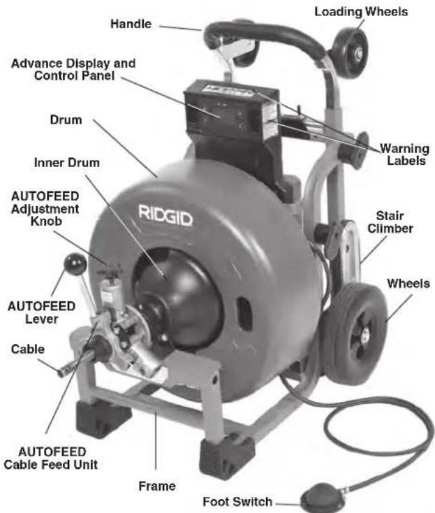
text_image
Handle Loading Wheels Advance Display and Control Panel Drum Inner Drum AUTOFEED Adjustment Knob RIDGID Warning Labels Stair Climber Wheels AUTOFEED Lever Cable AUTOFEED Cable Feed Unit Frame Foot SwitchFigure 1A – RIDGID K-4310 FXP Drum Machine
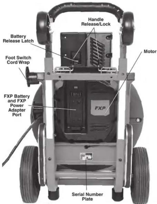
text_image
Handle Release/Lock Battery Release Latch Foot Switch Cord Wrap Motor FXP Battery and FXP Power Adapter Port Serial Number PlateFigure 1B - RIDGID K-4310 FXP Drum Machine

text_image
FOR FORWARD ROTATION Record Button Motor FOR/OFF/REV Switch Power ON/OFF Switch Cable Length Selector Button Cable Travel Reset (Zero) Button Cable Diameter Selector ButtonFigure 2A – Advance Display and Control Panel
| Icon | Control Primary Function/Short | Press | Alternate Function/Long Press (+2 sec) |
| Cable Travel Reset (Zero) Button | Reset Cable Distance to Zero None | ||
| Cable Diameter Selector Button | Set Cable Diameter from available range | None | |
| Cable Length Selector Button Set | Cable Length from available range None | ||
| Record Button Start or Stop Recording | Toggle Metric/Imperial Units |
Figure 2B – Controls Chart

text_image
Tool Status Lights Recording/Time of Recording 0'00" Cable Travel Indication ft/m Cable Length Selector Cable Size Selection Recording Active, Selections LockedFigure 3 – Display/Icons
| ON/OFF Switch | FOR/OFF/REV Switch | Foot Switch | Display | Tool Status Lights | Description |
| OFF Any Position Any Position OFF OFF | Machine OFF – No power to | anything | |||
| ON | Any Position | OFF | ON | ONSee Figure 5 | Machine Motor OFF, Power to Display – Display settings can be changed, see Figure 2A/B |
| ON | Any Position | OFF | OFF | OFF | Machine in Hibernation Mode to reduce battery usage. Machine will go to this mode if no user inputs for 15 minutes or more – Move ON/OFF switch to OFF and back to ON to use |
| ON | FOR | ON | ON | See Figure 5 | Machine will run in Forward rotation when Foot Switch is depressed (normal operating mode, generally used for all drain cleaning, both advancing and retrieving cable) |
| ON | REV | ON | ON | See Figure 5 | Machine will run in Reverse rotation when Foot Switch is depressed (Only used for specific cases called out in the manual) |
Figure 4 – Machine Operation Modes
| Icon Blinking Light Solid Light Meaning | |||
 | Blue Connection to RIDGID | Link app possible. | |
| Blue (30s) Connection to RIDGID Link app established. | |||
 | Yellow | Battery charge is low and machine operation can stop anytime soon. Battery must be recharged. | |
| Yellow Red | Battery low and machine will not operate. Recharge battery/insert fully charged battery. | ||
| Yellow Maintenance is required. Consult RIDGID Link app for more information. | |||
| Red | Machine has stopped due to an event exceeding usable limits (e.g., current, temperature, or stability). Confirm proper set-up and restart use. Consult RIDGID Link app for more information. | ||
| Red | Machine has malfunctioned and will not operate. Remove battery and allow Machine to rest, then reinsert battery. If light still ON, have machine serviced. Consult RIDGID Link app for more information. | ||
| Purple | Firmware update in process, machine cannot be used while updating. Consult RIDGID Link app for more information. | ||
| Purple Red | Firmware update was interrupted and not completed; machine cannot be used. Continue and complete update per app instructions. | ||
Figure 5 – Tool Status Lights

text_image
RIDGE Tool Company, Elyria, Ohio, U.S.A. RIDGID.com Model No. Serial No. XXXXXMMYY V### V n0 /min InterbelcFigure 6 – Machine Serial Number - The last 4 digits of the serial number indicate the month and year of the manufacture
Specifications
Drain Line
Capacity ......See Following Chart
| Cable Size | Line Size Maximum Reach | Maximum AUTO-FEED Unit Speed |
| 5/8" (16mm) | 3" to 6" (75 mm to 150 mm) | 250' (76m) 25'/Min (7.6 m/min) |
| 3/4" (20mm) | 4" to 10" (100 mm to 250 mm) | 250' (76m) 28'/Min (8.5 m/min) |
See RIDGID catalog for information on specific cables available.
Drain
Capacity ......3" to 10" (75mm to 250mm)
Drum Capacity,
5/8" Drum...... 100' (30.5m) of ^5/_8 " (16mm) Diameter Cable
Drum Capacity,
3/4" Drum...... 125' (38.1m) of ^5/_8 " (16mm) Diameter Cable
125' (38.1m) of Cable ^11/16 " (17.5mm) Diameter
100' (30.5m) of 34 " (20mm) Diameter Cable
Power Supply ....RIDGID RB-FXPXX Battery Pack OR FXP Power Adapter (See Optional Equipment Section)
Motor Type......Brushless DC
Watts 810 W
Voltage .....54V DC nominal
Amps....15 A
No Load Output
Speed.....230 RPM
Controls....Main ON-OFF Switch, FOR/OFF/REV Switch, Pneumatic Foot Switch, AUTOFEED® Cable Feed Unit Lever
Operating
Temperature.....-4° F to 140° F (-20° C to 60° C)
Storage
Temperature.....-4° F to 140° F (-20° C to 60° C)
Wireless Connection
Range....33 ft (10 m)
Memory ....50 Job Recordings (1 Job is approximately 2 hours)
Cable Travel
Tolerance.....+/- 3 ft (+/- 0.9 m)**
Frame Type .....Wheeled Cart
Weight (No Cable, 3/4" Drum w/pigtail and AUTOFEED
Unit)....123 lbs. (55.8 kg)
Weight (w/100' of 3/4" Cable and AUTOFEED
Unit)....237 lbs. (107.5 kg)
Weight (w/100' of 5/8" Cable and AUTOFEED
Unit)....193 lbs. (87.5 kg)
Dimension LxWxH (no AUTOFEED Unit, Handle
down)....34" x 22" x 35"
(864mm × 559mm × 889mm)
Dimension LxWxH (w/AUTOFEED Unit, Handle
up) 37" x 22" x 47"
(940mm x 559mm x 1194mm)
Sound Pressure
(L_PA)^* 84.5 dB(A), K=3
Sound Power
(L_WA)^* 85.09 dB(A), K=3
* Sound measurements are measured in accordance with a standardized test per Standard EN 62481-1.
- Sound emissions may vary due to your location and specific use of these tools. - Daily exposure levels for sound need to be evaluated for each application and appropriate safety measures taken when needed. Evaluation of exposure levels should consider the time a tool is switched off and not in use. This may significantly reduce the exposure level over the total working period.
** Cable Travel Tolerance – this tolerance assumes that the correct cable parameters are entered (cable diameter, cable length and drum) and that the full cable length is in the drum (the cable end is no more than 6" (150 mm) out of the end of the AUTOFEED cable feed unit) when the cable travel is zeroed. Incorrect cable parameters and zeroing the cable travel with cable out of the drum results in a greater cable travel tolerance, in some cases up to +/- 8 ft (+/-2.5m). Cable travel does not necessarily equal distance the cable end has traveled in the drain.
All specifications are nominal and may change as design improvements occur.
Standard Equipment
All K-4310 FXP Drum Machines comes with one pair of RIDGID Drain Cleaning Gloves. Refer to the RIDGID catalog for details on equipment supplied with specific machine catalog numbers.
NOTICE This machine is made to clean drains. If properly used it will not damage a drain that is in good condition and properly designed, constructed and maintained. If the drain is in poor condition, or has not been properly
designed, constructed and maintained, the drain cleaning process may not be effective or could cause damage to the drain. The best way to determine the condition of a drain before cleaning is through visual inspection with a camera. Improper use of this machine can damage the machine and the drain. This machine may not clear all blockages.
Machine Assembly
WARNING
To reduce the risk of serious injury during use, follow these procedures for proper assembly. The ON/OFF switch should be OFF and battery removed/ power adapter unplugged.
Installing Cable
Do not remove cable carton straps from carton. The cable is under tension and can whip or strike if released. When changing cable size, the AUTOFEED® unit settings and the advance display and control panel settings need to be changed.
Manual Cable Installation
- Retrieve male coupling end of cable through the center hole of carton and pull approximately 6' of cable from carton.
- Connect male coupling of cable to the pigtail coupling as shown in Figure 15. Confirm connection is secure.
- Pull short sections of cable from the carton and manually feed into the drum. Do not turn machine ON.
Cable Installation with AUTOFEED unit
- Retrieve male coupling end of cable through center hole of carton and pull cable from carton. Lay cable out straight in a flat area (such as an empty paved parking lot or driveway) with no obstructions or items that could become wrapped around the cable.
- When using AUTOFEED unit to load cable, the rotating cable will tend to walk sideways. To prevent this, place suitable stops (such as wood blocks) on either side of the cable at 10-foot intervals.
- After properly inspecting and setting up the drain cleaning machine, attach cable to the pigtail as shown in Figure 15. Make sure that no one is in the area around cable. Operate the machine/AUTOFEED unit per the operating instructions to retrieve the cable into the drum. When 10' of cable is left outside of the drum, step off the foot switch and move the main ON/OFF switch to OFF. Loosen the AUTOFEED knob and manually feed the remaining cable into the drum. Do not use the AUTOFEED unit
to put entire cable in the drum. The cable end can whip around and cause serious injury.
Installing AUTOFEED® Unit
- Loosen the AUTOFEED knob to allow the cable to pass through AUTOFEED unit.
- Pull approximately 12" of cable from the drum.
- Place AUTOFEED unit over the cable and align the posts with mating holes in the AUTOFEED mount (Figure 7).
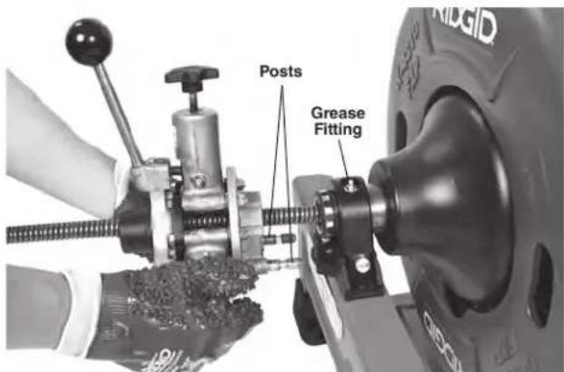
text_image
Posts Grease FittingFigure 7 – Installing the AUTOFEED Unit
- Fully insert posts into frame holes. Confirm secured in place.
Removing AUTOFEED Unit
- Pull the plunger pin and open the drum retainer (Figure 8).
- Loosen AUTOFEED knob to allow cable to pass through unit.
- Pull the AUTOFEED unit straight forward to disengage the pins from the frame.
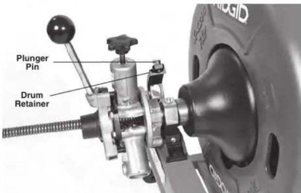
text_image
Plunger Pin Drum RetainerFigure 8 – Opening Drum Retainer
Adjusting AUTOFEED Unit For Cable Diameter
For proper operation, the AUTOFEED unit must be adjusted to the correct setting for the cable it is being used with. The setting of the unit can be checked by looking at the front of the unit, see Figure 9. The slot aligns with the cable size.
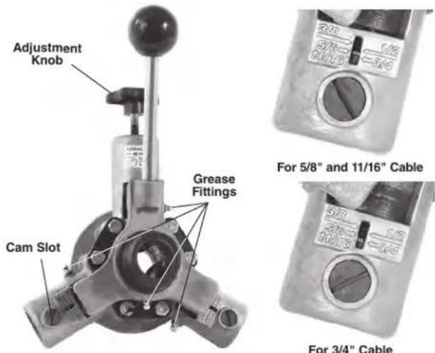
text_image
Adjustment Knob Cam Slot Grease Fittings For 5/8" and 11/16" Cable 3/8" 3/10" 3/12" 3/14" For 3/4" CableFigure 9 – Checking AUTOFEED Unit Setting
To change setting between 5 / 8'' and 3 / 4'' .
-
Loosen the AUTOFEED adjustment knob.
-
Use a flat blade screwdriver in cam slot to rotate both cams (see Figure 9). If using ^11/16 " cable, use the ^5/8 " setting.
Attaching Front Guide Hose (Optional Equipment for use with AUTOFEED Unit)
-
Pull approximately 4' of cable from the drum.
-
Slide Front Guide Hose over the cable, adapter end first.
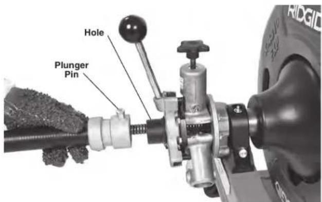
text_image
Hole Plunger PinFigure 10 – Attaching Front Guide Hose
- Pull plunger pin head up and place adapter over the
mounting collar on the AUTOFEED unit. Make sure plunger pin locks into the hole in the mounting collar. (Figure 10).
Advance Display And Control Panel
Setting Cable Information
The K-4310 FXP Drum Machine is equipped to monitor and display the cable travel in and out of the drum.
To work properly, cable/drum information must be entered using the control panel (or RIDGID Link App, if connected).
- Move the main ON/OFF switch to ON position.
- Toggle Between cable size selection using Cable Diameter Selector Button (see Figure 2/3). When selected, the screen will return to home screen after 3 seconds.
- Toggle between cable length selection using Cable Length Selector Button (see Figure 2/3). When selected, the screen will return to home screen after 3 seconds.
- Move the main ON/OFF switch to OFF position.
NOTE: These settings will be saved and will not need updated unless a different drum/cable is used. This feature does not work with cables not listed on the display. Incorrect cable information will decrease the cable travel accuracy.

text_image
5/8"a. Cable Diameter Screen

text_image
50°b. Cable Length Screen
Figure 11 – Setting Cable Parameters
Monitoring And Recording Drain Cleaning Information
The advance display and control panel allows monitoring of the cable travel in and out of the drum. The zero point is set by depressing the cable travel reset "Zero" button. See Figure 2. For best results the calibration should be performed with no more than 6" (150 mm) of cable outside the drum. Remember that cable travel is always relative to the zero point. If the cable is reset with more than 6" (150 mm) out of the drum the cable travel reading may be off by more than +/-3 ft. (+/- 0.9 m).
Confirm that the cable information on the Control Panel matches the cable being used. Incorrect cable information can affect the accuracy of the travel readings. Do not
let the use or monitoring of the control panel distract you from controlling the cable and drain cleaning process. Inattention to the cable and drain cleaning process can cause you to lose control and increases the risk of serious injury.
The Record button is used to start and stop recording. Recording will also stop when ON/OFF switch is moved to OFF position.
Recorded information includes cable travel and motor amp draw information versus time. The K-4310 FXP Drum Machine will hold 50 recordings. When 50 recordings are reached, new recordings will overwrite the oldest recordings. Additional recordings can be stored via the RIDGID Link App. Recorded information can be accessed and managed through the RIDGID Link App - see the RIDGID Link App Connection (Wireless Communication) section for further information.
Hibernation Mode
When running on battery power, if the ON/OFF switch is ON and the machine is not used for 15 minutes, it will move into "Hibernation Mode" to conserve battery charge. In Hibernation Mode, the display and tool status lights will turn off and the machine cannot be used until the ON/OFF switch is cycled OFF and back ON. See Figure 4.
If a Job Recording is active while the machine is in Hibernation Mode, the in-progress recording will be saved. When the machine is turned back ON, a new recording will need to be started.
Pre-Operation Inspection
WARNING


Before each use, inspect your K-4310 FXP Drum Machine and correct any problems to reduce the risk of serious injury from electric shock, twisted or broken cables, chemical burns, infections and other causes and prevent machine damage.
Always wear safety glasses, RIDGID drain cleaning gloves, and other appropriate protective equipment when inspecting your machine.
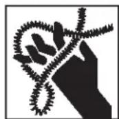
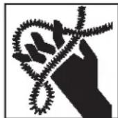
- Inspect the RIDGID drain cleaning gloves or mitts ("gloves") (Figure 12). Make sure they are in good condition with no holes, tears or loose sections that could be caught in the rotating cable. It is important not to wear improper or damaged gloves. The gloves protect your hands from the rotating cable. If the
gloves are not RIDGID drain cleaning gloves or are damaged or worn out, do not use machine until RIDGID drain cleaning gloves are available. Wear latex or rubber glove inside the RIDGID drain cleaning gloves to protect against drain contents.

natural_image
Pair of white industrial gloves with visible wear and branding (no readable text or symbols)
natural_image
Pair of textured, dark material gloves with no visible text or symbols on the gloves themselves.Figure 12 – RIDGID Drain Cleaning Gloves – Leather, PVC
- Make sure that the main ON/OFF switch is set to the OFF position and remove battery/power adapter.
- Clean the drain cleaning machine, including handles and controls. This aids inspection and helps prevent the machine or control from slipping from your grip. Clean and maintain the machine per the maintenance instructions.
-
Inspect the machine for the following:
-
Proper assembly, maintenance and completeness.
- Any broken, worn, missing, misaligned or binding parts.
- Rotate the drum and make sure that it turns freely without binding.
- Smooth and free movement of the AUTOFEED lever throughout range.
• Presence and readability of warning labels (Figure1). -
Any other condition which may prevent safe and normal operation.
If any problems are found, do not use the drain cleaning machine until the problems have been repaired. -
Clean any debris from the cable and cutting tools. Inspect cables for wear and damage. Inspect for:
-
Obvious flats worn into the outside of cable (cable is made from round wire and the profile should be round).
- Multiple or excessively large kinks (slight kinks up to 15 degrees can be straightened).
- Space between cable coils indicating that the cable has been deformed by stretching, kinking, or running in reverse (REV).
- Excessive corrosion from storing wet or exposure to drain chemicals.
All these forms of wear and damage weaken the cable and make cable twisting, kinking or breaking
more likely during use. Replace worn and damaged cable before using drain cleaning machine.
Inspect the cable couplings for wear and damage. Confirm that coupling plunger pins move freely and fully extend for positive retention. If needed, lubricate with a light oil.
Make sure the cable is fully retracted with no more than 6" (150mm) of cable outside of the machine. This will prevent whipping of the cable at start up.
- Inspect the tools for wear and damage. If necessary, replace prior to using the machine. Dull or damaged cutting tools can lead to binding, cable breakage, and slow the drain cleaning process.
- Inspect and maintain any other equipment being used per its instructions to make sure it is functioning properly.
- Make sure that the main ON/OFF switch is set to the OFF position.
- Following the Machine and Work Area Set-Up, install a fully charged battery or power adapter into machine. If using the power adapter, confirm that the GFCI works correctly.
- Following the Operating Instructions, check the machine for proper operation. No more than 6" (150 mm) of cable should be out of the machine.
- Turn the main ON/OFF switch to the ON position and move the FOR/OFF/REV switch into the FOR position. Press and release the foot switch and note the direction of rotation of the drum. Let drum come to complete stop. If the foot switch does not control the machine operation, do not use the machine until the foot switch has been repaired. The drum should rotate counter-clockwise when viewed from the front of the drum and will match the drum direction shown on the drum in Figure 19.
- Place the FOR/OFF/REV switch into the REV position and repeat above testing to confirm that the drain cleaning machine operates properly in reverse. If the rotation is not correct, do not use the machine until it has been repaired.
- With the inspection complete, move the FOR/OFF/REV switch into the OFF position and turn the main ON/OFF switch to the OFF position. With dry hands remove battery/power adapter from the machine.
Machine and Work Area Set-Up
WARNING

Set up the K-4310 FXP Drum Machine and work area according to these procedures to reduce the risk of injury from electric shock, fire, machine tipping, twisted or broken cables, chemical burns, infections and other causes, and prevent machine damage.
Always wear safety glasses and other appropriate protective equipment when setting up your drain cleaning machine.
- Check for an appropriate work area. Operate in a clear, level, stable, dry, well-lit location. Do not use the drain cleaning machine while standing in water.
- Inspect the drain to be cleaned. If possible, determine the access point(s) to the drain, the size(s) and length(s) of the drain, distance to tanks or mainlines, the nature of the blockage, presence of drain cleaning chemicals or other chemicals, etc.
If chemicals are present in the drain, it is important to understand the specific safety measures required to work around those chemicals. Contact the chemical manufacturer for required information.
Confirm no other utilities are present in the drain or area to reduce the risk of damage. Visual inspection of the drain with a camera is a good practice.
If needed, remove fixture (water closet, etc.) to allow access to the drain. Do not feed the cable through a fixture. This could damage the cable and the fixture
- Determine the correct equipment for the application. See Specifications. Drain Cleaning Machines for other applications can be found by consulting the Ridge Tool Catalog, online at RIDGID.com.
Inner-Core Cable is not recommended for use through P-Traps and severe bends in lines smaller than 4". Optional 24" flexible trap leaders can be added to aid users through traps and tight clean-outs. - Make sure all equipment has been properly inspected.
-
If machine is equipped with an AUTOFEED unit, confirm that it is set to proper size for the cable being used (see Figure 9).
-
If needed, place protective covers in the work area. The drain cleaning process can be messy.
-
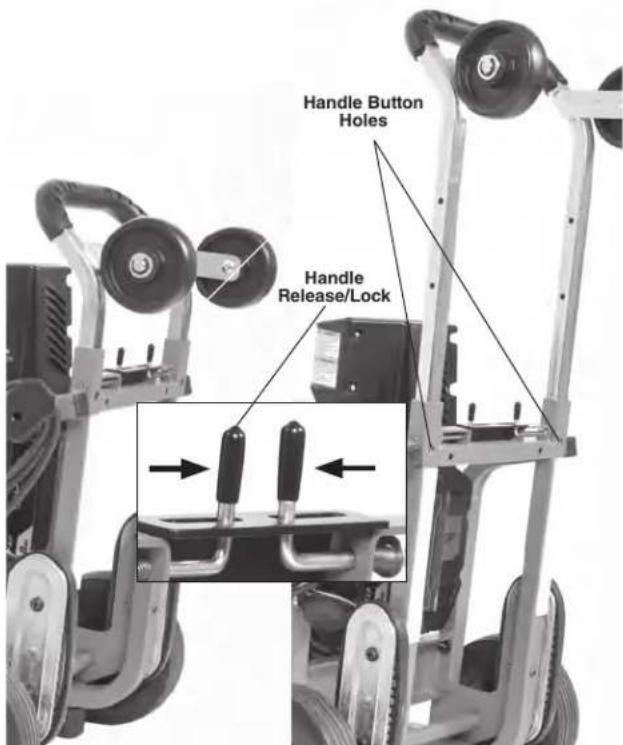
Transport the drain cleaning machine to the work area along a clear path. Adjust handle if necessary (Figure 13). Move handle latches together and move telescoping handle to desired position. Confirm that the handle latches engage and the handle is securely held in position. If handle is moved past latch holes, the handle buttons will prevent the handle from pulling out. If this occurs, depress buttons to move handle.
text_image
Handle Button Holes Handle Release/LockFigure 13 – Adjusting Telescoping Handle
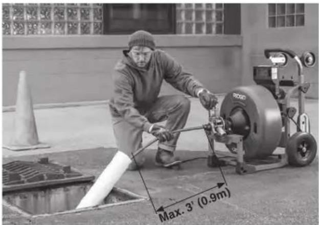
- Position the machine so it sits squarely and firmly. The machine cable outlet must be within 3' (0.9 m) of the drain access.
Greater distances from the drain access increases the risk of cable twisting or kinking. If the machine cannot be placed within proper distance of the drain access, extend the drain access with similar sized pipe and fittings (See Figure 14). Improper cable support can allow the cable to kink and twist and can damage the cable or injure the operator.
text_image
Max. 3' (0.9m)Figure 14 – Example of Extending Drain to within 3' of the Machine Cable Outlet
- Select proper cutting tool for the conditions.
If the nature of the obstruction is unknown, it is good practice to use a straight or bulb auger to explore the obstruction and retrieve a piece of the obstruction for inspection.
Once the nature of the obstruction is known, an appropriate tool can be selected for the application. A good rule of thumb is to start by running the smallest available tool through the blockage to allow the water to start flowing and carry away the debris and cuttings as the drain is cleaned. Once the drain is open and flowing, other tools appropriate for the blockage can be used. Generally, the largest tool used should be no bigger than the inside diameter of the drain minus one inch.
Proper tool selection depends on the specific circumstances of each job and is left to the user's judgment. A variety of other cable attachments are available and are listed in the "Optional Equipment" section of this manual. Other information on cable attachments can be found in the RIDGID Catalog and online at RIDGID.com.
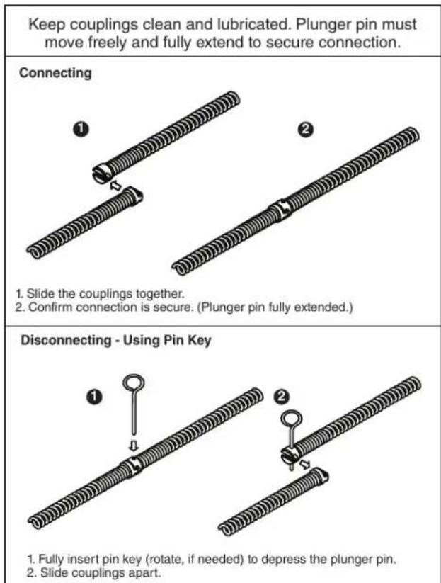
- Securely install cutting tool on the end of the cable (See Figure 15). If the connection is not secure, the tool may fall off during use. As the tool is installed, make sure that the spring-loaded plunger in the coupling moves freely to retain the tool. If the pin sticks in the retracted position, the tool may fall off in use.
text_image
Keep couplings clean and lubricated. Plunger pin must move freely and fully extend to secure connection. Connecting 1. Slide the couplings together. 2. Confirm connection is secure. (Plunger pin fully extended.) Disconnecting - Using Pin Key 1. Fully insert pin key (rotate, if needed) to depress the plunger pin. 2. Slide couplings apart.Figure 15 – Connecting/Disconnecting Cable/Tool
- Evaluate the work area and determine if any barriers are needed to keep bystanders away from the machine and work area. The drain cleaning process can be messy and bystanders can distract the operator.
- Position the foot switch for easy accessibility. You must be able to hold and control the cable, control the foot switch, and reach the FOR/OFF/REV switch.
- Confirm that the FOR/OFF/REV switch is in the OFF position and that the main ON/OFF switch is OFF.
Installing/Removing Battery or Power Adapter
- With dry hands, insert a fully charged battery or power adapter into the battery port on the machine. Do not plug power adapter in until inserted into the machine.
The machine has a latch to secure the battery or power adapter. The latch will engage when the battery or power adapter is inserted. Confirm secure by lightly pulling on the battery and ensure that it does not separate from the tool.
To remove the battery or power adapter, depress the latch and slide out of the machine. See Figure 16.
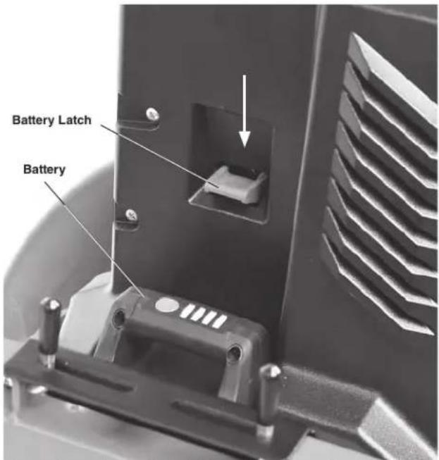
text_image
Battery Latch BatteryFigure 16 – Battery Latch (Handle Removed for Clarity)
Operating Instructions

text_image
WARNINGAlways wear eye protection to reduce the risk of eye injury.
Always wear RIDGID drain cleaning gloves in good condition. Latex or loose fitting gloves or rags can become wrapped around the cable and may result in serious personal injury. Only wear latex or rubber gloves under drain cleaning gloves. Do not use damaged drain cleaning gloves.
Always use appropriate personal protective equipment while handling and using drain cleaning equipment. Drains may contain chemicals, bacteria and other substances that may be toxic, infectious, cause burns or other issues. Appropriate personal protective equipment always include safety glasses and drain cleaning gloves, and may include equipment such as latex or rubber gloves, face shields, goggles, protective clothing, respirators and steel toed footwear.
Do not allow the cutter to stop turning while the machine is running. This can overstress the cable and may cause twisting, kinking or breaking of the cable. Twisting, kinking or breaking cable may cause striking or crushing injuries.
Keep glove covered hand on the cable whenever
the machine is running. This provides better control of the cable and helps prevent twisting, kinking and breaking of the cable. Twisting, kinking or breaking cable may cause striking or crushing injuries.
Position machine cable outlet within 3' (0.9 m) of the drain inlet or properly support exposed cable when the distance exceeds 3' (0.9 m). Greater distances can cause control problems leading to twisting, kinking or breaking of the cable. Twisting, kinking or breaking cable may cause striking or crushing injuries.
One person must control both the foot switch and cable. If the cutter stops rotating, the operator must be able to release the foot switch to prevent twisting, kinking and breaking of the cable. Twisting, kinking or breaking cable may cause striking or crushing injuries.
Follow operating instructions to reduce the risk of injury from twisted or broken cables, cable ends whipping around, machine tipping, chemical burns, infections and other causes.
-
Make sure that machine and work area is properly set-up and that the work area is free of bystanders and other distractions.
-
Pull cable out of drum and feed into drain. If needed, loosen AUTOFEED knob. Push cable as far into drain as it will go. At least one foot (.3 m) of cable must be in drain so that the end of the cable will not come out of the drain and whip around when the machine is started.
Directly route the cable from the outlet of machine to the drain opening, minimizing exposed cable and changes in direction. Do not tightly bend the cable – this can increase the risk of twisting or breaking. Assume a proper operating position to help maintain control of the cable and machine (see Figure 17):
- Be sure you can control the ON/OFF action of the foot switch and can quickly release the foot switch if needed. Do not press foot switch yet.
- You must be able to place at least one RIDGID drain cleaning glove covered hand on the cable to always control and support the cable.
- Be sure that you have good balance, do not have to overreach, and cannot fall on the foot switch, machine, the drain or other hazards.
- You must be able to reach the main ON/OFF switch and FOR/OFF/REV switch.
This operating position will help to maintain control of the cable and machine.
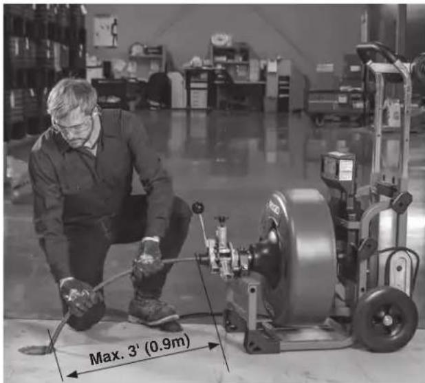
text_image
Max. 3' (0.9m)Figure 17 – Proper Operating Position
- Move the ON/OFF switch to the ON position. Move the FOR/OFF/REV switch to the FOR (FORWARD) position. Do not depress the foot switch yet. "FOR" and "REV" refers to the drum/cable rotation and not to the direction of cable movement. Do not rotate the cable in REV (reverse) except as specifically described in these instructions. Running the machine in REV can damage the cable.
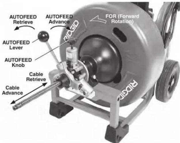
text_image
AUTOFEED Retrieve AUTOFEED Lever AUTOFEED Knob Cable Retrieve Cable Advance FOR (Forward Rotation) RIGIDFigure 18 – Cable Movement in FOR (Forward Rotation) NOTE: If Machine is set for REV (Reverse Rotation) AUTO-FEED advance and retrieve direction are opposite.
text_image
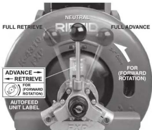
NEUTRAL FULL RETRIEVE RIFID FULL ADVANCE FOR (FORWARD ROTATION) FOR (FORWARD ROTATION) ADVANCE → RETRIEVE FOR (FORWARD ROTATION) AUTOFEED UNIT LABELFigure 19 – AUTOFEED Lever Positions (Cable Turning In FOR Direction)
NOTE: Rate of cable advance or retrieve varies by handle movement from neutral.
K-4310 FXP Drum Machine Operation
When using the K-4310 FXP Drum Machine, cable can be fed either manually or using the AUTOFEED unit. Generally, you can switch back and forth between operating methods as needed.
Advancing The Cable Into The Drain
Manual Operation
Confirm that at least one foot (0.3 m) of cable is in the drain. Grasp the exposed cable with both gloved hands equally spaced (Figure 20A) and pull 6"-12" of cable out of the drum (Figure 20B) so that there is a slight bow in the cable. Gloved hands must be on cable to control and support the cable. Improper cable support can allow the cable to kink or twist and can damage cable or injure the operator. Make sure that the cable outlet of drain cleaning machine is within 3' (0.9 m) of the drain opening.
Depress the foot switch to start the machine rotating in the FOR direction. The person controlling the cable must also control the foot switch. Do not operate the drain cleaning machine with one person controlling the cable and another person controlling the foot switch. This can lead to twisting, kinking and breaking of the cable. Advance the rotating cable into the drain. The rotating cable will work its way into the drain as you push on the cable with gloved hands (Figure 20C). Do not allow the cable to build up outside the drain, bow or curve. This can allow the cable to twist, kink or break.
When the cable has been fed into the drain opening, pull 6"-12" more cable from the drum and continue feeding the rotating cable into the drain.
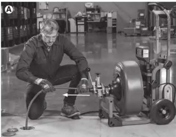
natural_image
Factory worker operating machinery with a tool, no visible text or symbols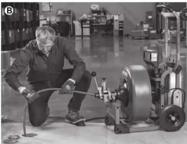
natural_image
Factory worker operating machinery with hoses and a large motor (no visible text or symbols)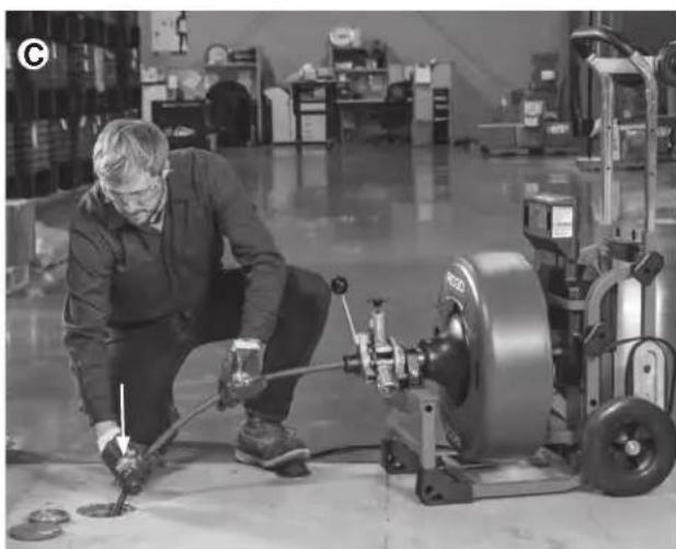
natural_image
Factory worker operating a tireblading machine with tools, surrounded by machinery and workbenches (no visible text or symbols)Figure 20A,B,C – Manual Feed Operation
AUTOFEED Cable Feed Operation
Confirm that the AUTOFEED unit is set up for the correct cable size, see "Adjusting AUTOFEED Unit For Cable Diameter" section.
With at least one foot (.3 m) of cable is in the drain. Tighten the AUTOFEED knob (Figure 18) so that the roller touches the cable plus one additional turn. Do not over-tighten the knob – this can cause premature failure of the AUTOFEED unit or cable.
Grasp near the center of the exposed length of cable with a gloved hand (Figure 21). Gloved hand must be on the cable to control and support the cable. Improper cable support can allow the cable to kink or twist and can damage the cable or injure the operator. Make sure that the cable outlet of the drain cleaning machine is within 3' (0.9 m) of the drain opening. Place the other hand on the AUTOFEED lever. The lever should be in neutral (Vertical) position (see Figure 19).
See "Using Machine With A Front Guide Hose" if using a guide hose.
Depress the foot switch to start the machine rotating in the FOR direction. The person controlling the cable must also control the foot switch. Do not operate the machine with one person controlling the cable and another person controlling the foot switch. This can lead to twisting, kinking and breaking of the cable. With the cable rotating, move the AUTOFEED control lever in the opposite direction that the cable rotates (See Figure 19). This will cause the cable to advance out of the machine. The further the control lever from the neutral position, the faster the cable will advance.
The rotating cable will work into the drain as you control the cable with your gloved hand. Do not allow the cable to build up outside the drain, bow or curve. This can allow the cable to twist, kink or break.
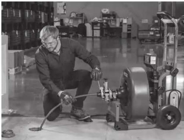
natural_image
Man operating industrial machinery in a warehouse setting (no visible text or symbols)Figure 21 – Operating using the AUTOFEED Unit
Passing Through Traps Or Other Transitions
If it is difficult to get the cable through a trap or other fitting, the following methods or combinations of methods can be used.
- Sharp thrusts of the cable, both with and without the cable rotating, can help the cable through a trap.
- In some cases, with the switch in the OFF position, rotating the drum by hand can change the orientation of the cutter to allow it to negotiate the fitting more easily.
- Run the machine in REV (REVERSE) rotation for several seconds while pushing on the cable. Only do this long enough to get the cable started through the trap. Running the cable in reverse can damage the cable.
• Use a flexible leader between the tool and the cable.
If these options don't work, consider using a smaller diameter or more flexible cable, or a different RIDGID drain cleaning machine.
Cleaning The Drain
As you advance the cable into the drain, you may see the cable slow down or build up outside the drain. Always keep your hands on the cable. You may feel the cable start to wind or load up (this may feel like the cable is starting to twist or squirm, see Figure 22.) This may be a transition in the drain (trap, elbow, etc.), build up in the drain (grease, etc.) or the actual blockage. Advance the cable slowly and carefully. Do not let cable build up outside the drain. This can cause the cable to twist, kink or break.
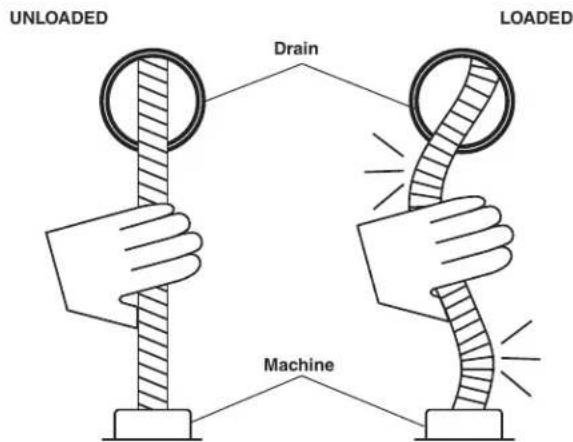
text_image
UNLOADED Drain LOADED MachineFigure 22 - Cable Shape When Unloaded, Loaded
Pay attention to the amount of cable that has been fed into the drain. Feeding cable into a larger drain, septic tank or similar transition may cause the cable to kink or knot and prevent removal from the drain. Minimize the
amount of cable fed into the transition to prevent problems.
If an additional length of cable is needed, see the section "Adding Additional Cable".
Working The Blockage
If the end of the cable stops turning, it is no longer cleaning the drain. If the end of the cable becomes lodged in the blockage and power is maintained to the machine, the cable will start to wind up (this may feel like the cable is starting to twist or squirm). Having a hand on the cable allows you to feel this wind up and control the cable. If the cable end stops turning or if the cable starts to wind up, immediately pull the cable back from the obstruction:
- Manual Operation – pull back on the cable to free the cable end from the blockage.
- AUTOFEED Unit Operation – move the AUTOFEED lever to retrieve direction to free the cable end of the blockage.
Do not keep the cable rotating if the cable is stuck in a blockage. If the cable end stops turning and the drum keeps rotating, the cable can twist, kink or break.
Once the cable end is free of the blockage and turning again, you can slowly feed the cable end back into the blockage. Do not try to force the cable end through the blockage. Let the spinning end "dwell" in the blockage to completely break it up. Work the tool in this manner until you have moved completely past the blockage (or blockages) and the drain is flowing. Manual operation is usually the best choice if the cable repeatedly gets stuck when using the AUTOFEED unit. If using an AUTOFEED unit machine manually, the AUTOFEED knob may need to be loosened, and the AUTOFEED lever placed in the neutral position.
While working the blockage, the cable and tool may become clogged with debris and cuttings from the blockage. This can prevent further progress. The cable and tool need to be retrieved from the drain and the debris removed. See section on “Retrieving the Cable”.
Handling A Stuck Tool
If the tool stops turning and the cable cannot be pulled back from the blockage, immediately release the foot switch while firmly holding the cable. Do not remove hands from cable or cable may kink, twist and break. The motor will stop and the cable and drum may turn backwards until the energy stored in the cable is relieved. Do not remove hands from cable until the tension is released. Place FOR/OFF/REV switch in OFF position. Do not move the main ON/OFF switch to OFF position if recording, this will cause a data interruption and may not allow chart generation.
Freeing A Stuck Tool
If the tool is stuck in the blockage, with the FOR/OFF/REV switch in the OFF position and the foot switch released, try pulling the cable loose from the blockage. If the tool will not come free from the blockage, place the FOR/OFF/REV switch in REV position. Grasp the cable with both gloved hands, press the foot switch for several seconds and pull on the cable until it is free of the blockage. Do not operate the machine in the REV position any longer than required to free (unscrew) the cutting tool from the blockage or cable damage can occur. Place the FOR/OFF/REV switch in the FOR position and continue cleaning the drain.
Retrieving The Cable
Once the drain is open, start a flow of water down the drain to flush the debris out of the line. This can be done by running a hose down the drain opening, turning on a faucet in the system or other methods. Pay attention to the water level, as the drain could plug again.
With water flowing through the drain, retrieve the cable from the line. The flow of water will help to clean the cable as it is retrieved. The FOR/OFF/REV switch should be in the FOR position – do not retrieve the cable with the switch in the REV position, this can damage the cable. As with feeding the cable into the drain, cables can be caught while being retrieved.
- Manual Operation – With both gloved hands equally spaced on the exposed cable for control, pull 6"-12" lengths of cable from the drain at a time and feed it into the drum.
- AUTOFEED Unit Operation – With one hand near the center of the exposed length of cable, move the AUTOFEED lever to the retrieve position. The rotating cable will work its way out of the drain and back into the drum.
Continue retrieving cable until the cable end is just inside the drain opening. Release the foot switch and allow the machine to come to a complete stop. Do not pull the end of the cable from the drain while the cable is rotating. The cable can whip around and cause serious injury. Pay attention to the cable during retrieval as the cable end can still become stuck.
Place the FOR/OFF/REV switch in the OFF position. Pull the remaining cable from the drain with gloved hands and feed back into the machine. Place the main ON/OFF switch in the OFF position.
If needed, change the tool and continue cleaning following the above process. Several passes through a line are recommended for complete cleaning.
RIDGID Link App Connection (Wireless Communication)
The RIDGID® K-4310 FXP Drum Machine includes wireless technology allowing communication to properly equipped smartphones or tablets ("devices") running iOS or Android operating systems. This allows the user to create shareable job insights and access tool history data.
- Download the appropriate RIDGID® Link app to your device by going to RIDGID.com/apps, the Google Play Store or the Apple App Store.
- When the machine is powered and the ON/OFF switch is ON, the (p) light will blink blue when connection to a device is possible. See Figure 5.
- Find the RIDGID Link app icon on your device and launch the app by selecting the icon. Via the app, search for nearby tools and select the desired RIDGID tool. Refer to your device instructions for specific information on how to connect via wireless technology. Once connected, the (↑) light will be lit blue.
After the initial pairing, most devices will automatically connect to the machine when the wireless technology is active and in range and if device settings are configured to do so. Machine should be less than 33 ft. (10 m) from the device to be detected. Any obstacle between the machine and device can reduce the operational range.
- Follow the app instructions for use. Do not let the use of the app distract you from monitoring the drain cleaning process. Inattention to the process can cause you to lose control.
- The wireless communication turns off when the main ON/OFF switch is turned to OFF or power removed. Turn wireless communication OFF on the device to reduce device battery drain.
Other Operating Instructions
Using Machine With A Front Guide Hose
The front guide hose is an optional accessory to help protect fixtures and contain the liquid and debris on the cable. It can only be used with an AUTOFEED unit. Using the front guide hose can decrease feedback from the cable, making it harder to tell what conditions the cable is encountering. This may increase the possibility of damage to the cable. Using the front guide hose makes it more difficult to switch back and forth between manual and AUTOFEED unit operation.
Using a machine with the front guide hose is similar to using a machine with just the AUTOFEED unit. Follow instructions for AUTOFEED unit operation with the following exceptions:
- When setting up the machine, insert the guide hose at least 6" into the drain.
- Instead of holding the cable, hold the guide hose. See Figure 23. Always control the guide hose and properly support the cable to prevent the cable from twisting, kinking or breaking.

natural_image
Man operating industrial machinery in a factory setting (no visible text or symbols)Figure 23 – Using Machine with Guide Hose
When using a front guide hose, pay attention how the guide hose feels in your hand and watch the drum rotation. Because the guide hose is over the cable, there is less sensitivity to the loading of the cable, and it is harder to tell if the tool is rotating or not. If the tool is not rotating, the drain is not being cleaned.
If the tool continues to get hung up in the blockage, stop using the AUTOFEED unit (leave the AUTOFEED lever in the neutral position) and work the cable manually. To do this, the cable must be retrieved from the drain and the guide hose removed to allow proper positioning of the machine to the drain and access to the cable. Do not try to work the cable by hand with the front guide hose in place.
When retrieving the cable, be sure to stop the cable before the tool hits the end of the guide hose to prevent damage.
Adding Additional Cable
If more cable is necessary than in the machine drum, use the following procedure to add additional cable. Do not exceed the drain cleaner ratings.
Note the cable travel values before adding additional cable. Cable parameters will be lost during adding additional cable. The cable parameters need to be filled again and the cable travel reset after adding additional cable. The final cable travel will be previous cable travel plus the additional cable travel.
- Note the cable travel values.
- Make sure that the main ON/OFF switch is in the OFF position and the battery/power adapter removed.
- Pull the cable connection from the drum. If using AUTOFEED unit, the AUTOFEED knob may need to be loosened.
- Disconnect the cable from pigtail and secure the cable so it cannot slip down the drain.
- If loading another cable in the existing drum, see "Installing Cable" section. If using a second drum of cable, see "Changing Drums".
- Attach the end of the cable in the drain to the cable in the drum. Feed any excess cable back into the drum.
- With the machine powered on, properly setup the cable values and reset the cable travel value to zero. See "Setting Cable Information" section. The cable travel value will be previous cable travel plus the additional cable travel shown on the control panel.
- Resume cleaning the drain. Make sure that the cable is rotating and up to speed before feeding cable in.
Changing Drums
Note the cable travel values before changing drum. Cable parameters will be lost while changing drum. The cable parameters need to be filled again and the cable travel reset after changing drum. The final cable travel will be previous cable travel plus the additional cable travel.
- Note the cable travel values.
- Make sure that the main ON/OFF switch is in the OFF position and the battery/power adapter removed.
- Remove the AUTOFEED unit from the machine, leaving the drum retainer open.
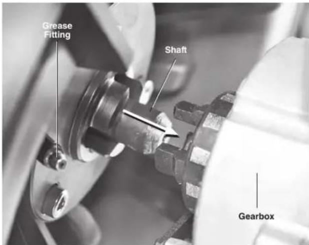
- Securely grasp the drum and slide it approximately 1" (25 mm) away from the gearbox (Figure 24).
- Carefully lift the drum out of the machine. Be aware that depending on the cable in the drum, it could weigh up to 155 lbs. (70 kg).
- Reverse process to install drum. Align shaft on back of drum with gearbox and slide the drum toward the gearbox (Figure 24). With hands clear of pinch points, tip the machine back on the wheels and rotate drum
slowly to allow drum to fully seat. Securely close drum retainer. If cable size is being changed, AUTOFEED unit may need to be adjusted.
text_image
Grease Fitting Shaft GearboxFigure 24 – Changing Drum (Drum Retainer Open, Sliding Back)
- With the machine powered on, properly setup the cable values and reset the cable travel value to zero. See "Setting Cable Information" section. The cable travel value will be previous cable travel plus the additional cable travel shown on the control panel.
Draining The Machine
If the machine needs to be drained, turn machine OFF and remove power from machine. Remove the battery/power adapter. Remove the screw plug located in the rear of the drum (Figure 25) and rotate/tip the drum to allow it to drain. Be sure to replace the drain plug.
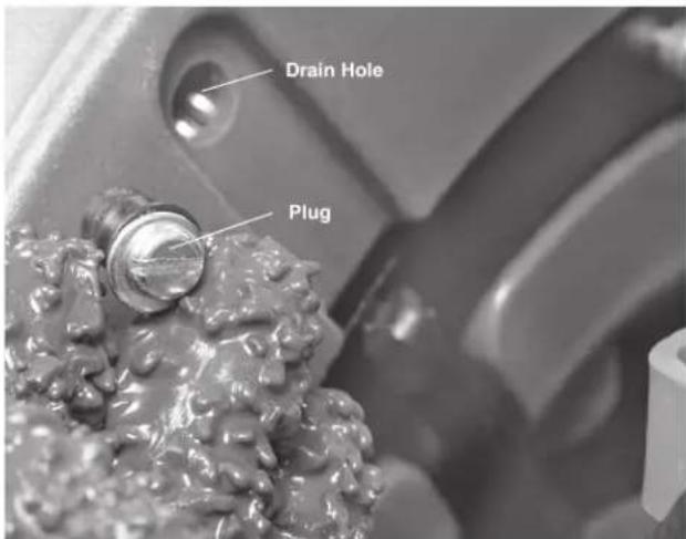
text_image
Drain Hole PlugFigure 25 – Drum Drain Hole
Transportation And Storage
Transportation
Feed all of the cable into the drum. Remove any cutter or tool from the cable. Make sure that no more than 6" cable is outside the drum. Tighten the AUTOFEED knob onto the cable. Wrap the foot switch hose around foot switch hose wrap. See Figure 27.
Before moving the machine, make sure that the telescoping handle is secured into the extended position for transport. If the machine needs to be lifted, use proper lifting techniques. Use care moving equipment on stairs and be aware of possible slip hazards.
Manual Loading
With the telescoping handle locked into the extended position, place machine with wheels toward the vehicle. Lean the machine back and rest the loading wheels on the vehicle bed. Use loading handles to lift the machine and slide it onto the vehicle (Figure 26). Use care not to damage foot switch hose. Be aware of the machine weight. Use proper lifting techniques – more than one person may be required.
Loading with Crane/Winch
If lifting with a crane/winch, entire machine weight can be carried with handle. Lock the telescoping handle into lowest position for lifting. Depending on which drum is being used the angle in which the machine rests may vary (Figure 27).

natural_image
Man standing beside a vehicle with an electric scooter being loaded, no visible text or symbolsFigure 26 – Loading on a Vehicle

natural_image
Mechanical tire assembly with attached motor and wheels (no visible text or symbols)Figure 27 - Loading with Crane/Winch
Storage
WARNING FXP Drum Machine must be kept dry and indoors or well covered if kept outdoors. Store the machine in a locked area that is out of reach of children and people unfamiliar with drain cleaning machines. This machine can cause serious injury in the hands of untrained users.
Maintenance Instructions
WARNING
The main ON/OFF switch should be OFF and battery or adapter removed before performing any maintenance. Always wear safety glasses and other appropriate protective equipment when performing any maintenance.
Cleaning
After each use, clean the machine. A mild detergent or antibacterial solution can be used if desired. Do not use solvents, abrasives or other harsh cleaning agents.
Machine – Use a damp, soft cloth to wipe off the machine. Do not submerge or flush the machine with water. Do not allow water to enter motor or other electrical components. Make sure unit is completely dry before inserting battery or adapter and using.
Drum and Cable – Flush the drum and cable with water after every use to prevent damaging effects of sediment and drain cleaning compounds. Allow to dry to reduce cable corrosion.
AUTOFEED Unit – Flush AUTOFEED unit assembly with water.
Guide Hose (Optional accessory) – Flush with water and drain.
Cleaning the Cable Travel Sensors
- Remove the AUTOFEED unit.
- Check front sensor pickup for wear and debris, wipe clean with a soft cloth.
- Using a 3mm Hex Wrench, remove the front sensor cover.
- Check front Hall sensor for wear and damage, wipe clean as necessary.
- Following the Changing Drums section, remove the machine drum and repeat the cleaning process for rear cable travel sensor.
- Reinstall the sensor covers and drum.
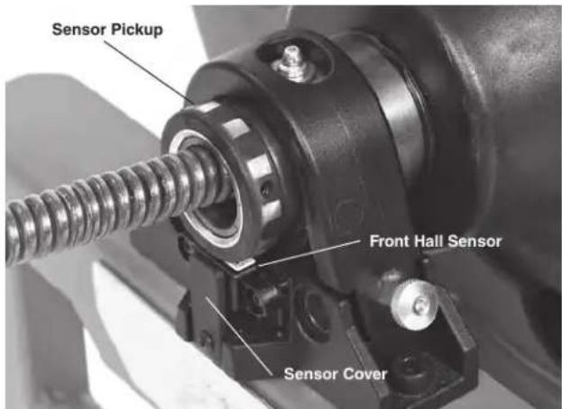
text_image
Sensor Pickup Front Hall Sensor Sensor CoverFront Cable Travel Sensor
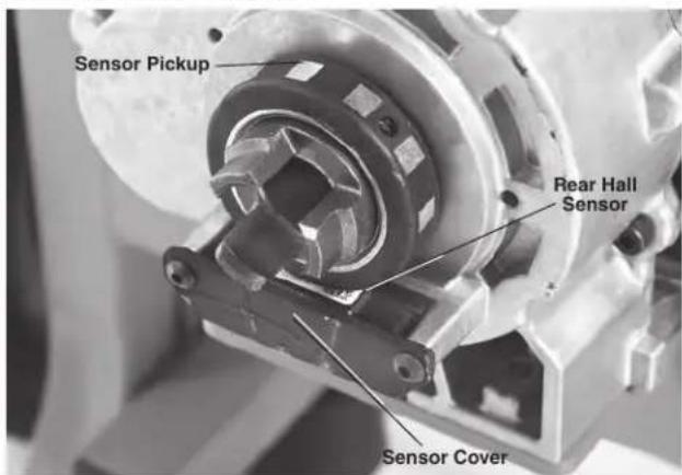
text_image
Sensor Pickup Rear Hall Sensor Sensor CoverRear Cable Travel Sensor
Figure 28 – Cleaning the Cable Travel Sensors
Lubrication
Lubricate machine with general purpose grease at grease fitting located at connection of guide tube and drum (Figure 7), back side of the drum (Figure 24) and on AUTOFEED Unit (Figure 9). Lubricate anytime the drum is changed or removed, anytime grease may have been removed by cleaning, and at minimum, every 20 Hours of runtime.
Changing Cable
- Pull all the cable out from the drum.
- Disconnect the cable end from pigtail. See Figure 15.
- Install the new cable per Installing Cable section.
In certain abnormal circumstances (such as worn or damaged cable, keeping the drum rotating while the cable end is stuck in an obstruction. etc.) the cable may flip over in the machine drum. This is typically accompanied by a loud noise and may prevent the cable from moving in and out of the drum. Looking into the drum, the cable will be tangled and disorganized, instead of neatly coiled. The cable may be permanently damaged.
Use caution when removing the flipped cable from the drum. The cable may be under load and could move unexpectedly, springing out of the drum or wrapping and flipping further, which increases the risk of injury. It may be necessary to disassemble the drain cleaner to remove the cable (see pigtail replacement section for details) In some cases the cable may need to be cut with bolt cutters to remove it from the drum.
Pigtail Replacement
- Remove all cable from the drum except the pigtail.
- Remove the AUTOFEED unit assembly from the machine. Remove the drum.
- Remove sensor pickup set screw, then bearing retaining clip.
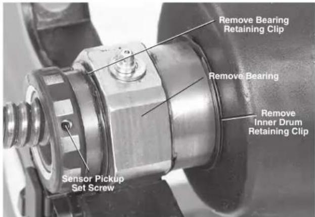
text_image
Remove Bearing Retaining Clip Remove Bearing Remove Inner Drum Retaining Clip Sensor Pickup Set ScrewFigure 29 – Remove Retaining Ring and Inner Drum
- Remove the outer retaining clip from the guide tube shaft (Figure 29). Slide bearing off the shaft.
- Remove retaining ring holding inner drum in place and remove inner drum.
- Remove the bolt anchoring the pigtail. It is located on the back of the drum (Figure 30).
- Remove the pigtail from the guide tube and drum. Insert new pigtail into the drum following the guide tube curve and FOR drum arrow.
- Align hole in pigtail with the hole in the back of the drum. Insert bolt, washers and nut and tighten securely. Push the remainder of the pigtail into drum.
- Push the end of the pigtail through guide tube. Install
inner drum, bearing and sensor ring by reversing steps 3, 4 and 5. Make sure everything is properly installed per Figure 29 and secure.
- Install the drum assembly onto the machine.
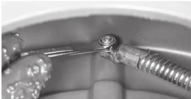
natural_image
Close-up of a metal screw being inserted into a container (no visible text or symbols)Figure 30 – Pigtail Anchor Bolt
Troubleshooting
| SYMPTOM POSSIBLE REASONS SOLUTION | ||
| Cable kinking or breaking. | Cable is being forced. | Do Not Force Cable! Let the cutter do the work. |
| Cable used in incorrect pipe diameter. | Use correct cable for pipe size. | |
| Motor switched to reverse. | Use reverse only if cable gets caught in pipe. | |
| Cable exposed to acid. | Clean cables routinely. | |
| Cable worn out. | If cable is worn, replace it. | |
| Cable not properly supported. | Support cable properly, see instructions. | |
| Drum stops while pedal is depressed. | Hole in pedal or connecting hose. | Have machine serviced. |
| Restarts when pedal is re-depressed. | Hole in diaphragm switch. | Have machine serviced. |
| Cable turns in one direction but not the other. | Faulty FOR/OFF/REV switch. | Have machine serviced. |
| Machine will not run. | Machine is in hibernation mode. | Turn machine ON/OFF. |
| Battery is completely discharged or battery has failed. | Insert fully charged battery/replace battery. | |
| Battery not properly inserted into port of tool. | Check to assure battery is fully inserted. | |
| FXP Power Adapter not correctly inserted into the tool. | Correctly insert Power Adapter into tool. | |
| AUTOFEED unit does not work properly. | AUTOFEED unit is not routinely cleaned and filled with debris. | Clean AUTOFEED unit. |
| AUTOFEED unit is not greased enough. | See Lubrication section. | |
| Machine wobbles or moves while cleaning drain. | Cable not evenly distributed. | Pull all cable out and feed in again, evenly distribute. |
| Bumpers are not on ground. | Place on level stable surface. | |
| Ground not level. | Place on level stable surface. | |
| Advanced Display and Control Panel Malfunction. | Advanced Display and Control Panel Malfunction. | Have machine serviced. |
| Cable travel values changes exponentially. | Sensors not properly seated. | Confirm that drum and gearbox sensor pickups are properly positioned and secure. Tighten sensor pickup set screw if needed. |
| Dirt on sensors. | Clean the sensors. | |
| Wiring damaged. | Have machine serviced. | |
| AUTOFEED unit Latch Assembly Worn. | Replace Worn Components. | |
Service And Repair
WARNING
Improper service or repair can make the machine unsafe to operate.
The "Maintenance Instructions" will take care of most of the service needs of this machine. Any problems not addressed by this section should only be handled by a RIDGID Authorized Independent Service Center. Use only RIDGID service parts.
For information on your nearest RIDGID Authorized Independent Service Center or any service or repair questions see Contact Information section in this manual.
Optional Equipment
WARNING
To reduce the risk of serious injury, only use accessories specifically designed and recommended for use with the RIDGID K-4310 FXP Drum Machine, such as those listed below.
| Catalog No. | Model No. | Description |
| 73098 — | Drum, K-4310 FXP, 58" | |
| 73093 — | Drum, K-4310 FXP, 34" | |
| 73083 — | AUTOFEED Cable Feed Unit | |
| 49032 — | Front Guide Hose Assembly | |
| 70032 — | PVC Drain Cleaning Gloves |
Cables
| Catalog No. | Model No. | Description |
| 92460 C-25 | 78 " (16mm) x 25' IC Cable (7.6m) | |
| 92465 C-26 | 78 " (16mm) x 50' IC Cable (15.2m) | |
| 92470 C-27 | 78 " (16mm) x 75' IC Cable (22.9m) | |
| 43647 C-24 | 78 " (16mm) x 100' IC Cable (30.5m) | |
| 92475 C-28 | 78 " (20mm) x 25' IC Cable (7.6m) | |
| 92480 C-29 | 78 " (20mm) x 50' IC Cable (15.2m) | |
| 41212 C-75 | 78 " (20mm) x 75' IC Cable (22.9m) | |
| 41697 C-100 | 78 " (20mm) x 100' IC Cable (30.5m) |
| Catalog No. | Model No. | Description |
| 32737 C-27HC | ^5/e'' (16mm) x 75' HC Cable (23m) | |
| 58192 C-24HC | ^5/e'' (16mm) x 100' HC Cable (30.5m) | |
| 47427 C-75HC | ^3/4'' (20mm) x 75' HC Cable (23m) | |
| 47432 | C-100HC | ^3/4'' (20mm) x 100' HC Cable (30.5m) |
Leaders and Pigtails
| Catalog No. | Model No. | Description |
| 44117 — | ^3/_4 " Pigtail Assembly | |
| 44122 — | ^5/_8 " Pigtail Assembly | |
| 92555 T-4 | 58 | ^5/_8 " (16mm) x 2' (610mm) Leader |
| 92560 T-4 | 68 | ^3/_4 " (20mm) x 2' (610mm) Leader |
Tools
| Catalog No. | Model No. | Description |
| 51762R T- | 409 H-D Bulb | Auger, 1 34 " (45mm) |
| 92485 T-4 | 03 P-Trap Cutter, 3" (75mm) | |
| 92490 T-4 | 04 P-Trap Cutter, 3 | 12 " (89mm) |
| 92495 T-4 | 06 Spade Cutter, 1 | 74 " (45mm) |
| 92500 T-4 | 07 Retrieving | Auger 2 116 " (65mm) |
| 92505 T-4 | 08 Sawtooth | Cutter, 3" (75mm) |
| 92510 T-4 | 11 Double Cutter, 2" (50mm) | |
| 92515 T-4 | 12 Double Cutter, 2 | 12 " (65mm) |
| 92520 T-4 | 13 Double Cutter, 3" (75mm) | |
| 92525 T-4 | 14 Double Cutter, 4" (100mm) | |
| 92530 T-4 | 16 Double Cutter, 6" (150mm) | |
| 92535 T-4 | 32 3-Blade Cutter 2" (50mm) | |
| 92540 T-4 | 33 3-Blade Cutter 3" (75mm) | |
| 92545 T-4 | 34 3-Blade Cutter 4" (100mm) | |
| 92550 T-4 | 36 3-Blade Cutter 6" (150mm) | |
| 68623 — | Bag, Drain Cleaning Bag Only | |
| 59230 A-1 | 3 | 18 " Cable Pin Key |
Battery and FXP Power Adapter Packs
| Catalog No. | Description |
| 70788 RB | -FXP40 4.0AH Battery |
| 70793 RB | -FXP80 8.0AH Battery |
Chargers and Cords
| Catalog No. | Description |
| 70798 REC-FXP-NA Charger | |
For a complete listing of RIDGID equipment available for this machine, see the Ridge Tool Catalog online at RIDGID.com or see Contact Information.
Disposal
Parts of these tools contain valuable materials and can be recycled. There are companies that specialize in recycling that may be found locally. Dispose of the components in compliance with all applicable regulations. Contact your local waste management authority for more information.

For EC Countries: Do not dispose of electrical equipment with household waste!
According to the European Guideline 2012/19/EU for Waste Electrical and Electronic Equipment and its implementation into national legislation, electrical equipment that is no longer
usable must be collected separately and disposed of in an environmentally correct manner.
natural_image
Two identical RIDGID electric lift machines shown side by side, no visible text or symbols on the device body.AVERTISSEMENT!
NOTICE indicates information that relates to the protection of property.

The term "power tool" in the warnings refers to your mains-operated (corded) power tool or battery-operated (cordless) power tool.
Sécurité des lieux
text_image
RIDGE Tool Company, Elyria, Ohio, U.S.A. RIDGID.com Model No. Serial No. XXXXXMMYY V### No /min Interbelcnatural_image
Three types of industrial gloves: one with visible texture and labels, another with textured surface (no readable text or symbols)text_image
3' (90 cm) maxinatural_image
Illustration of two types of threaded fasteners, labeled 1 and 2, showing different end caps and mounting points (no text or symbols present)text_image
Technical diagram showing two steps of a coiled spring with labeled parts ① and ②text_image
Loquet de bloc-piles Bloc-pilestext_image
3' (90 cm) maxinatural_image
Mechanic working with a machine in a factory setting (no visible text or symbols)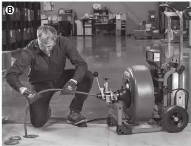
natural_image
Factory worker operating machinery with a large wheel and pipe (no visible text or symbols)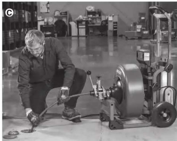
natural_image
Factory worker operating machinery in a warehouse (no visible text or symbols)natural_image
Factory worker operating machinery in a warehouse (no visible text or symbols)natural_image
Factory worker operating a pump and machine in a warehouse setting (no visible text or symbols)natural_image
Man standing beside a vehicle with a cart being loaded, no visible text or symbolsnatural_image
Mechanical testing machine with dual wheels and a central circular component (no visible text or symbols)natural_image
Close-up of a mechanical tool interacting with a metallic screw and nut (no visible text or symbols)Battery and FXP Power Adapter Packs
| Réf. catalogue | Description |
| 70788 | Bloc-piles RB-FXP40 4,0 Ah |
| 70793 | Bloc-piles RB-FXP80 8,0 Ah |
natural_image
Two identical RIDGID industrial machines with wheels and control panels, shown from different angles (no visible text or symbols on the machines themselves)
ADVERTENCIA
text_image
RIDGE Tool Company, Elyria, Ohio, U.S.A. RIDGID.com Model No. Serial No. XXXXXMMYY V... n₀ /min interbekalmacenamiento.....-4° F to 140° F (-20° C to 60° C)
natural_image
Pair of white industrial gloves with visible wear and branding (no readable text or symbols)
natural_image
Two textured gloves with visible surface texture and labels, no readable text or symbols on the gloves themselves.natural_image
Illustration of two types of threaded fasteners, labeled ① and ②, showing different end caps and mounting points (no text or symbols present)text_image
Diagram showing two steps of a coiled spring with labeled parts and directional arrowsnatural_image
Mechanic operating a machine in a workshop (no visible text or symbols)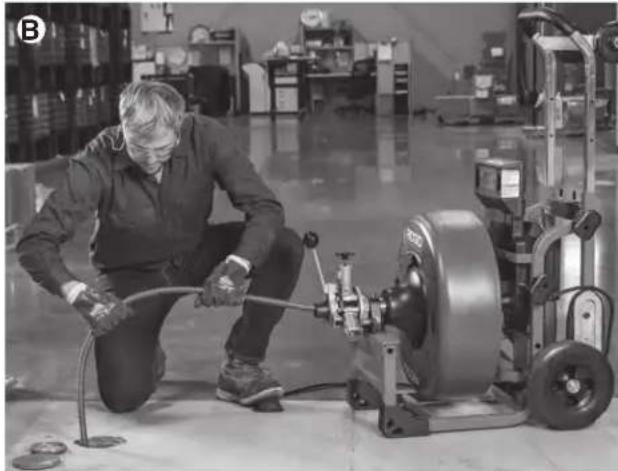
natural_image
Factory worker operating machinery with hoses and a large motor (no visible text or symbols)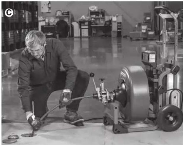
natural_image
Factory worker inspecting machinery with tools in a warehouse (no visible text or symbols)natural_image
Factory worker operating machinery in a warehouse (no visible text or symbols)natural_image
Man operating a mechanical pump in a warehouse setting (no visible text or symbols)natural_image
Man standing beside a vehicle with an electric scooter being loaded, no visible text or symbolsnatural_image
Mechanical tire and wheel assembly (no visible text or symbols)natural_image
Close-up of a metal screw being inserted into a container (no text or symbols visible)Figura 30 – Perno de anclaje del acoplamiento flexible pigtail
This device complies with Part 15 of the FCC Rules. Operation is subject to the following two conditions:
- This device may not cause harmful interference.
- This device must accept any interference received, including interference that may cause undesired operation.
Modifications not expressly approved by this company could void the user's authority to operate the equipment.
NOTE: This equipment has been tested and found to comply with the limits for a Class A digital device, pursuant to part 15 of the FCC Rules. These limits are designed to provide reasonable protection against harmful interference when the equipment is operated in a commercial environment. This equipment generates, uses, and can radiate radio frequency energy and, if not installed and used in accordance with the instruction manual, may cause harmful interference to radio communications. Operation of this equipment in a residential area is likely to cause harmful interference in which case the user will be required to correct the interference at his own expense.
This product complies with the Canadian ICES-003 Class A specifications. See Declaration label on tool.
RIDGID® K-4310 FXP Drum Machine
MANUFACTURER
RIDGE TOOL COMPANY
400 Clark Street
Elyria, Ohio 44035-6001
U.S.A.
ProToolsRegulatory.Compliance@Emerson.com

5011050
UL62841-1, UL62841-3-14, CSA C22.2#62841-1, CSA22.2#62841-3-14

Signature
Qualification: V.P. Engineering
Date: 04/09/2025
What is covered
RIDGID® tools are warranted to be free of defects in workmanship and material.
How long coverage lasts
This warranty lasts for the lifetime of the RIDGID ^® tool. Warranty coverage ends when the product becomes unusable for reasons other than defects in workmanship or material.
How you can get service
To obtain the benefit of this warranty, deliver via prepaid transportation the complete product to RIDGID ^® c/o Emerson Professional Tools, LLC in, Elyria, Ohio, or any RIDGID ^® AUTHORIZED INDEPENDENT SERVICE CENTER. Pipe wrenches and other hand tools should be returned to the place of purchase.
What we will do to correct problems
Warranted products will be repaired or replaced, at RIDGID's option, and returned at no charge; or, if after three attempts to repair or replace during the warranty period the product is still defective, you can elect to receive a full refund of your purchase price.
What is not covered
Failures due to misuse, abuse or normal wear and tear are not covered by this warranty. Seller is not responsible for any incidental or consequential damages.
How local law relates to the warranty
Some states do not allow the exclusion or limitation of incidental or consequential damages, so the above limitation or exclusion may not apply to you. This warranty gives you specific rights, and you may also have other rights, which vary, from state to state, province to province, or country to country.
No other express warranty applies
This FULL LIFETIME WARRANTY is the sole and exclusive warranty for RIDGID ^® products. No employee, agent, dealer, or other person is authorized to alter this warranty or make any other warranty on behalf of RIDGID ^® .
To obtain further warranty information on your product please visit www.RIDGID.com/us/en/warranty

text_image
RIDGID FULL LIFETIME WARRANTY Against Material Defects & WorkmanshipParts are available online at Store.RIDGID.com
RIDGID
Emerson Professional Tools, LLC
400 Clark Street
Elyria, Ohio 44035-6001
U.S.A.