
TG500AL - Smoke detector HAGER - Free user manual and instructions
Find the device manual for free TG500AL HAGER in PDF.
| Product Type | Optical smoke detector |
| Brand | Hager |
| Model | TG500AL |
| Use | Indoor, private parts of dwellings, mobile homes, camper vans |
| Dimensions (Diameter x Height) | 125 mm x 48 mm |
| Weight | 210 g |
| Power supply | 9 V alkaline battery (type 6LR61) or 9 V Lithium battery (type U9VL-J-P) |
| Battery life | Approximately 4 years (alkaline) or 10 years (Lithium) |
| Coverage | 50 m² (average) |
| Operating temperature | -10 °C to +55 °C |
| Protection rating | IP32 |
| Alarm sound level | 85 dB(A) at 3 m (continuous on triggering detector, modulated on others) |
| Wired interconnection | Up to 40 detectors, max. cable 400 m (section 1.5 mm²) |
| Main functions | Optical smoke detection, audible and visual alarm, manual test, 15 min inhibition, fault signaling (low battery or dirty head), white emergency light |
| Maintenance and cleaning | Dust the slots of the head with a vacuum cleaner at least once a year or when the dirty head signal appears; do not paint the detector |
| Safety | Monthly test recommended; never test with a naked flame; plan an evacuation route |
| Spare parts and repairability | Replaceable battery (type 9 V); detection head not separately replaceable; total detector lifespan: 10 years |
| General information | Standard DIN EN 14604:2005; 24-month warranty; optional anti-theft locking |
Frequently Asked Questions - TG500AL HAGER
User questions about TG500AL HAGER
0 question about this device. Answer the ones you know or ask your own.
Ask a new question about this device
Download the instructions for your Smoke detector in PDF format for free! Find your manual TG500AL - HAGER and take your electronic device back in hand. On this page are published all the documents necessary for the use of your device. TG500AL by HAGER.
USER MANUAL TG500AL HAGER
Entretoises de fixation (11 mm)
B


TG 501A
TG 501A / TG 501(AL)TG 500A / TG 500(AL)
- Operation principle...... 26
- Description.... 27
Power supply...... 28
Installation of the detector ..... 28
- Selection of the installation location 28
- Fixing.... 29
- Installing several detectors in a network .... 30
Testing the detector.... 31
Manual disabling of the detector.... 32
Indication of faults 32
- Power supply fault...... 32
- Indication of detection head clogging 33
Maintenance.... 33
- Detection head maintenance..... 33
- Battery replacement.... 34
- In case of works 34
User sheet 35 - 36
Technical characteristics...... 37
TG 500A (white)
TG 500B (silver)
TG 501A (white)
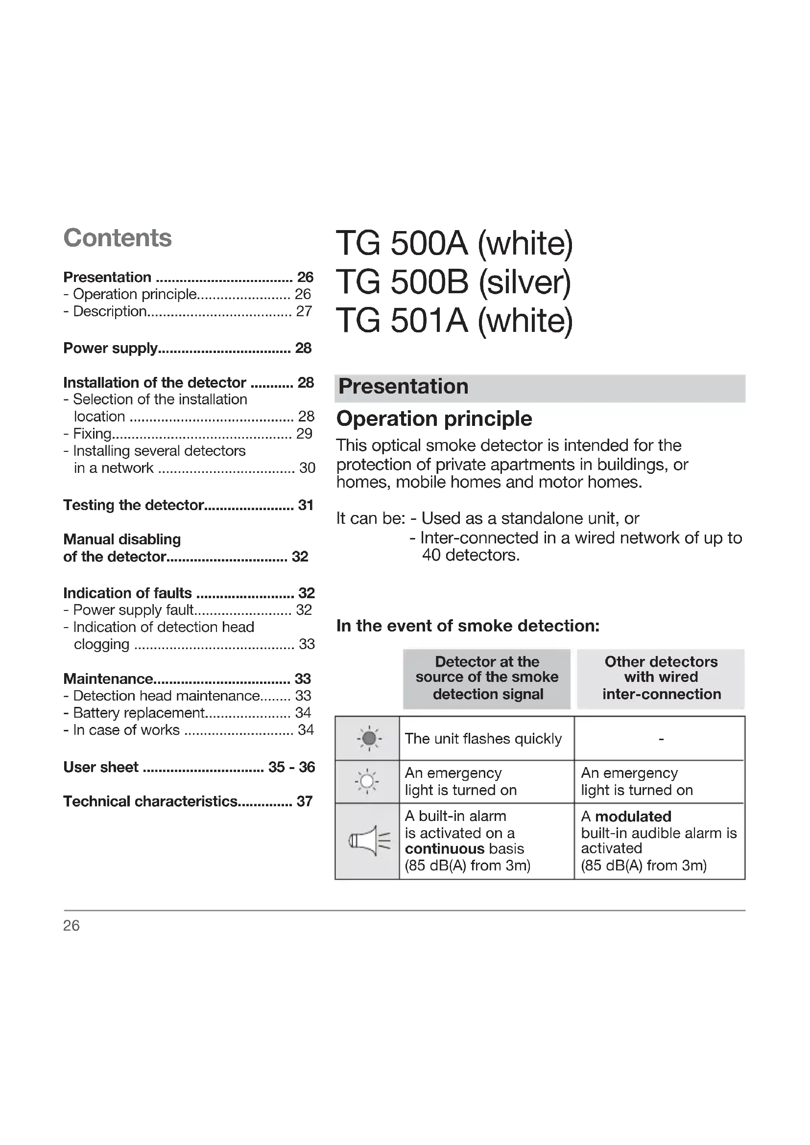
Presentation
Operation principle
This optical smoke detector is intended for the protection of private apartments in buildings, or homes, mobile homes and motor homes.
It can be: - Used as a standalone unit, or
- Inter-connected in a wired network of up to 40 detectors.
In the event of smoke detection:
| Detector at the source of the smoke detection signal | Other detectors with wired inter-connection | |
 | The unit flashes quickly | - |
 | An emergency light is turned on | An emergency light is turned on |
 | A built-in alarm is activated on a continuous basis (85 dB(A) from 3m) | A modulated built-in audible alarm is activated (85 dB(A) from 3m) |
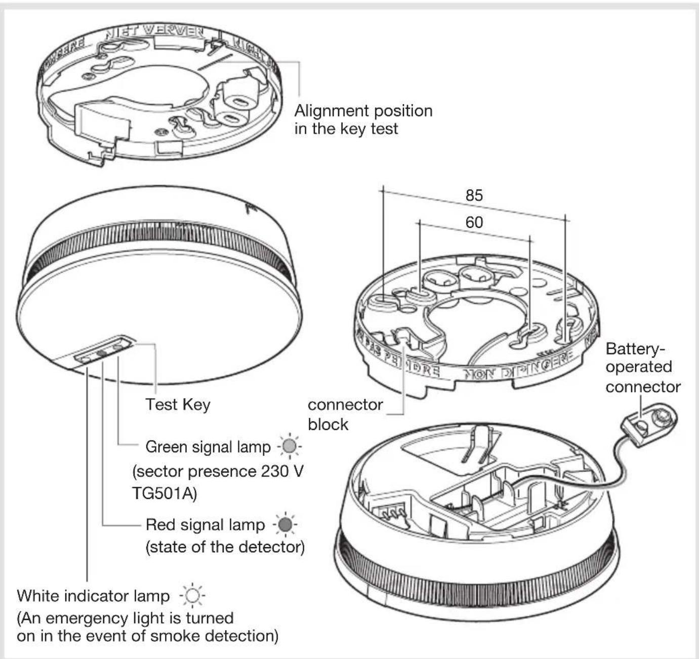
Description
Alimentation
TG 500A / TG 500B
Connect the battery, making sure that the battery connections are correct. The red indicator lamp flickers for 15 sec, then once every 10 sec, signalling the normal operation of the detector.
TG 501A
Connect the battery, making sure that the direction of battery connections are correct and connect the product to the sector 230 V on terminals L/N. The red indicator lamp flickers for 15 sec, then once every 10 sec, signalling the normal operation of the detector. The green indicator indicates the sector presence.
Installation of the detector
Selection of the installation location
The detector shall be installed:
- In rooms subject to a risk of fire (living rooms with a fireplace, childrens rooms, occupied attics or basements...),
- Preferably at the center of the ceiling,
- Away from air outlets likely to disperse smoke,
- At a distance greater than 50 cm from any obstacle (wall, partition, beam...),
- At each end of a corridor of a length greater than 10 m.
If the installation at a horizontal ceiling is not feasible, install it: - At a distance greater than 50 cm from the ceiling and from any room angle
- Away from any electric disturbances (electric meter, metal box, electronic ballast...),
- In the event of fixing to a metal wall: insert a nonmagnetic material support wedge (wood or plastic) between the base and the wall.
The detector shall not be fixed:
- Directly on a metal surface,
- near (minimum distance 50 cm) an electronic ballast, low voltage transformer, energy saving bulbs, etc.,
• In very dusty rooms, - In a room where the inside temperature can fall below -10ircC or above +50ircC , resulting in a failure of the detector,
- At a distance less than 1m from any heating, cooling or ventilation outlet, by which smoke could be dispersed,
- At a distance less than 6 m from any fireplace or wood stove where flue gas is likely to release unwanted alarm,
- In a room where cooking and steam fumes are likely to cause an unwanted false alarm,
- In a room where there is a risk of condensation or moisture (such as bathrooms, wash-houses...),
- At the top of an ogival ceiling (with an A shape), where an air pocket can be formed and prevent smoke from reaching the detector.
Fixing
Fixing with flush-mounting box
For boxes of 60 mm diameter: use holes marked 60
For boxes of 85 mm diameter: use holes marked 85.
Fix the base using suitable screws.
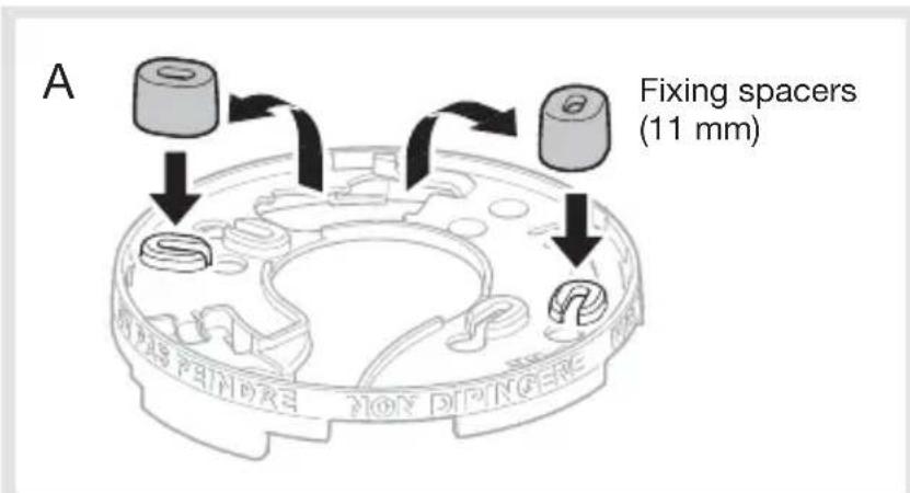
Projecting mounting (Fig A)
- Place the base in the desired location, then mark the position of the 2 fixing holes using a pencil (ref. mark 60 or 85).
- Drill holes using a 5 mm ∅ drill bit.
- Fix the base using suitable fixings.
For interconnecting cabling, remove the 2 fixing spacers and insert them between the ceiling and the mounting base by capping the 2 selected fixing holes.
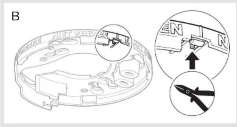
Optional locking of the detector on the mounting base (Fig B).
Optional locking is designed to prevent unauthorized removal of the detector.
Using cutting pliers, cut the locking nipple.
Opening will now be possible only by means of a flat blade screwdriver.
Align the 2 locating arrows marked on the mounting base and the detectors, then lock the unit by turning clockwise.
The detector cannot be locked on its base if the battery is not inserted in its housing.
Do not use force to lock the unit.
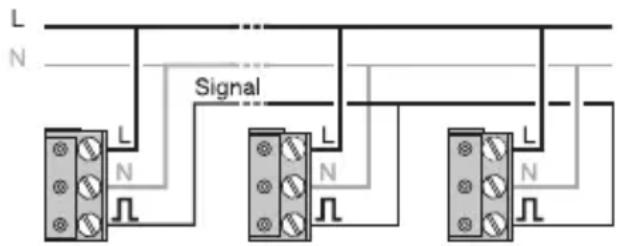
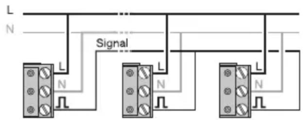
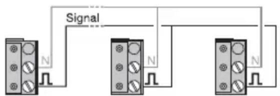
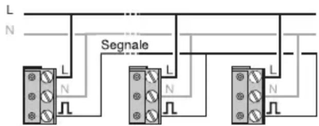
Installing several detectors in a network
It is possible to inter-connect up to 40 detectors to make alarm activation possible over the whole range of smoke detectors of the home.
- After the detector's mounting base has been installed, unfasten the connector block.
- Then do the wiring as follows:
TG 500A / TG 500B
TG 501A
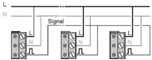
For a cable of 1.5 mm csa, the distance shall not exceed 400 m.
- Fasten the connector block back onto the supporting base.
- Lock the detector on its base.
Connect only detectors of the same model within the network.
To install TG501 detectors in a network, an asymmetric power supply can be used. A separate cutout should be used for protection in this case.
For energy supply and signal forwarding of the smoke detectors a cable (NYM-0/3 x 1.5 mm 2 or NYM-4 x 1.5 mm 2 with earth wire) has to be laid separately.
Testing the detector
Although the alarm level is reduced during a manual test of a smoke detector, it is advisable to inform neighbours prior to running the test and to use all suitable hearing protective devices.
Never use a naked flame for testing the smoke detector.
Manual test
Press (for approximately 5 sec) the test key until the built-in alarm is released.
The alarm sounds until the test button is released:
| Detector at the source of the smoke detection signal | Other wired inter-connected detectors |
| The unit flashes quickly | The unit flashes quickly |
| The unit flickers every sec. | An emergency light is turned on 1 sec. |
| The alarms sounds for 1 sec (73 dB (A) from a 3 m distance), then stops for 1 sec. | The alarms sounds for 1 sec (73 dB (A) from a 3 m distance), then stops for 2 sec. |
| The unit flashes quickly | The unit flashes quickly | |
| The unit flickers every sec. | An emergency light is turned on 1 sec. | |
| The alarms sounds for 1 sec (73 dB (A) from a 3 m distance), then stops for 1 sec. | The alarms sounds for 1 sec (73 dB (A) from a 3 m distance), then stops for 2 sec. |
Detection test:
Using the smoke generator, spray smoke through the slots about 10 cm away from the detection head for 1 to 2 seconds.
When a manual test has been performed less than 5 minutes before using the smoke generator, the detector issues a series of audible signals within the next 10 seconds. These are closer and closer together until the detector is triggered (12 to 22 seconds after spraying). If the detector does not beep, there is not enough smoke around the detection head. Spray some more smoke through the slots.
The manuel test is to be carried out at least once a month, in particular after a long absence.
Manual disabling of the detector
It is possible to disable the detector for a 15 min. period:
- Prior to activities likely to produce dust (sweeping of a dusty room, of a chimney...) and cause unwanted alarm activation,
- To stop alarm in the event of detection of non-dangerous smoke.
In order to disable the detector, press the test key until the 1st beep sounds or until the detector stops its built-in audible alarm. The indicator signalling the state of the detector flickers every 2 sec.
After the 15 min. disable period has passed or after a manual test, the detector is set back automatically into normal operation with the detector state indicator flickering every 10 s.
For the 15 min. disable period, the detector will not detect any smoke, nor emit any audible alarm.
In the case of an installation in network and of a non-dangerous smoke detection, it is obligatory to inhibit the detector at the origin of detection (led red twinkling) to stop the ringing.
Indication of faults
Power supply fault:
Detector at the source of the fault indication
 | TG 500A/TG 500Bthe unit flickers once every 5 sec. | TG 501A- |
 | the unit emits 2 fast beeps every 60 sec | |
After the power supply fault has occurred, the detector will operate normally for a 30-day period. However is advisable to replace the battery as soon as possible.
If the sound indication of the power supply failure occurs at an inappropriate time, it is possible to postpone its occurrence for an 8-hour delay over a maximum 7-day period by pressing the test key until the 1st beep is emitted.
This is the time period available for replacing the battery.
Indication of detection head clogging:
Detector at the source of the fault indication
 | TG 500A/TG 500Bthe unit flickers 8 times over an 8-sec period | TG 501A- |
 | the unit beeps fast 8 times over a 58-sec period | |
If the sound indication of the clogged detection head state is activated at an inappropriate time, it is
possible to postpone its occurrence for an 8-hour delay over a maximum 7-day period by pressing the test key until the 1st beep is emitted.
This is the time period available for cleaning the detector.

Maintenance
Detection head maintenance
The regular maintenance of the detector is of upmost importance. The detection head slots shall be vacuum-cleaned at least once a year or upon each indication of detection head clogging (See section on Fault indication).
If the detection head clogged indication remains after de-dusting, replace the detector.
Smoke detectors shall in any case be replaced after 10-year operation.
The smoke detector contains no radioactive material.
Please comply with local regulations for the disposal of unusabledetectors.
Battery replacement
A. If the optional opening of the detector is not locked (See section on Fixing):
- Take the detector off its mounting base by turning it counter clockwise until the unlock click is heard.
- Replace the worn battery.
- Lock the detector back onto its base.
- Carry out a test (See section on Test of detector).
B. If the optional opening of the detector is locked (see Fixing):
- Insert a flat blade screwdriver into this notch.
- Take the detector off its mounting base by turning it counter clockwise until the unlock click is heard.
- Replace the worn battery.
- Lock the detector back onto its base.
- Carry out a test (See section on Test of detector).
It is mandatory to replace the battery initially supplied with an alkaline battery of the same type (9 V, 6LR61).

Dispose of worn batteries according to local waste disposal regulations.
In case of any works in the room
Painting the detector is prohibited.
Protect the detector by covering it fully with the plastic cover supplied, prior to carrying out any work in the room after detector's installation.
The operation of the smoke detector is not possible in partnership with a sprinkler device.
Warranty
A warranty period of 24 months is offered on hager products, from date of manufacture, relating to any material or manufacturing defect. If any product is found to be defective it must be returned via the installer and supplier (wholesaler). The warranty is withdrawn if:
- after inspection by hager quality control dept the device is found to have been installed in a manner which is contrary to IEE wiring regulations and accepted practice within the industry at the time of installation.
- the procedure for the return of goods has not been followed. Explanation of defect must be included when returning goods.
Getting ready for fire emergency
• Prepare an evacuation route.
- Draw up an emergency plan for all rooms.
- In case of fire, exit the room by crawling on the floor as there is less smoke at that level.
- Wake up everybody as soon as the alarm is activated.
- Set a meeting point outside the home in advance.
- Close all windows and doors.
- Call the fire department.
Summary of reactions and signals of the detector
Normal operation
| All your détectors | |
 | 1 flash every 10 sec. |
Smoke detection (1)
| Detector at the source of the smoke detection signal | Other wired inter-connected detectors | |
 | The unit flashes quickly | - |
 | An emergency light is turned on | An emergency light is turned on |
 | A built-in alarm is released on a continuous basis (85 dB(A) from 3 m) | A modulated built-in audible alarm is released (85 dB(A) from 3 m) |
(1) Alarm sounds until smoke is dissipated
Test of the detector (2)
| Detector at the source of the smoke detection signal | Other wired inter-connected detectors | |
 | The unit flashes quickly | The unit flashes quickly |
 | The unit flickers every sec. | An emergency light is turned on 1 sec. |
 | The alarms rings for 1 sec (73 dB (A) from a 3 m distance), then stops for 1 sec. | The alarms rings for 1 sec (73 dB (A) from a 3 m distance), then stops for 2 sec. |
(2) Alarm sounds when the key test is pressed for more than 5 sec. and until this key is released
of the detector
It is possible to disable the detector for a 15 min. period:
- Prior to activities likely to produce smoke (sweeping of a dusty room, of a chimney...) and cause unwanted alarm release,
- o stop alarm in the event of detection of non-dangerous smoke.
In order to disable the detector, press the test key until the 1st beep sounds or until the detector stop its built-in audible alarm.
The indicator signalling the state of the detector flickers every 2 sec.
For the 15 min. disable period, the detector will not detect any smoke, nor release any audible alarm.
After the 15 min. disable period has passed or after a manual test, the detector is set back automatically into normal operation with the detector state indicator flickering every 10 s.
Indication of faultsManual disabling
Power supply fault
Detector at the source of the fault indication
 | TG 500A/TG 500Bthe unit flickers once every 5 sec. | TG 501A- |
 | the unit releases 2 fast beeps every 60 sec. | |
Indication of detection head clogging
Detector at the source of the fault indication
 | TG 500A/TG 500Bthe unit flickers 8 times over an 8-sec period | TG 501A- |
 | the unit flickers 8 times over an 8-sec period | |
Thanks to a twilight cell, the sound indication of power and detection head clogging faults is inhibited during the night and delayed for a maximum 12-hour period.
If the sound indication of the clogged detection head state is activated at an inappropriate time, it is possible to postpone its occurrence for an 8-hour delay over a maximum 7-day period by pressing the test key until the 1st beep is emitted. This is the time period available for cleaning the detector.
Technical characteristics
- Type of detection: optical smoke detector
• Average coverage: 50 m² - Use: interior
- Power supply:
- TG 500A / TG 500B:
- 9 V alkaline battery (Type: DURACELL PLUS / 6LR61) ; battery life approximately 4 years
- 9 V lithium battery (Type: ULTRALIFE/U9VL-J-P); battery life approximately 10 years
- TG 501A:
- 230 V \~
- 9 V alkaline battery (Type: DURACELL PLUS / 6LR61) ; battery life approximately 10 years
- Signalling:
- state of the detector,
- alarm activations,
- faults: red indicator
- Emergency light turn-on in the event of detection: white indicator
• Built-in audible alarm in the event of detection: 85 dB from 3 m
• Built-in audible alarm
- in the event of test,
- for signalling,
-
of a fault: 73 dB from 3 m
-
Wired interconnection: of up to 40 detectors
• Maximum cable length: 400 m max.
• Maximum cable diameter: 1,5 mm 4 - Operating temperature: - 10 °C to + 55 °C
• Storage temperature: - 10 °C to + 60 °C
• Protection class: IP32 - Dimensions (D x H): 125 mm x 48 mm
- Weight: 210 g
• Standards: 14604: 2005
Non-binding document, subject to modification without notice.
The smoke detector TG500A/B is in conformity with the requirements of the regulation (EU) N° 305/2011 and with all essential characteristics of the harmonized standard EN 14604 (2005). The declaration of performance of the product TG500A/B can be downloaded on hager commercial internet site of the concerned country.
The smoke detector TG501A is in conformity with the requirements of the regulation (EU) N° 305/2011 and with all essential characteristics of the harmonized standard EN 14604 (2005). The declaration of performance of the product TG501A can be downloaded on hager commercial internet site of the concerned country.
Inhoudsopgave
Introductie.... 38
TG 501A
F-67212 OBERNAI CEDEX
Tél. +333 88 49 50 50


- TG 500A (white)
- TG 500B (silver)
- TG 501A (white)
- Presentation
- Operation principle
- Description
- Alimentation
- TG 500A / TG 500B
- TG 501A
- Installation of the detector
- Selection of the installation location
- The detector shall be installed:
- The detector shall not be fixed:
- Fixing
- Fixing with flush-mounting box
- Projecting mounting (Fig A)
- Optional locking of the detector on the mounting base (Fig B).
- Installing several detectors in a network
- Testing the detector
- Manual test
- Detection test:
- Manual disabling of the detector
- Indication of faults
- Power supply fault:
- Indication of detection head clogging:
- Maintenance
- Detection head maintenance
- Battery replacement
- In case of any works in the room
- Painting the detector is prohibited.
- Warranty
- Getting ready for fire emergency
- Summary of reactions and signals of the detector
- of the detector
- Indication of faultsManual disabling
- Power supply fault
- Indication of detection head clogging
- Technical characteristics
- Inhoudsopgave
Brand : HAGER
Model : TG500AL
Category : Smoke detector