Eco Plano II - Fan CasaFan - Free user manual and instructions
Find the device manual for free Eco Plano II CasaFan in PDF.

User questions about Eco Plano II CasaFan
0 question about this device. Answer the ones you know or ask your own.
Ask a new question about this device
Download the instructions for your Fan in PDF format for free! Find your manual Eco Plano II - CasaFan and take your electronic device back in hand. On this page are published all the documents necessary for the use of your device. Eco Plano II by CasaFan.
USER MANUAL Eco Plano II CasaFan
natural_image
Line drawing of a four-bladed propeller fan with no text or symbols
text_image
3 9 RS OFF LIGHT VCE
UK CA
DECKENVENTILATOR
CEILING FAN
VENTILATEUR DE PLAFOND
VENTILATORE DA SOFFITTO
VENTILADOR DE TECHO
STROPNÍ VENTILÁTOR
PLAFONDVENTILATOR
WENTYLATOR SUFITOWY
Radio frequency: 433,92 MHz
Maximum transmitting power: <10dBm
Eco Plano II
natural_image
Simple line drawing of a person sitting on a bench using a book (no text or symbols)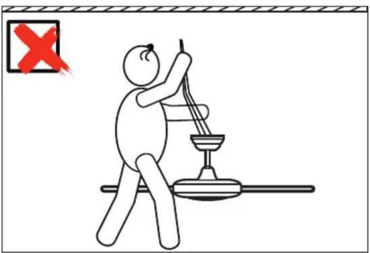
text_image
Safety warning illustration showing a person using a tool to lift a device, with a red 'X' symbol indicating failure.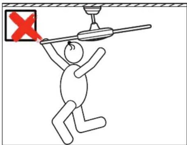
text_image
Safety warning illustration showing a person using a power bulb to lift a wall, with a red 'X' symbol indicating failure.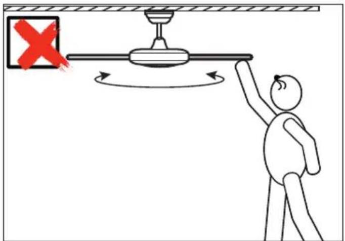
text_image
Diagram showing a person using a pulley system with a red X mark indicating failure, and directional arrows indicating rotation.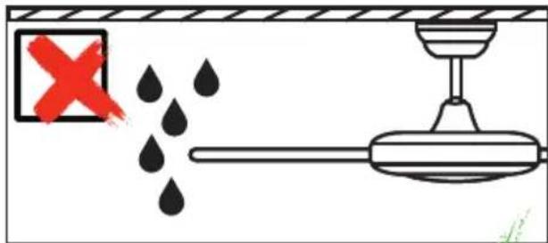
text_image
Safety warning diagram showing a water drop labeled 'X' and a valve with liquid, indicating incorrect safety.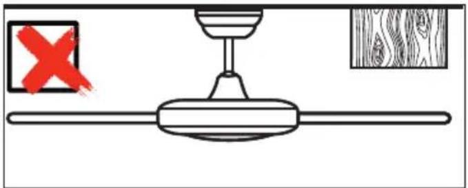
natural_image
Diagram of a ceiling fan with a handle and wooden panel, showing a red X mark and a blue square (no text or symbols)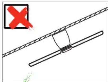
text_image
Diagram showing a cable with a weight and a red X symbol, likely indicating failure or invalid status.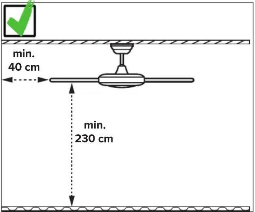
Safety instructions 7–9
Parts 28–29
Installation ceiling bracket 32-34
Electrical connections ......36
Assembling....32–44
Initial operation 44-48
Coding remote control....47
Operation....48–51
Troubleshooting....53
Cleaning/Maintenance 53
Hints and Tips....60
Disposal....64
IT
INDICE
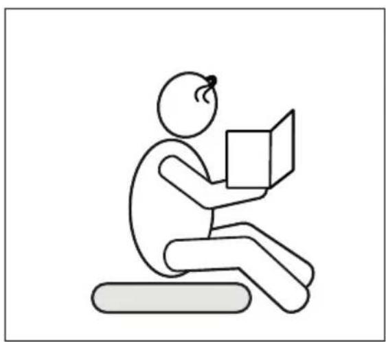
About this operating manual
Before using the CasaFan fan, read the mounting and operating manual carefully. For the safety of persons it is important to follow these instructions!
| Explanation of symbols: | |
| WARNING: Electric voltage! | ATTENTION: |
| Warns you of immediate danger to life. Indicates risks to health and possible damage to property. | |
| With electrical devices, there is a danger to life from electric shock if used improperly, installed incorrectly or if the safety instructions are not observed! | |
SAFETY ADVICES
- Keep the operating manual within reach. Never pass the fan onto another person without the operating manual.
- This ceiling fan is for circulating dry room air. Their use in machines, outside, in garages, in moist or wet rooms or rooms in danger of fire or explosion, is not permitted.
- This appliance can be used by children aged from 8 years and above and persons with reduced physical, sensory or mental capabilities or lack of experience and knowledge if they have been given supervision or instruction concerning use of the appliance in a safe way and understands the hazards involved.
- Cleaning and user maintenance shall not be made by children without supervision.
- If unusual oscillating movement is observed, immediately stop using the ceiling fan and contact the manufacturer, its service agent or suitably qualified persons.
- Replacement of parts of the safety suspension system device shall be performed by the manufacturer, its service agent or suitably qualified persons.
- Mounting of the suspension system shall be performed by the manufacturer, its service agent or suitably qualified persons.
GB
- Before accessing the connection and installation, the current must be disconnected on all poles (fuse in fuse box).
- Children shall not play with the appliance.
- Ensure that the fan is switched off from the supply mains before service and maintenance.
- The electrical connection and electrical maintenance of this fan may only be carried out by a trained electrician, a skilled electrician or an appropriately qualified person.
- The voltage details on the rating label are to conform with the available mains voltage.
- Do not run the cables over sharp edges and under no circumstances squeeze the cables during installation.
- Only operate the ceiling fan when completely assembled!
- WARNING! The mains connection requires a two-pole isolating switch with a contact opening width of at least 3 mm. The disconnecting device must be integrated into the fixed wiring according to the valid technical regulations.
- The electrical safety of the fan is only guaranteed if the earthing system of the building installation is installed in accordance with the regulations and the fan is connected to it.
- The mains connection to which the fan is connected must comply with the applicable local standards.
- Choose a safe place for installation and make sure that there are no objects within the area of rotation.
- The construction and fixture of the holder and ceiling is to be able to bear 4 times the weight of the fan when being moved.
- None of the fan blades are to be less than 2.3 m from the ground.
- Keep the fan away from heat sources. The minimum distance to radiant heaters and stoves is 1.5 m.
- Before first using after the setup, all electrical and mechanical connections are to be checked in order to prevent any fall, fire or electric shock.
Observe notes on disposal!
Our ceiling fans are quality products and designed for a long service life.
- Do not dispose of a appliance at the end of its service life and any batteries required to operate the appliance in household waste!
- Find out about local return and recycling possibilities and use the existing collection points in your area for disposal.
- Dispose of packaging material that is no longer required in an environmentally friendly manner and inaccessible to children.
- There is a risk of suffocation for children by inhaling or swallowing parts of the packaging.
PARTS (Figure A, page 28)
Unpack the fan and compare the package contents for completeness. All the parts shown in the figure are to be present and undamaged.
| Technical data: | ||
| Type Eco Plano II 112 Eco Plano II 132 | ||
| Mains voltage 100 - 240 V | ~ | |
| Frequency 50/60 Hz | ||
| Power motor 14,4 W (max.) 26.5 W (max.) | ||
| Protection class I/IP20 | ||
| No. of speeds 6 (with remote control) | ||
| Dimensions ∅ × H (mm) approx. 1120 × 200 approx. 1320 × 200 | ||
| Distance ceiling – blades approx. 200 mm | ||
| Weight approx. 5,5 kg approx. 6,0 kg | ||
| Optional light kit | EP-LED #2763, #2761, #2764, #2765, #2762 | |
| Service interval | once a year | |
| Subject to technical modifications. | ||
text_image
Technical diagram of an electrical lamp with numbered components and wiring labels10

text_image
3 4 10 12 14 1611
12
13
natural_image
Simple line drawing of a rounded rectangular shape with a circular base, labeled with number 6 (no text or symbols on the shape itself)
natural_image
Simple line drawing of an elongated biological structure with two labeled parts (8 and 9), no text or symbols present.7
natural_image
Simple line drawing of a circular bowl or basin (no text or symbols)DE EINZELTEILE
① Hanger Bracket
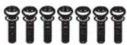
② Motor retaining screws (4×)
3 Terminal Block
4 Motor Assembly
⑤ Fan Wire
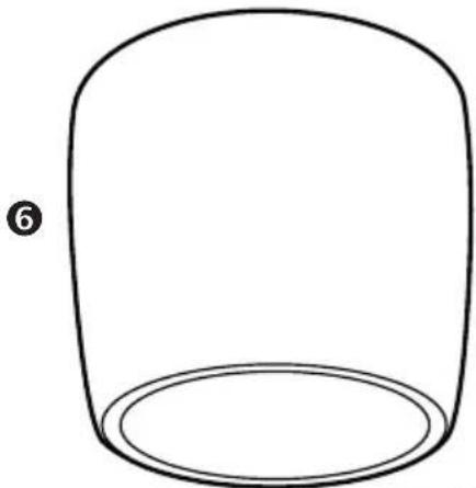
6 Motor housing
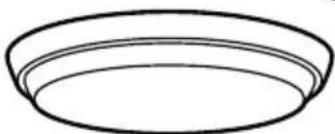
7 Lower Cover
8 Blade (4×)
9 Blade Support (4×)
10 Remote Control
⑪ Blade screw (8×)
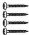
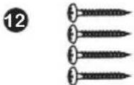
12 Bracket Screw for wood (4×)
13 Balancing kit
14 Safety rope
FR PIÈCE DÉTACHÉE
text_image
Technical diagram of an electrical lamp structure with numbered components and wiring labels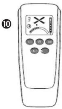
text_image
10 3 X 0 0 0 100 0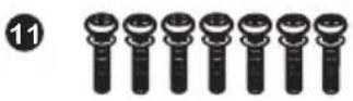

text_image
Diagram showing a cooking pan with labeled parts including lid, pan, and lid with numbered labels 6, 7, 8, and 9.ES COMPONENTES
natural_image
Diagram of a ceiling lamp with colored wires and connectors, showing a small knob below (no text or symbols)min. 24 kg !
DE
WARNING: Danger of electric shock! Before commencing installation, turn off electricity supply at the main power box or disconnect power by removing fuse.
ATTENTION: Follow all installation directions. Improper installation can lead to injuries and material damage.
- The place of installation (ceiling) must have a load capacity of at least 24 kg. - Use only for your type of ceiling suitable screws and plugs (not supplied).
FR
text_image
Diagram showing cable installation process with labeled components and wiring connections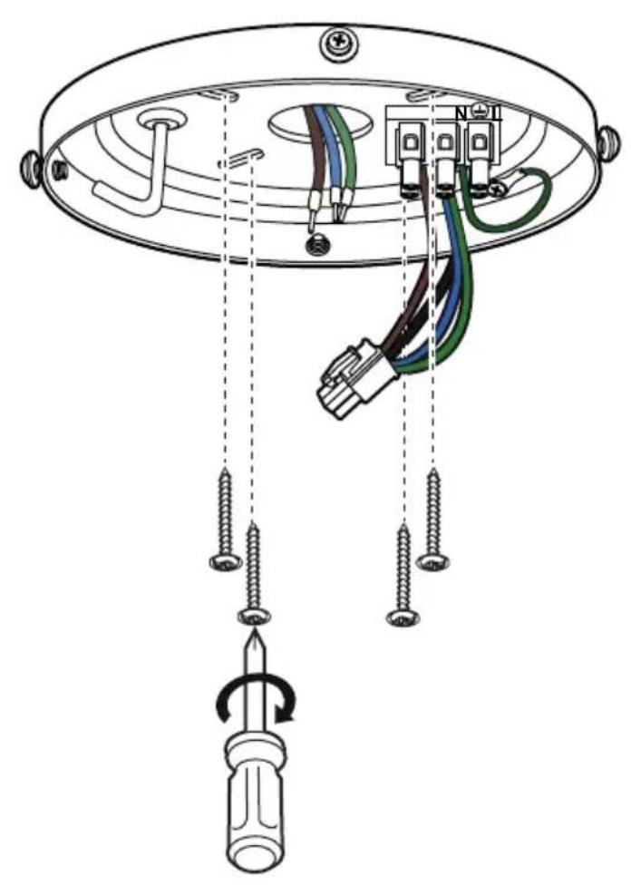
text_image
Diagram of a ceiling lamp installation showing screwdriver, cable, and connector components with wiring and mounting pointsDE Befestigen Sie den Deckenhalter mit 2 oder 4 Schrauben an der Decke. Verwenden Sie nur die für Ihre Deckenart geeigneten Schrauben und Dübel (nicht im Lieferumfang).
GB Securely attach the hanger bracket to the ceiling joist using the lag bolts supplied. Use only for your type of ceiling suitable screws and bolts (not supplied).
FR Fixer le support de suspension en utilisant les vis plates adaptées à votre plafond (vis non fournies)
IT Fissare la staffa a soffitto al soffitto con 2 o 4 viti. Utilizzare solo viti e tasselli adatti al tipo di soffitto (non inclusi).
ES Fijar el soporte del techo al techo con 2 o 4 tornillos. Utilice sólo los tornillos y tacos adecuados para su tipo de techo (no incluidos).
CZ Připevněte stropní držák ke stropu pomocí 2 nebo 4 šroubů. Používejte pouze šrouby a hmoždinky, které jsou vhodné pro váš typ stropu (nejsou součástí dodávky).
NL Bevestig de plafondbeugel aan het plafond met 2 of 4 schroeven. Gebruik alleen voor uw type plafond geschikte schroeven en bouten (niet bij de levering inbegrepen).
PL Przymocuj wspornik sufitowy do sufitu za pomocą 2 lub 4 śrub. Stosować wyłącznie śruby i kołki odpowiednie do danego typu sufitu (nie zawarte w dostawie).
text_image
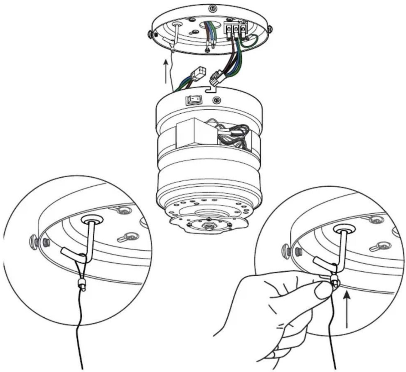
Technical diagram showing installation of a lamp with wiring and components, including close-up views of internal wiring and hand tool application.GB Guide the safety rope over the hook on the ceiling bracket and tighten it firmly.
natural_image
Diagram of a cable connector with colored wires and a black arrow pointing to a terminal block (no text or symbols present)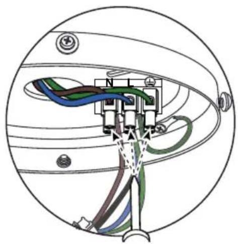
natural_image
Diagram of a cable connector with colored wires and connectors, enclosed in a spherical housing (no text or labels)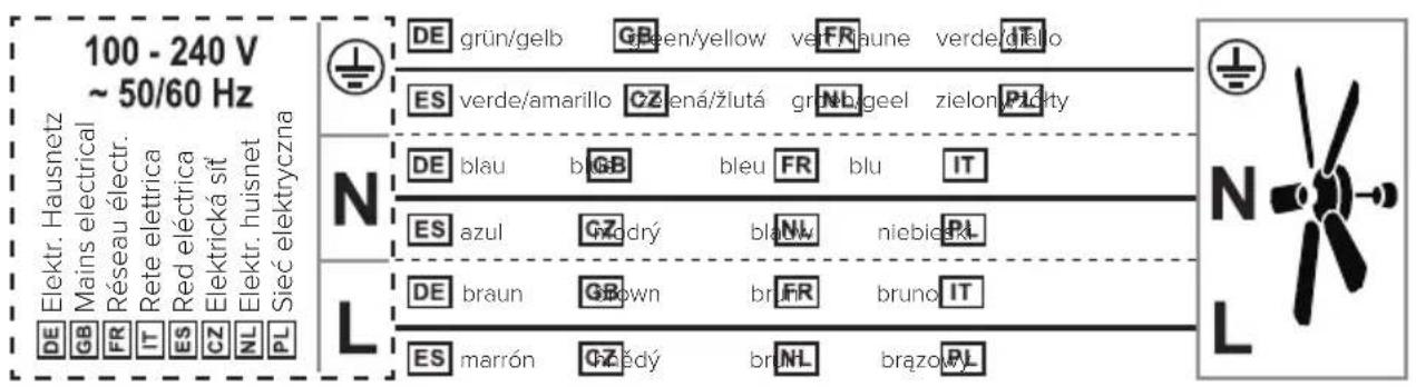
text_image
100 - 240 V ~ 50/60 Hz Elektr. Hausnetz Mains electrical Réseau électr. Rete elettrica Red eléctrica Elektrická sit Elektr. husnet Sieć elektryczna DE GB FR IT ES CZ NL PL DE grün/gelb Green/yellow ve FR baune verde/gralo ES verde/amarillo CZ ená/žlutá grn NL geel zielon PL octy N DE blau bleu FR blu IT ES azul CZ drý blauv niebie RL L DE braun Brwn br FR bruno IT ES marrón CZ šdy br NL brązow PLDE Schließen Sie die Kabel mit der Netzspannung an die Lüsterklemme an.
GB Connect the cables with the mains voltage to the terminal block.
FR Connectez les câbles avec la tension du secteur à la bornier de raccordement.
IT Collegare i cavi con la tensione di rete alla blocchetto terminali.
ES Conecte los cables con tensión de red al bloque de terminales.
CZ Připojte kabely se síťovým napětím ke svorkovnici.
NL Sluit de kabels met de netspanning aan op de aansluitblok.
PL Podłączyć przewody z napięciem sieciowym do blok zacisków.
natural_image
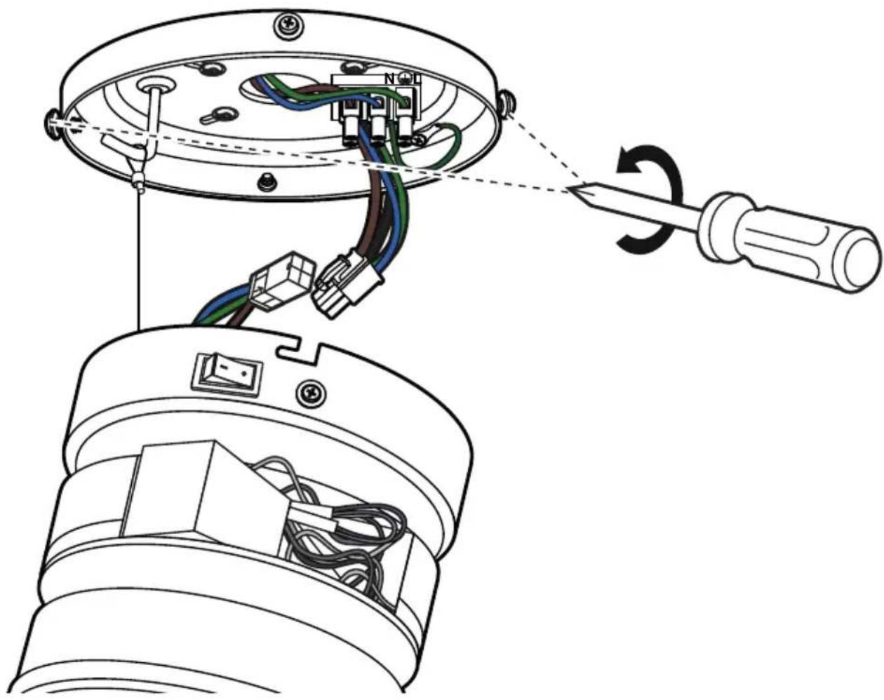
Technical diagram showing wiring connections between a ceiling lamp and a base device, with no visible text or symbols.GB Remove 2 opposing screws from the ceiling bracket and loosen the other 2 screws by about 2 turns.
natural_image
Technical diagram of an electrical connector assembly showing internal wiring and mounting points (no text or symbols)text_image
Technical diagram illustrating the assembly and disassembly of a mechanical component, showing exploded view and wire repair steps.natural_image
Cross-sectional diagram of a mechanical device showing internal components and directional arrows (no text or symbols)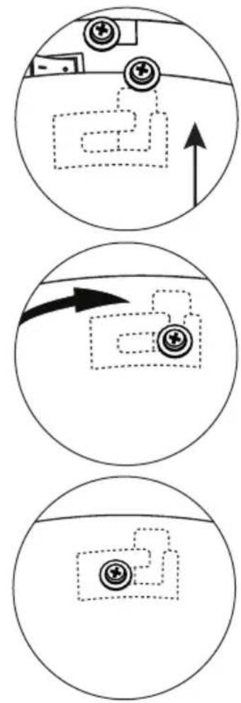
flowchart
graph TD
    A["Device placement"] --> B["Navigation"]
    B --> C["System interaction"]
    C --> D["Final system"]
DE Setzen Sie die Gehäuseabdeckung auf die Motoreinheit und führen Sie die Bajonetthalterung in die 3 Bolzen an der Deckenhalterung. Drehen sie die Gehäuseabdeckung nach rechts, um es in den Bolzen zu sichern. Das Gehäuse muss nun fest an der Deckenhalterung sitzen.
Place the housing cover on the motor unit and insert the bayonet mount into the 3 bolts on the ceiling mount. Turn the housing cover to the right to secure it in the bolts. The housing must now sit firmly on the ceiling bracket.
FR Placer le couvercle du boîtier sur l'unité moteur et insérer la fixation à baïonnette dans les 3 boulons de la fixation au plafond. Tourner le couvercle du boîtier vers la droite pour le fixer dans les boulons. Le boîtier doit maintenant reposer fermement sur le support de plafond.
IT Posizionare il coperchio dell'alloggiamento sull'unità motore e inserire il supporto a baionetta nei 3 bulloni del supporto a soffitto. Ruotare il coperchio della custodia verso destra per fissarlo nei bulloni. L'alloggiamento deve ora essere posizionato saldamente sul supporto a soffitto.
ES Coloca la unidad del motor con la montura de bayoneta en los dos tornillos y gira la unidad del motor a la derecha. Ahora reemplace los dos tornillos previamente quitados y apriete los 4 tornillos. Asegúrate de que el interruptor esté encendido.
Vložte motorovou jednotku s bajonetovým držákem do dvou šroubů a otočte motorovou jednotku doprava. Nyní vložte dva šrouby, které jste odstranili, zpět a utáhněte všechny 4 šrouby. Zkontrolujte, zda je přepínač zapnutý.
natural_image
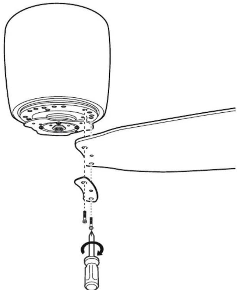
Technical line drawing of a mechanical assembly with a tool inserted into a component (no text or symbols)GB Attach 2, 3 or 4 blades to the motor with blades screws and lade supports as required.
text_image
Technical diagram showing mechanical assembly with labeled components and directional arrows indicating motion or movement.DE Schrauben Sie, je nach Wunsch, 2, 3 oder 4 Flügel mit je 2 Schrauben an den Bohrungen mit den Markierungen 3/4.
GB Screw 2, 3 or 4 blades with 2 screws each to the holes with the markings 3/4, according to your wishes.
FR Vissez, au choix, 2, 3 ou 4 pales avec 2 vis chacune dans les trous marqués 3/4.
IT Avvitare 2, 3 o 4 pales con 2 viti ciascuna ai fori con le marcature 3/4, secondo i vostri desideri.
ES Atornille, como desee, 2, 3 o 4 aspas con 2 tornillos cada una a los agujeros marcados con 3/4.
CZ Podle svých požadavků zašroubujte 2, 3 nebo 4 křídla se 2 šrouby do otvorů označených 3/4.
NL Schroef 2, 3 of 4 bladen met telkens 2 schroeven in de gaten met de markering 3/4, naargelang uw wensen.
PL Przykręcić 2, 3 lub 4 arkusze po 2 wkręty w otwory oznaczone 3/4, w zależności od potrzeb.
natural_image
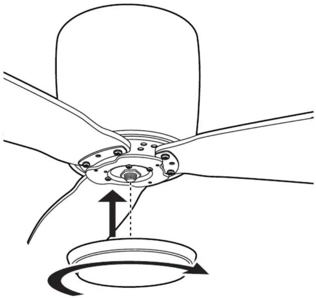
Technical diagram of a mechanical assembly with no visible text or symbolsGB Turn the lower cover onto the motor shaft. CAUTION: do not too tighten, otherwise the cover will be damaged!
natural_image
Line drawing of a three-bladed propeller or fan with no text or symbolsDE Ihr Ventilator ist jetzt bereit zum erstmaligen Betrieb.
GB Your fan is now ready to run for the first time.
FR Votre ventilateur est maintenant prêt pour la mise en service.
IT Il tuo ventilatore è ora pronto per il funzionamento iniziale.
ES Su ventilador está listo para la operación inicial.
CZ Váš ventilátor je nyní připraven k provozu poprvé
NL Uw ventilator is nu klaar voor het eerste gebruik.
PL Wentylator jest teraz gotowy do pierwszego uruchomienia.
- Several ceiling fans can be connected to a single hand-held transmitter.
- If several fans within radio range are to be programmed on their own hand-held transmitters, only the fan currently to be programmed must be switched on. The same applies to reprogramming and teaching new blade sizes and numbers.
FR NOTE SUR LA TÉLÉCOMMANDE
GB Insert 1 battery type 6F22 (9V) into the transmitter of the remote control. Do not press any button yet!
text_image
Diagram showing two battery charging setups with labeled components and polarity indicatorsGB Switch on the electricity supply for the ceiling fan (fuse).
GB Within first 60 seconds after power on: Press the "OFF" button until you hear two BEEP tones until confirmed.
GB Teach-in size and number of blades
GB Within the first 120 seconds after switching on the power and inserting the battery: Press the "FAN" button until you hear 3 BEEP tones.
- The motor will now run from maximum speed to standstill. The highest level is indicated in the display of the remote control. - At the end of the teach-in procedure, another 3 BEEP tones will sound for confirmation. Your ceiling fan is now ready for operation.
natural_image
Simple diagram showing a cross-shaped object with an arrow pointing to a curved arc, next to a vertical bar (no text or symbols)GB Operation CZ Obsluha
GB Press the "FAN" button to start the fan on low speed.
natural_image
Simple diagram showing a cross-shaped object with an arrow pointing downward, next to a curved arc and a vertical bar (no text or symbols)GB Pressing the "FAN" button again will switch the fan motor one step faster.
text_image
Diagram showing a cross-shaped symbol with an arrow pointing to a curved arc, alongside a vertical line and a flame symbol.GB Press the "F/R" button to change the direction of rotation.
natural_image
Simple diagram showing a windmill symbol above an arc and a vertical line with a flame symbol (no text or labels)GB While the motor is running, press the button to set the shutdown timer. When the set time has elapsed, the fan switches off.
natural_image
Simple line drawing of a hand holding a circular object (no text or symbols)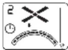
text_image
2 ①GB Each press on this button increases the time of the shutdown timer by one hour.
natural_image
Simple line drawing of a hand holding a circular object (no text or symbols)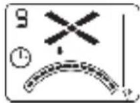
text_image
9 ①GB Press the "OFF" button to turn off the ceiling fan.
NOTE: The luminaire is optional and is not supplied with your ceiling fan.
natural_image
Simple diagram showing a windmill with an upward arrow and a curved arc, next to a vertical scale bar (no text or symbols)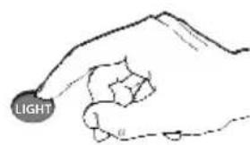
text_image
LIGHT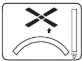
natural_image
Simple diagram showing a windmill symbol above an arc and a vertical line with a flame, no text or labels present.| GB NOTES FOR REMOVING FAULTS | |
| Fault Remedy | |
| The fan does not start | - Check the fuses/trips at the main box and other connections.- Check the fan connection to the mains.- Repeat coding of the fan with the handheld transmitter.- Replace the battery in the handheld transmitter if necessary.- Switch on the main switch on the motor (page 38/39). |
| The fan is noisy | - Check that all bolts and screws have been tightened.- Run in the fan and the bearings for 24 hours. Most noises disappear after this time. |
| The fan vibrates too much | - All screws during assembly of the ventilator, especially those relating to the axis, have an important function. Not tightened screws are the main cause of imbalances.- Please make sure that all screws are tightened. All blades have been weighed and grouped according to weight. If the blade screws of one of the blades are not tightened properly, this could cause massive wobbeling.NOTE: Movement of up to 10 mm is quite acceptable and does not mean a faulty ceiling fan.- Check that the ceiling bracket is firmly anchored to the ceiling. |
| Important:Opening up and repairing the appliance may only be carried out by a qualified electrician! | |
CLEANING/MAINTENANCE

WARNING: Danger of electric shock! Turn off the electricity at the fuse box or circuit breaker before cleaning or servicing your fan.
- Never use water for cleaning your ceiling fan. The appliance must not get wet.
- Do not use petrol or any similar light flammable detergents!
- Clean the surface of the housing and the blades with a dry cleaning cloth.
Regular check
- Check once a year all the screws, especially those of the ceiling suspension, for tightness, retighten if necessary.
- Check electrical connections for proper connection.
Lock protection: The EC/DC motor has a built-in safety feature against blade or motor obstruction during operation. If something obstructs the fan blades or motor, the motor will keep trying to run and then stop operation after about 30 seconds of interruption. Please remove obstacles and reset.
To reset: Turn the fan off by remote transmitter and then turn the fan on.
Over load protection (current limit): The device will limit the maximum current output from the receiver/drive if the fan load has increased abnormally.
Tips
- If your fan is operates automatically after installation and power on, it is because your fan has memorized the previous factory setting. Use the Universal Mode or the learning function and your fan will be ready for use.
- If the fan or light isn't working, reset power (turn the power off for at least 5 seconds and then turn the power back on) and redo the learn function setting.
- It is not possible to remotely operate more than one fan in the same room (in the area where the remote signal can reach to) if they share the same power supply. Separate power supplies (such as using individual wall switches for each fan) is required if you want to separately control more than one fan in same room.
- When the fan is turned on or operated using forward/reverse function, it shutters & goes back & forth until it turns. This is normal and it will take a few seconds to run this operation.
This marking indicates that this product should not be disposed with other household wastes throughout the EU. To return your used device, please use the return and collect system or contact the retailer where the product was purchased. They can take this product for environmental safe recycling. This product conforms to EU Directive 2012/19/EU. This appliance bears the symbol of the barred waste bin. This indicates that, at the end of its useful life, it must not be disposed of as domestic waste, but must be taken to a collection centre for waste electrical and electronic equipment, or returned to a retailer on purchase of a replacement. It is the user's responsibility to dispose of this appliance trough the appropriate channels at the end of its useful life. Failure to do so may incur the penalties established by laws governing waste disposal. Proper differential collection, and the subsequent recycling, processing and environmentally compatible disposal of waste equipment avoids unnecessary damage to the environment and possible related health risks, and also promotes recycling of the materials used in the appliance. For further information on waste collection and disposal, contact your local waste disposal service, or the shop from which you purchased the appliance. Manufacturers and importers fulfil their responsibilities for recycling, processing and environmentally compatible disposal either directly or by participating in collective systems.
FR ATTENTION
natural_image
Two crossed-out trash bins, one with a 'X' symbol and the other with a blank space (no text or labels)EU Declaration of Conformity
Wir, die Firma
We, the company
CasaFan GmbH
Senefelderstr. 8
Hasselroth, 63594, Germany
declare under our sole responsibility that the following product
Geräteart/ type of product:
Deckenventilator / ceiling fan
Handelsmarke/ trademark:
CasaFan
Modell
Artikelnummer
weitere Angaben
model
article-no
further details
Eco Plano II 112
311280, 311282, 311283, 311284, 311285
Eco Plano II 132
313280, 313282, 313283, 313284, 313285
meets the essential requirements of the following EU-Directives:
2014/35/EC
Low Voltage Directive
2014/30/EC
Directive on Electromagnetic Compatibility
2014/53/EC
Radio Equipment Directive (RED)
2011/65/EC
Directive on the restriction of the use of certain hazardous substances in electrical and electronic equipment
2009/125/EC
Ecodesign directive
Authorized person for technical documentation:
Name/ name, Position:
Hasselroth, 12.11.2020
Datum/ Date
CasaFan reserves the right to make any changes to the product without prior notice.